
Workshop 8 notes, Week of October 20, 2008
Surface Editing, Materials and Lighting
1. Surface Editing: cutting hole in extruded bspline.
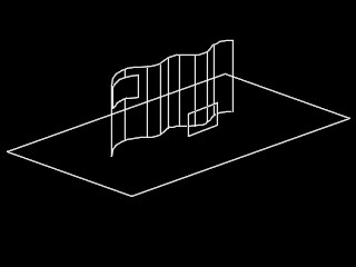
Using the Iso View Window (#2), place a rectangle in the ground plane and then put a bspline inside of the rectangle as depicted in the image below.
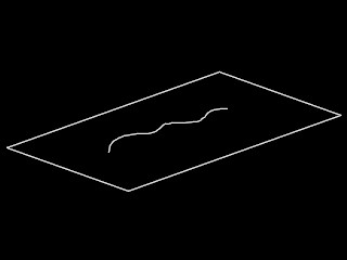
Use the extrude operator to project the curve into a surface.
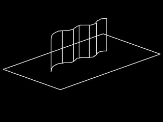
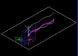
Go into the "F" front construction plane via Accudraw and place a rectangle above the front edge of the ground rectangle and facing the curved wall.
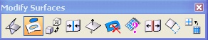
From the Surface Modeling task, select the icon labelled "T" and open the sub-palette titled "Modify Surfaces" as a toolbox.
Select the second icon "Project Trim", and then select the curved wall and the rectangle.

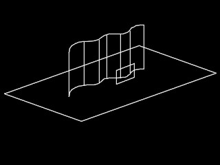
Enter a data point and the retangle will cut a whole in the wall.
2. Surface Editing: using surface to cut wall.
A similar application of surface editing uses a Surface by Section to slice an extruded wall. Here the sequence begins with drawing two bspline surfaces on-top of a simple rectangle in the ground plane.
 |
 |
| Simple rectangle in ground plane |
Bsplines added to ground plane |
Next, the second bspline is moved above the first bspline along the z-axis. A Surface by Section (first icon in Create Surfaces toolbox) is then created from the two bsplines.
 |
 |
|
| Bspline moved above ground plane. |
Select bpslines with Construct Surface by Section tool |
|
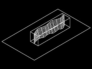
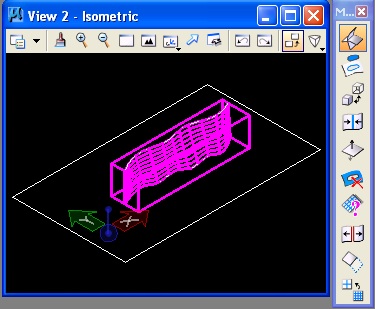
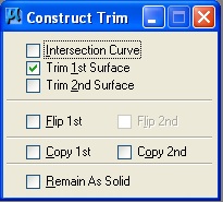
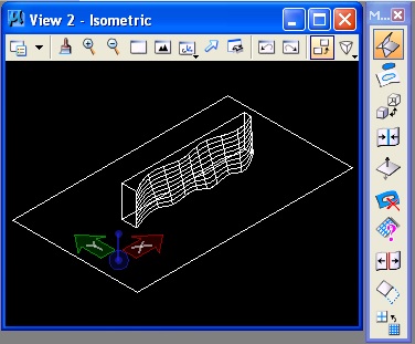
Next, an extruded rectangle is added to the ground plane of the above figure. From the modify surfaces palette (first icon in palette in figure at right below), the Trim Surface tool is applied, where the wall is selected first and the bspline surface is selected second.
 |
 |
| Extruded retangle juxtaposed with sufrace |
Construct Trim Tool with wall selected st and surface 2nd |
 |
 |
| Dialog box settings for Construct Trim Tool |
Result of trim |
3. THREE FILE TYPES ARE USED TO DETERMINE THE ASSIGNMENT OF MATERIALS TO OBECTS IN A MICROSTATION DRAWING.
These files, identified below, are external to the main Microstation DGN file and need to be included separately in any folder where it exists in order to support rendering of materials.
These files are interchangeable between drawings and are stored outside the .dgn file:
3.1 Material Table File (file extension ".mat" such as "myproject.mat") - Determimes the assignment of materials to objects in a cad model by one of two methods: 1) according to layer and color or 2) by direct assignment to individual objects. The Material Table file references Palette files for the description of individual materials.
3.2 Palette File (file extension ".pal") - Describes the definition of materials according to their property values (e.g., transparency). Typically a palette file is created for a group of materials that have similar qualties, such as palette file for marble (e.g., "marble.pal") or a palette file for wood (e.g., "wood.pal").
Materials within a palette file can be defined according to several methods, sometimes in themselves referring to additional image files.
- Definition by properties (e.g. color)
- By procedure (e.g., a specific algorithm for brick or wood)
- By texture mapping (iterally draping an external image file onto a surface)
- By bump mapping (using the greyscale value of an image file to simulate the relief of a material).
- By transparency mapping (iterally draping an external image file onto a surface, with one color selected as transparent)
3.3 Image files, typically jpeg (pseudo 24 bit) or tiff (true 24 bit) are referenced in the definition of individual materials through texture mapping and bump mapping. Occasional such files may also be used in other rendering techniques such as background mapping (an image background to scene, environmental mapping (a six sided box that encloses a model and may be reflected by materials in it), and transparency mapping (an image with a designated transparent color, such as may be used to map figures, such as people or trees, onto a computer model).
4. STANDARD RENDERING
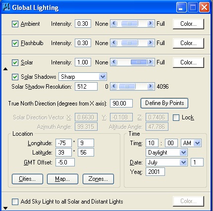
Rendering usually is established with creating one or more light sources. Here, we will setup a rendering with a sunlight set to 10 a.m. by using the Global Lighting dialog box.
- Go to menu item "Settings>Rendering>Global Lighting"
- Set Ambient intensity to 0.3
- Set
"Flashbulb intensity to 0.3
- Set
Solar intensity to 0.3
- Unlock the Solar light by un-checking the lock box
- Use the default time (10 a.m., July 1, 2001)
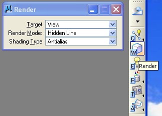
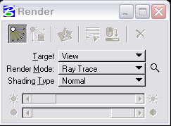
It is possible to render through selecting one of any number of standard algorithms as described in the lecture preceding the workshop. Select the render tool from the "Task List - Visualization" on the right-hand side of Microstation's Application Window:
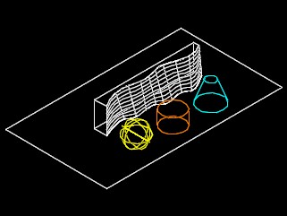
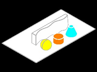
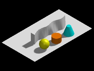
Add three simple solids to the figure from part 2.
Go through the "Render Mode" portion of the render tool to invoke varied rendering algorithms from "Hidden Line" through "Ray Trace".
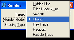
Six different renderings are tested to create the images captured in the table below.
- Hidden Line – shading type: normal
- Filled Hidden Line – shading type: normal
- Smooth – shading type: normal
- Phong – shading type: normal (you may also want to turn off or save shadow maps under Settings>Rendering>General lighting)
- Ray Trace – shading type: normal
- Ray Trace – shading type: anti alias
 |
 |
 |
 |
 |
 |
| Hidden Line |
Filled Hidden Line |
Smooth |
Phong |
Raytrace |
Raytrace - Antialiasing |
5. MATERIAL DEFINITION BY PROPERTIES
For these examples, copy the classes folders examples/ptrace/ptrace & ptrace2 (ies example) to the local hard drive, and, within the folder ptrace, open the file ptrace2.
To initiate material definitions, you need to follow three steps as illustrated below:
- begin by creating a material table file
- initiate or load a material palette file for the definition of individual materials
- define individual materials
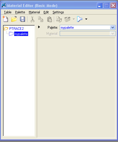
STEP 1: using the task list manager on the upper right hand side of Microstation's application window, select "visualization" and then select the icon labelled "R" (see image below) to open the "Material Editor" dialog box. By default, the prefix name of the material table file ("ptrace2.mat") is the same as the prefix name of the dgn file ("ptrace2.dgn"). This file should be explicitly saved by selecting the menu item "Table" from within the "Material Editor" dialog box and using the "save as" option.
 '
'
STEP 2: under the menu item "palette", select the word "new" to create a new palette file, such as the file "mypalette.pal". This file must also be saved by going to the menue item "Palette" and using the "save as" dialog box when materials are added to it.
STEP 3: Once a palette file has been created, begin to develop the definition of individual materials.
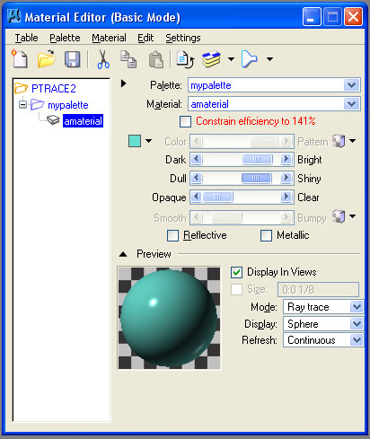
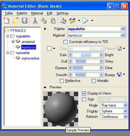
The above material "amaterial" has the following properties set
1. color -base color visible by ambient light (turquoise color as shown)
2. dark/bright - brightness of material under direct illumination
3. dull/siny -shininess or dullness of specular highlight
4. opaque/clear - transmissivity of matarial to light (level of transparency)
Once created, right-clicking on the name of the material. and select the word "assign" opens yet another dialog box by which it may be assigned to an object in the dgn file. Assigning the material by Level/Color is achieve by selecting the first icon in the dialog box and then selecting the object (e.g., the sphere).
As illustrated in the example "Material Editor" dialog box below, note that any dgn file, such as the file named "test.dgn", may reference any number of palette files, such as the files "myproc.pal", "test.pal", and "metals.pal", and that each palette file may contain the definition of any number of materials, such as the materials "grue" and "mybyr" below. A "+" symbol appearing next to the name of the material indicates that it has been assigned to objects in the dgn file by the "Level/Color" method or another method.
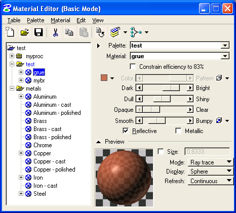
The above material "grue" has the following attributes:
1. color -base color visible by ambient light
2. dark/bright - brightness of material under direct illumination
3. dull/siny -shininess or dullness of specular highlight
4. opaque/clear - transmissivity of matarial to light (level of transparency)
5. smooth/bumpy - bumpiness with respect to bump map (based upon a jpg image not shown)
6. Reflective - reflection of light
7. Metallic - -metallic/mirror like reflection of light
6. TEXTURE MAPPING
Projecting an image as the basis for the definition of a meterial is referred to as "texture mapping".
- Go to class web site for sample materials.
- Class website > handout> material sample website> Greek marble>travertine> skra.
- Save travertine. jpg to folder
- Create a palette file "mymarble" for marble.
- Within the materials table dialog box, use the pulldown menu > palette > new palette (name it marble.pal)
- Right click or click on “new” icon – new material (name it "mytravertine" or an appropriate name)
- Click small checkered box beside color tap to map image to material definition
- Find the file: travertine.jpg
- Right click on travertine and click assign
- Assign it to the rectangle at the center floor of the model by clicking on it
- Render (control the light for a raytrace rendering with the contrast and brightness sliders)

7. TEXTURE MAPPING ADJUSTMENTS
It is possible to change the scale and tile a texture map.
- To tile the image at the proper scale: Select the checkered box for Pattern in side the material editor.
- In the 2nd box, change units from “surface” to “master”. This keys the scale to the master unit (e.g., feet) within the model, rather than have the material expand to whatever size object it is assigned to.
- Adjust units to correct scale (e.g., 4.0 means 4 master units of feet for each direction)
- We can get tiling pattern
if the surface is larger than the unit size specified.
- Render and control the lighting with the slider
- Click on the magnifying glass next to Ray Trace in the Render dialog box
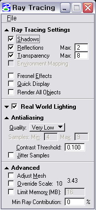
- Adjust antialiasing to “very high,” jitter samples, and adjust mesh (trial and error process)
- this material can be assigned to the rectangle on the ground plane of the model
- you may also adjust advanced tool by selecting the down-arrow tab
- check the class website on raytrace settings for more information on this tool
8. BUMP MAPPING
A bump map assigns a relief map to a surface in a similar dialog to texture mapping. Here the greyscale value of an image is used to simulate the appearance of a surface relief pattern in the object to which it is assigned. The bump map attribute is turned on via the down arrow to the right of the word "bump" in the "Material Editor". Next, a specific image is selected using the selection tool (appears to be two links in a chain) just to the left of the down arrow. A common folder for storring bmp map images is C:\Documents and Settings\All Users\Application Data\BentleyWorkspace\System\Materials\bump. In the figure below, the file "RoughBump.jpg" is selected for the bump map. However, any jpg image can be used for this purpose,

The bump map can be adjusted similarly to an image map, and assigned to the surface of an object as a whole, or assigned on the basis of master units.
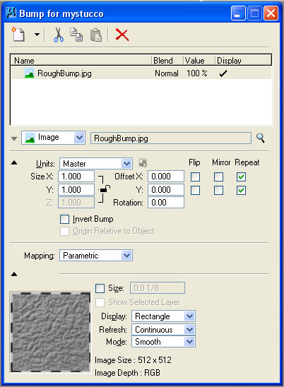
Once the bump map parameters have been established, the material which references it is modified to have a surface relief pattern. The appearance of "myfirstmaterial" is changed accordingnly in the "Material Editor Dialog" box. This material can be assigned to the truncated cone in the dgn file.
9. PRE-DEFINED PALETTE FILES
Apart from the task list manger on the right-hand side of Microstation's application window, you can also open the "Material Editor" dialog box from the top of the view screen by going to "Settings>Rendering>Materials. A number of predefined material palettes are locted on the hard drive of your computer as a part of the typical software installation. For a drawing file with a simple ground rectangle with three objects sitting on top of it (e.g., slab, sphere and cone), you can explore some of the pre-defined palettes as follows.
- Go to Palette>Open and choose C:\Documents and Settings\All Users\Application Data\BentleyWorkspace\System\Materials\pattern
- Open “finishes.pal” and assign “flat warm grey” to an object. (go to “Assign,” then choose the object)
- .The material should then have a “+” next to it and contain the layer and color of the object selected.
- Open palette “glazing.pal” and assign glass to sphere.
- Open palette “metals.pal” and assign brass to cone.
- Open palette “floors.pal” and assign tile semi gloss to rectangle.
- To preserve the new settings, right-click on the table name and save and then on the palettes to save. NOTE: BE CAREFUL. Rather than overwriting pre-defined system palettes, is probably better to save palettes under your own distinct names (e.g., "myglass.pal") and materials within any given palette under distinct names (e.g., myflatwarmgrey) so as to avoid any confusion with system defined materials.
10. BACKGROUND MAP AND DISTANCE CUE(COVERED LAST WORKSHOP)
- Go to Settings>Design File>Views
- Browse for a Background image and check off the box (C:\Documents and Settings\All Users\Application Data\BentleyWorkspace\System\Materials\pattern\SkyBlueSmClouds.jpg)
- Settings>Rendering>View Attributes (or Settings>Rendering>Setup>Render Attributes).
- Change “ Distance cue” to “fog”.
- In the setup menu, it is possible to change near distance, density, or far density
- In Settings>Rendering>General or in the Setup, can change “Fog color” (pick light blue).
- Lower far density to 0.25.
- To turn background off, go to Settings>Rendering>View attributes or to the “B” menu>View Attributes and check the background off.
11. PROCEDURE TEXT FILE
A procedure file uses a similar dialog to the image map dialog process. In this illustration, we will create our own variation on a standard procedure file. That is, we will save our own procedure file and create a brick material with a unique name (e.g., "mybrick") that we can modify without impacting the definintion of system procedure files.
- Palette>open and go to C:\Documents and Settings\All Users\Application Data\BentleyWorkspace\System\Materials\
- Open “ proctext.pal”.
- Save palette file to "myproctext.pal" on your local hard drive.
- Copy and rename your own brick material "mybrick".
- Hit edit button, change mortar color in the procedure file or make other changes.
- Change the "Units" to Master.
- Assign “mybrick” to brick slab, then render.
In the dialog boxes below, the parameters of a procedure based definition for the materal "brick" are adjusted to create a new definition of the material named "mybrick". The material named "mybrick" is copied and renamed from the predefined procedure file for a more standard material named "brick".
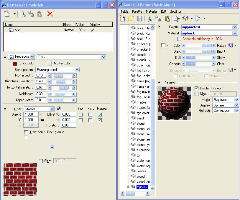
The rendering image with these materials may appear as indicated in the following image.
12. CREATE MATERIAL TYPICAL PROCEDURE
A more typical procedure for creating materials relies upon simple bump map definitions and attribute values to arrive more abstractly at the definition of materials. Under Settings/Renderings/Materials (or via the dialog boxes above)
- Go to Palette> New and save “grue.pal” (can right-click to save or rename).
- Start new material “grue1” by right-clicking on the palette and clicking “new material”.
- Pick base color by clicking on the white square next to color.
- Adjust sliders for: Ambient Diffuse Specular Finish Transmit Reflect Refract.
- Add bump map by clicking on the “pattern” button and switching the “Map” to “bump” (Use StuccoBump.jpg from bump directory).
- Reduce height to 0.50.
- Resave palette.
- Open up assign materials dialog box (Material>Assign).
- Open palette “grue”.
- Assign grue1 to cone.
- Render.
- Save the material table and palette files to reserve for next time.
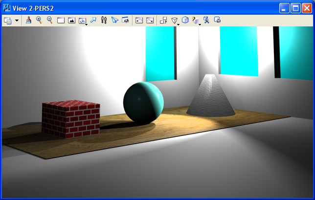
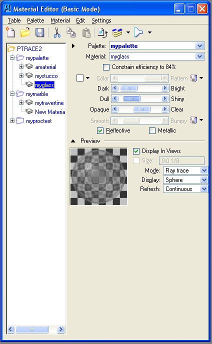
13. TRANSPARENT OBJECTS
- Setting the transparency value of an image can be used to render glass.
- Create a material glass in "mypalette", increasing transparency and turning on reflectivity.
.
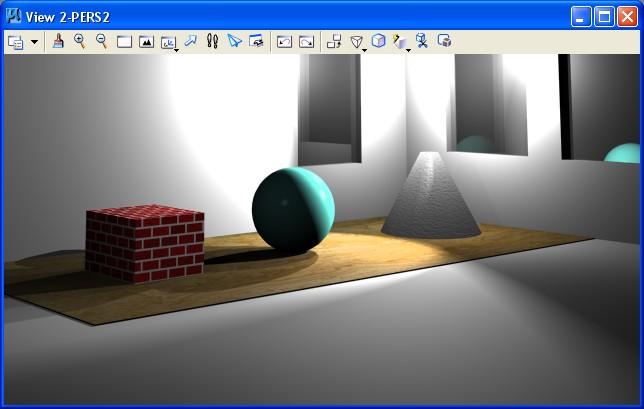
- Assigning glass to windows in the dgn file creates the following rendering.
14. TO MAP IMAGE
- In the new palette, right-click for “new material”.
- Hit the “Pattern” box.
- Click on the magnifying glass to browse for image.
- Turn off transparent background.
- Under “units” make sure it is assigned to “surface” to stretch the image to the surface area (“Master” tiles it in 1’x1’ modules).
- In the model, build a new rectangle in a new color.
- Assign image to rectangle.
- Render to view.
15. ENVIRONMENTAL MAP
Table>environment maps
- Set environment maps (use SkyBlueSmClouds.jpg).
- Select “raytrace.pal” and assign mirror to rectangle.
16. SAVING RENDERINGS (From before)
- V iew size in Settings>Rendering>View size.
- Set to 640x480 (make sure “proportional resize” is off).
- Save image file by going to Utilities>Image>Save (check options and save by browsing to folder).
- To see image in microstation, go to Utilities>Image>Display .
17. PARTICLE TRACING / RENDERING
- Open ptrace2/ptrace-still.dgn
- Change to modest view size (settings/render/viewsize)
- Set the view size to 640 x 480
- Fit view
- Click on the B symbol at the top of the working window and select “view attributes”>turn on constructions . . . see lights in the file
- Turn off constructions
- Alternatively use settings/view attributes/constructions on … see two point & two spot lights
- Settings/view attributes/constructions off …
- Change render mode to particle trace
- Select magnifying glass (particle trace dialog box) and use “Advanced Settings”
- See handout on class website for settings
- http://archweb.arch.virginia.edu/arch541/Handouts/render/ptrace.html
- Goto Utilities/Saved Views and select PERS2
- Click on global lighting/turn off ambient/flashbulb/solar lights
- Also, use tools/visualization tools/rendering tools (modify/edit light) … see lights listed and values
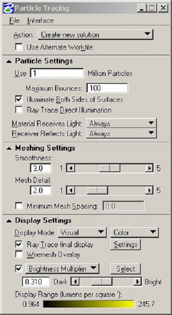
18. BASIC SETUP
- Advanced Settings - Dialog Box for Particle Tracing
- Action - current, new, augmented solutions
- Particles - number of particles to shoot (begin 1 mil)
- Maximum Bounces - number of times to bounce each particle (avg 100)
- Illuminate Both Sides - Turn off if non-illuminated surfaces are not to be rendered (typically on)
- Ray Trace Direct Illumination - Alleviates mulitple shadows computing shadows from light sources not reflected light - (typically off as disrupts realism)
- Meshing - smooth, smaller values produce sharper shadows, but can introduce noise, higher values produce smoother shadows, but can be blurry if value is too high
- Mesh Detail - resolution of rendering mesh, higher values produce more accurate results at greater cost in computational time
- Minimum Mesh Detail - in Master Units, specifies minimum size of smallest feature visible in solution (typical leave this off)
- Display - Render result either in photorealistic image - raytrace or show illuminance (energy hitting surface “incoming”) or luminance (energy reflecting from surface)
- Brightness Multiplier – Aperature Long From (choose via interface)
 |
Action |
Use old, update, or generate new solution., save solution |
Particle Settings |
# particles to use (1 mil) |
Maximum bounces |
# times bounce (100 avg) |
Illuminate both sides |
Sometimes surfaces may be non-illuminated (best to default this on) |
Ray trace direct |
Will alleviate multiple shadows, saves time, not good idea to use this in general |
Meshing settings smoothness |
Breakdown
of mesh to effect smooth surf –noise to smooth |
Mesh detail |
Level
of resolution at key places – higher no. -> higher quality |
Min mesh setting |
Higher # improves perform at low resolution |
Display mode |
Visual, luminance (outgoing),illuminance (incoming) |
Raytrace final display |
Render using raytracing. |
Brightness overlay |
Aperature. |
|
- Try settings
- Action: create new solution.
- Use 1 million particles.
- Max bounces: 1 million.
- Illuminate both side surfaces.
- Ray trace direct illumination (off)
- Material Receives/Reflecrts light (always)
- Meshing settings (Smoothness 3, Detail 3)
- Min mesh spacing (off)
- Display mode: visual/color
- Raytrace final display (on)
- Wiremesh overlay (off)
- Brightness multiplier (as is)
- RENDER
- Use brightness multiplier select tool/select hot spot/rerender
- Add more particles and render again (can take up to 20 million to get correct light intensity).
- Illuminance / Luminance
- Change to illuminance (incoming light energy)
- Action: Display current solution
- RENDER.
- Change to luminance (reflective light energy)
- Action: Display current solution
- RENDER.
- Adjust Brightness of Current Solution
- Change to visual display
- Add sunlight on.
- Action: Create new solution (or load existing solution ptrace2.ptd if time short)
- Add sunlight on.
- Try brightness multiplier 3.94? or
- Use elect tool, make dark surface area the average
- RENDER
- Zoom up and re-render “same solution”. (note the time-saving aspect of particle tracing – once a solution is created it can be reused from any view angle with great efficiency.)
- Action: lower brightness and display current solution
- Lower Brightness multiplier: (0.16), or
- Sample hot spot – alt option.
- RE-RENDER
- Add background image (doesn’t really effect energy solution)
- Settings>Design File>Views>Select background.
- Magnifying Glass>Triforma TF Imperial Pattern
- Load sky blue with clouds
- Action: display current solution
- RE-RENDER
- Save solution (ptd particle trace solution file)
- Reload solution note again the time-savings aspect of particle tracing – once a solution is created it can be reused from any view angle with great efficiency.
19. Download IES files and test as attached to point source light in new dgn file.
- Download from classes/examples: ptrace/ptrace2/test-ies.dgn
- See rendering and lighting IES Data handout.
- Use 0775FRIES {Lightolier/12” handing pendent/incandescent.
- With two point source lights/ and 0755FR.IES and 0584FR.IES data sets for 12” pendentive and 12”pendentive with aluminum reflector - 150 Watt bulbs.
- Load shp file … Do current particle trace solution or make new one.
- Adapt to brightness as necessary
- Note, in any new dgn file, you could create
point source light with IES data from web, site such as http://www.lightolier.com
- See Also http://www.lighting-inc.com/searchman.html, http://www.hadcolighting.co
- IES Data: Manufacturers provide
this data on spread and intensity of light that can be substituted for
lighting setup parameters. Should be used on point source lights only.
- Illuminating Engineering Society
(formed in 1906) (IESNA/IES) –Included Honory member Thomas Edison.
20. PARTICLE TRACING - OVERALL CONCEPTS/FAQ
EXCERPTED FROM BENTLEY'S MATERIALS
Question 1: How do I get a "good" particle Trace solution?
Answer : There are several different ways to achieve better results when we Particle Trace render. Below are a few ways to accomplish this:
STEP 1: Raytrace
- First thing to do is open the rendering tools, and render the scene using Raytrace to see what the scene looks like currently, but be sure to turn off ambient and flashbulb lighting. If the scene does not look good in Raytrace, then chances are it is not going to look good in a Particle Trace solution. It may be too dark, then we need to address the lighting by adding more natural light. If the scene is brighter than desired, then the lights need to lessen by lowering the intensity. So when the scene looks well lit and everything is in clear view.
STEP 2: Particle setup
- Use the default settings first, to see what you get.
- 1. million particles
- Mesh smoothness on 3
- Check off "RayTrace Final Display" so we can see the results faster.
- To speed up the process, check on "Raytrace Direct illumination" in the Particle Trace setting dialog box. With this setting checked on, the raytracer will compute the shadows from the light source, but not the reflected light.
STEP 3: Brightness
- The first rendering may appear darker than the Previous Raytrace rendering.
- This can be fixed by adjusting the brightness multiplier.
STEP 4: AMP (Add More Particles): Add more particles if:
- There is tiling or faceted elements then more particles are needed (some edges can not be smoothed if the angle is too sharp).
- There are color blotches randomly in the scene.
- Try bumping it up to 5 million particles in the scene, but to do this efficiently, change the Action setting to "Add more particles and redo mesh" and set the particles to 4 million. Since there is already 1 million particles in the scene, adding 4 million more will give an even total of 5 million.
- It may look better, but it may not look good enough. Adding more particles is the best way to get the scene more convincingly rendered and more completely realized with respect to the distribution of light energy.
- If some elements do not smooth out then they probably will never smooth out enough. This is related to how the element was modeled.
- If the angles of the edges are too sharp they will be able to be smoothed out. It is like trying to smooth out a cube. Thus this is the best it will get.
STEP 5: Mesh smoothing
- To change the mesh settings, which will create more detail, first you need to click the Redo Mesh button, since you are not adding particles; you do not need to recalculate the shooting of the particles.
- Setting the smoothness setting to a lower value such as 1, the rendering, will be less detailed and the particles will spaced further apart, which can produce the colored spots. This is because the mesh is not as detailed and will not except as many particles; hence the colors become blotchy.
- The default setting of 3 may be good enough.
STEP 6: Final touches
- Once you are satisfied with the detail of the solution you can display the final rendering for the view by going to the Particle Trace settings and selecting "Ray Trace Final Display"
- Then select "Redisplay Solution and select the view to render the scene for a final rendering.
- This will combine the Particle Trace solution with a Raytrace rendering. The Particle Trace solution is not a rendering solution on its own. It is only a lighting solution.
- Raytracing the scene will display the highlights and reflections of the elements in the scene.
- Not using "Ray Trace Final display" speeds the time for the rendering process.
- This helps when you are only working on the Particle Tracing solution and not concerned with the display of the highlights and reflections.
Question 2: What settings values are recommended for the initial rendering?
Answer : Using the default settings is a good place to start, they are:
- 1 Million Particles
- Mesh settings/Smoothness of 3
- Uncheck "Ray Trace Final Display"
- Turn on "Ray Trace Direct Illumination" in the Raytrace settings NOTES ON RENDERING SETUP (rendering:general)
- shadow maps (see general ... leave off save shadow maps)
- anti aliasing grid side (draw pixels and diagonal lines)
- grid size 2 means 4 passes on a 2x2 grid
- 3 means 9 passes on a 9x9 grid
- stroke tolerance - maximum deviation of curve geometry from true pixel locations where all curves represented as polygons how many edges in polygon
- stroke tolerance override - maximum deviation of curve geometry from true pixel locations where all curves are represented as polygons in a working unit designation of distance rather than as a scalar
- shadow tolerance - how close shadows are to cast shadows prevents from objects casting shadows on themselves, higher values means lower accuracy
- shadow filter size - softness of shadows , higher value means softer shadow (describes number of pixels to look at in the shadow map) ... too large means no shadows, too small means objects cast shadows that conceal themselves.
SEE ALSO :
http://www.arch.virginia.edu/arch541/Handouts/render/attrib.html {material attributes
http://archweb.arch.virginia.edu/arch541/Handouts/render/rtraceset.html {raytrace attributes
http://archweb.arch.virginia.edu/arch541/Handouts/render/setup.html {gen render attributes
http://www.arch.virginia.edu/arch541/Handouts/render/viewatr.html {view attributes
http://archweb.arch.virginia.edu//arch541/Handouts/sample.htm {sample marble