ALAR 6712 Studio Workshop Spring 2012
Workshop 4 Notes, February 2, 2012
INTRO TO SURFACES IN RHINO, (EXTRACURRICULAR, NTRO TO FEATURE SOLIDS IN MICROSTATION & CONTRUCTION PLANES IN RHINO REVISITED)
1. SURFACES
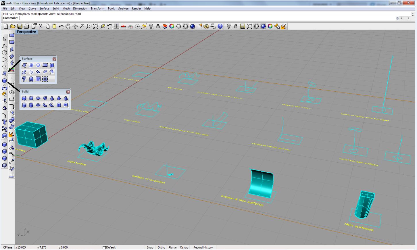
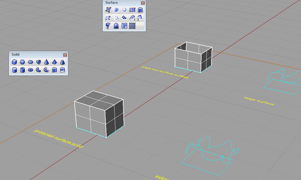
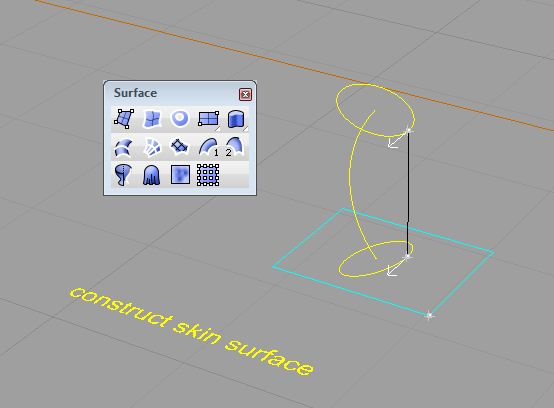
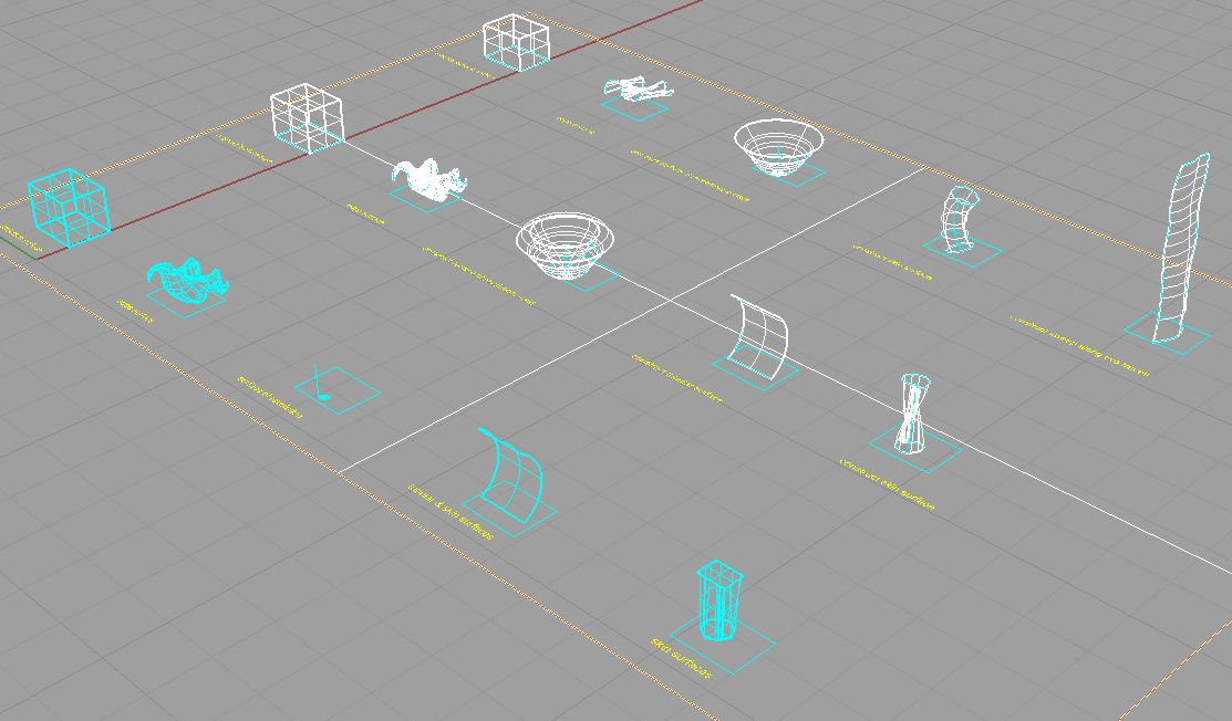
Load the file Classes\ALAR6712-Mark-SPR2012\Examples\surfaces\surfs.3dm. In the Main tool box, click and hold the surface icon to open up the Surface modeling tool box then click and hold the solids icon to open up the Solid modeling tool box, and use the tool specified in each case of a surface type entity as indicated below.

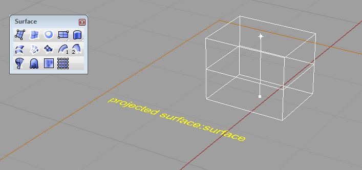
 |
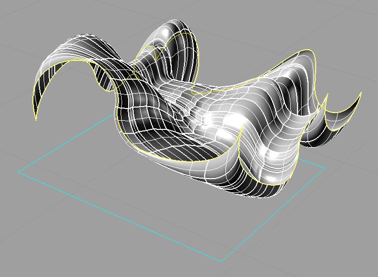 |
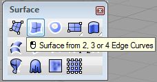
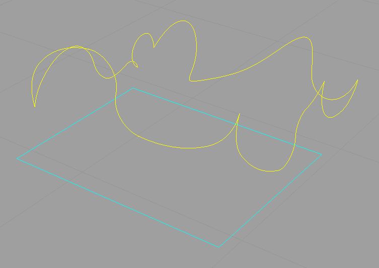
| select edges | generated edge defined surface |
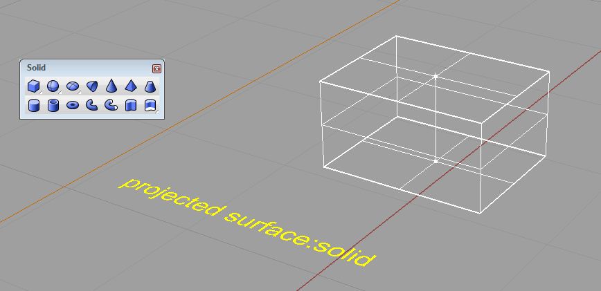
 |
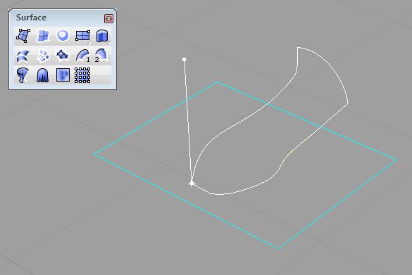 |
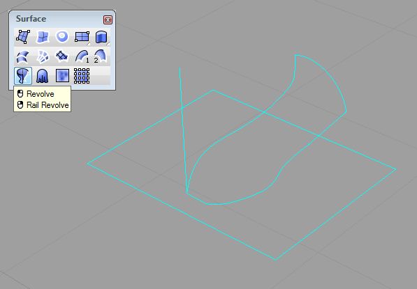
| Selecting Revolve from the Surface tool box. | Selecting the profile curve and then the bottom and top of the sweeping axis followed by enter to set the start angle. |
 |
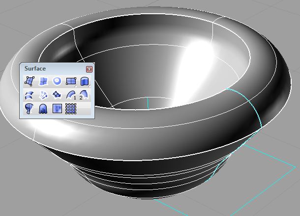 |
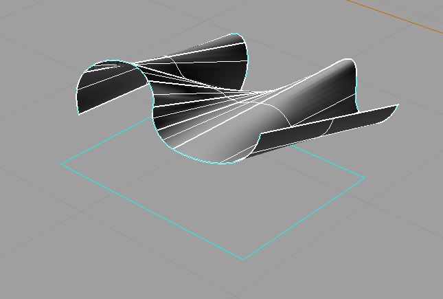
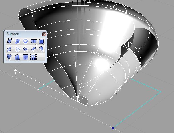
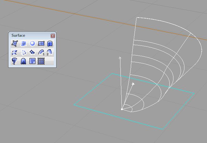
| Interactively sweeping the profile 180 degrees by moving the cursor (clicking now will create half the surface). | Pressing enter will automatically sweep the profile the full 360 degrees and complete the tool. |
 |
 |
| Selecting the profile curve and the upper and lower portion of the vertical then enter to create interactive sweep. | Pressing enter again sweeps out the full 360 degrees. |
 |
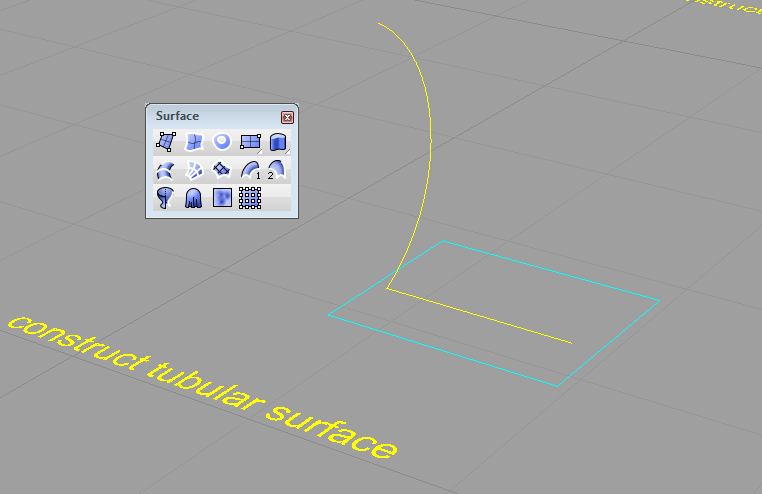 |
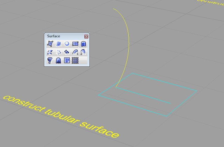
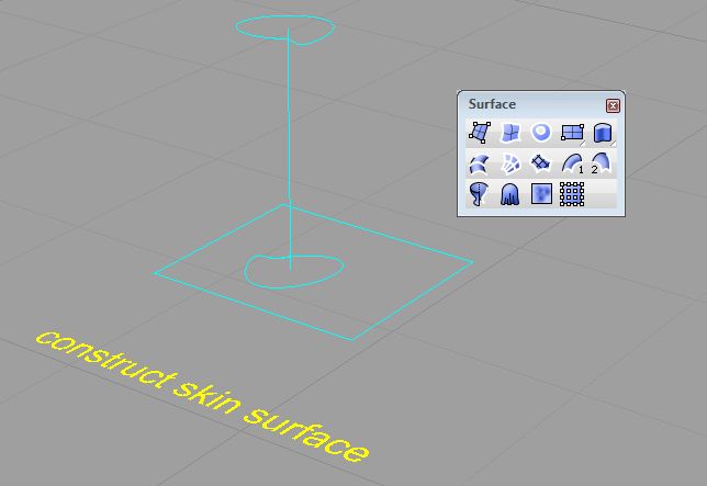
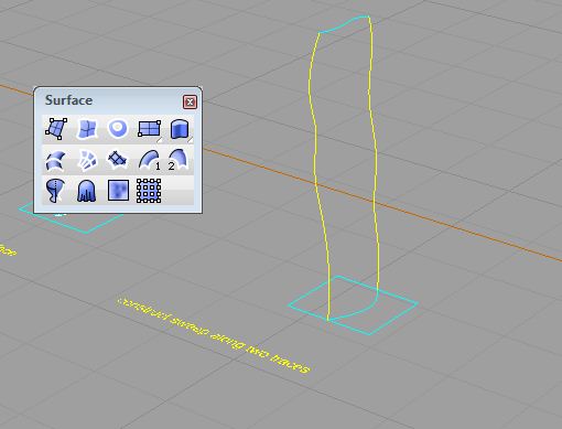
| Selecting the path curve first. | Selecting the profile curve on the ground second. |
 |
 |
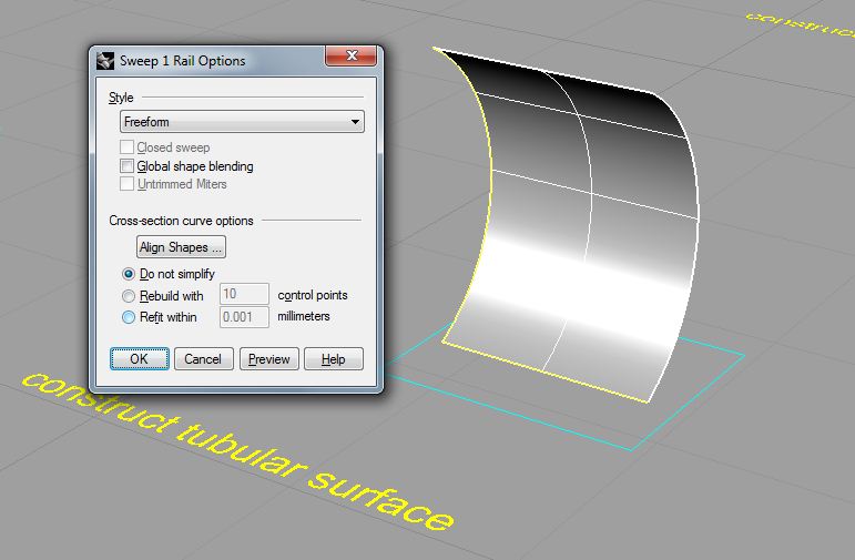
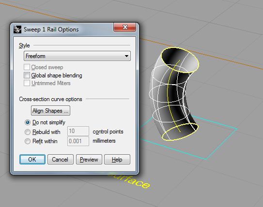
| Pressing enter will bring up an options dialog box. | Keep the original settings and press OK to generate the surface. |
 |
 |
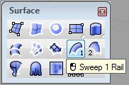
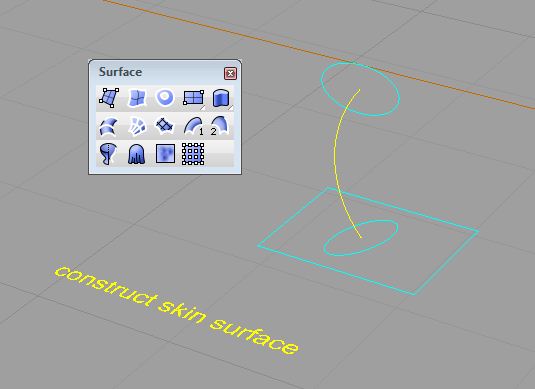
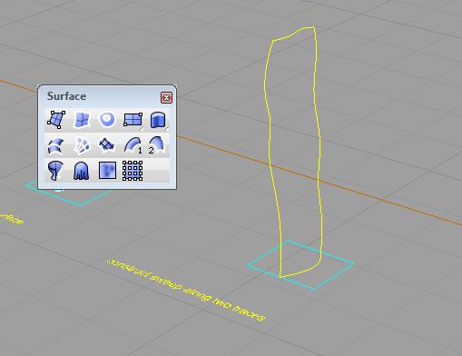
| The Sweep 1 rail icon is selected followed by the path curve | select the two profile curves |
 |
 |
| enter brings up the tool for adjusting the curve directions, make sure both arrows face the same direction. | enter again brings up the options dialog, press ok to complete the surface. |
 |
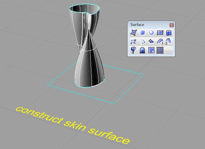 |
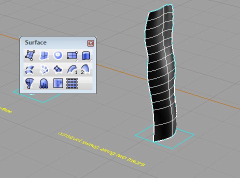
| The Sweep 1 rail is selected for the example above. | Select the two profile curves and enter to bring up the options dialog, enter again to complete the surface. |
 |
 |
| Select the Sweep 2 Rails icon | select the profile curves |
 |
 |
| select the end curves | Press enter to bring up the options dialog then OK to genterate the surface. |
 |
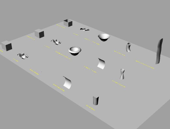 |
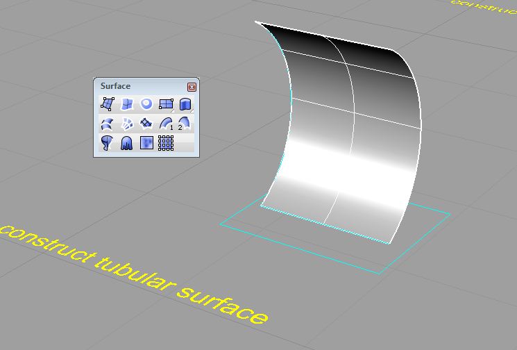
| surfaces in wireframe | surfaces rendered in Rhino renderer |
2. FEATURE SOLIDS OR SMART SOLIDS
Within Microstation is a method for modeling and manipulating solids parametrically. Start by opening up a new Microstation drawing.
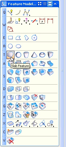
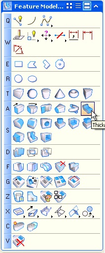
In the modeling tabs on the left select the Feature Modeling Menu and create a block with the Slab Feature tool (T1).
 |
|
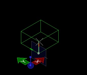
| In the Iso view click to drag out width, depth, and height. |
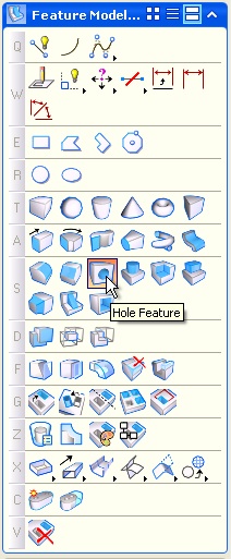
Now
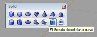
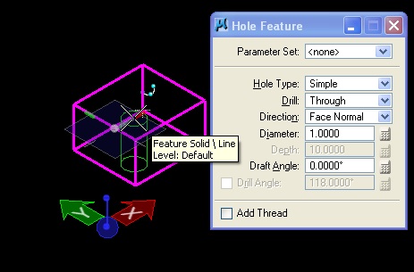
using the Feature Modeling Menu again enter holes in the slab using the
Hole Feature shown below (S3)
 |
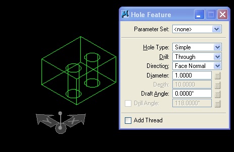 |
| First select the slab, then place the hole by clicking on one of the faces. | Right click to complete the tool, the Hole Feature dialog box can also be used to change the properties of the holes. |
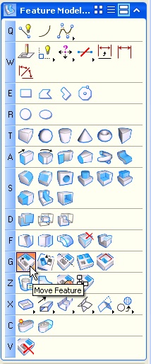
Move Holes
Select the Move Feature icon from the Feature Modeling tab (G1)
 |
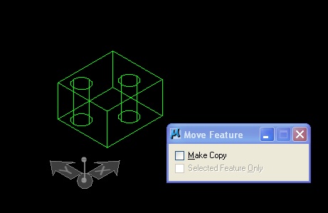 |
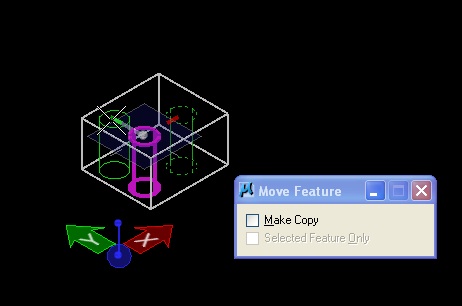
| Select one of the holes to move it within the slab. | Right click to complete the tool. |
 |
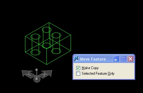 |
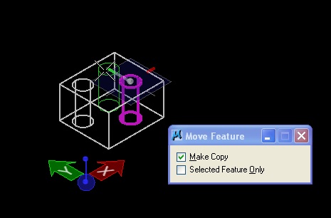
| Select the tool again with the Make Copy box checked. | This allows for the original hole to be kept. |
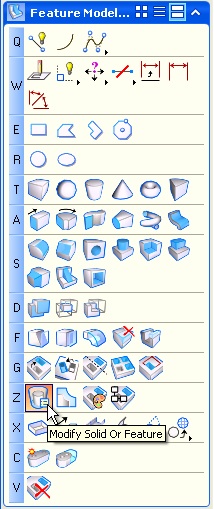
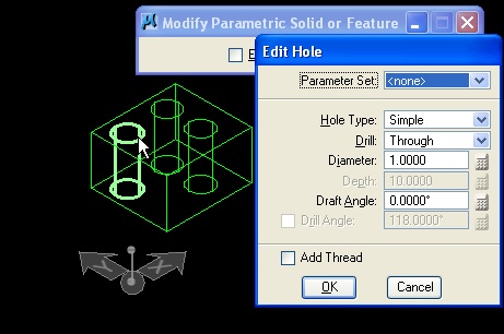
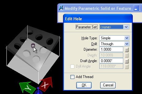
Modify Dimension of Holes
Select the Modify Solid or Feature tool as shown below (Z1)
 |
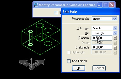 |
| Select one of the holes in the slab | Change the Diameter value in the Edit Hole dialog box and hit OK. |
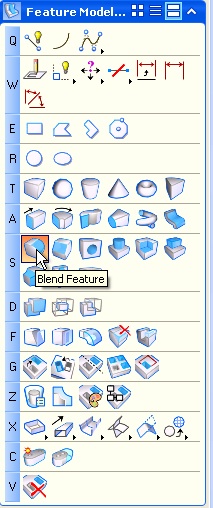
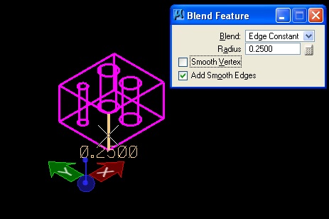
Modify Edges With Blend Feature
Select Blend Feature from the Feature Modeling tab (S1)
 |
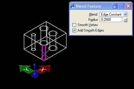 |
| Select an edge of the slab. | Click again to fillet the edge, and a third time to accept. |
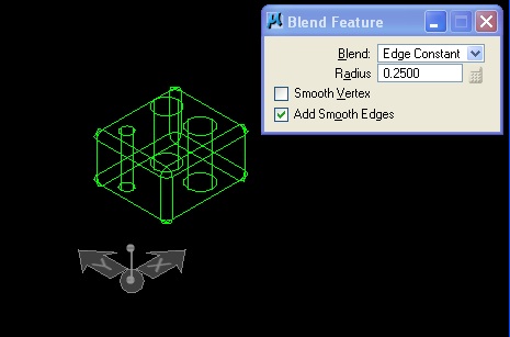 |
 |
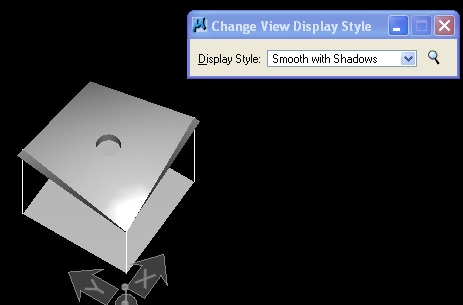
| Do this for all edges of the slab. | View changed to smooth with shadows. |
3. SIMPLE SADDLE REVISITED (FROM LECTURE)
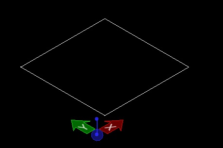
1. With ACS Plane Lock set to On, Create a 12 x12 rectangle (place block tool) in the ground plane.
2. Using the "F" front Accudraw rotation plane, create vertical lines in opposite corners at 7 and 11 feet high each.
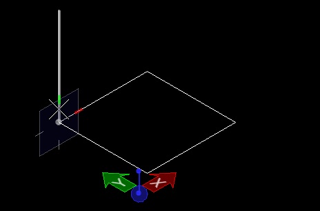 |
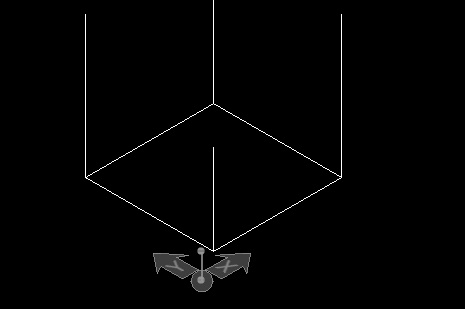 |
| Click a corner point then "F" to rotate to front view and draw the line. | Do this for all corner points. |
3. In the Sufaces Menu, generate a surface from four corner points.
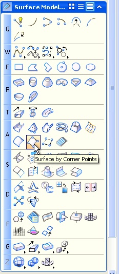
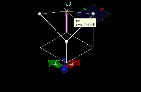 |
 |
| Click the tops of each line in clockwise or counterclockwise order. | Saddle surface in wireframe. |
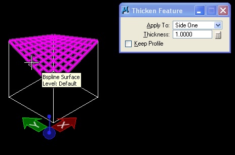
4. In the Feature Solids menu, thicken the surface 1.0 feet.
 |
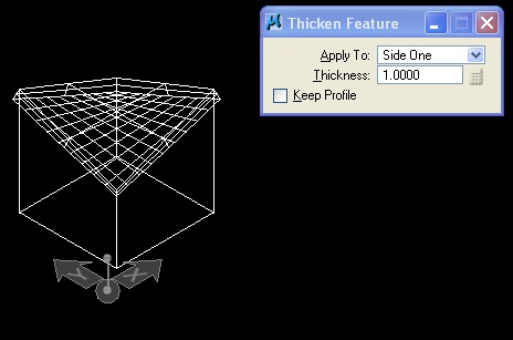 |
| Select the saddle surface, make sure the Thickness is set to 1.000 | Click above to create the surface. |
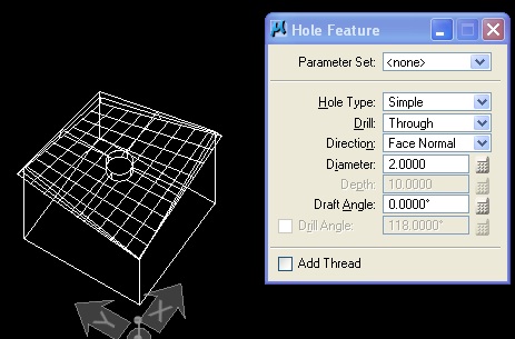
5. Add a hole to the center of the new solid, using the same methods applied to the slab above.
 |
 |
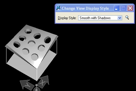
| Use the Hole feature and select the center of the slab with diameter 2. | Rendered in Smooth with Shadows. |
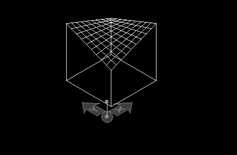
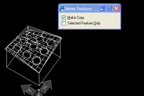
6. Copy the hole using the Move Feature tool, using the same methods applied to the slab above.
 |
 |
| Select the center hole with Make Copy checked. | Make a grid across the saddle slab. |
7.
Change the dimesions of the hole using the "Modify Solid or Feature"
tool, using the same methods applied to the slab in the earlier example.
 |
 |
| Select the center hole and change diameter to 1. | Click OK to accept. |
8. The same "Modify Solid or Feature" tool can be use to thicken the simple saddle roof.
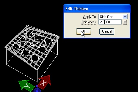 |
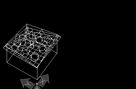 |
| Click on the edge of the slab with the Modify Solid or Feature tool. | Set the thickness and hit OK. |

4. . Coordinate Systems in Rhino
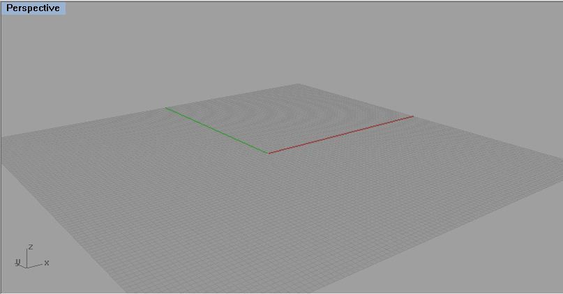
When drawing in Rhino, objects are snapped into a 2D invisible plane called a Construction Plane or CPlane. In perspective view if you are near the origin of the model space and grid is turned on (default) you can see the CPlane as the grid with the X and Y coordinates represented as red and green lines on this grid respectively. In the bottom left of this image is also an icon that shows the Global Coordinate System relative to the view window.
CPlane
= Construction Plane, the invisible 2D plane which data points are
snapped to. Changes relative to the different views.
Global Coordinate System = Represents the XYZ orientation of the model.
Does not change relative to the different views or CPlanes. By default,
it is co-planar with the CPlanes.
5. Manipulating CPlanes and coordinate systems.
1. CPlanes in Rhino can be moved or rotated to any orientation to allow for better control of drawing in the model space
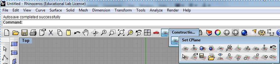
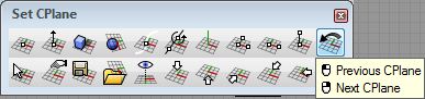
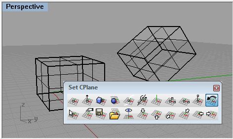
Setting CPlanes in Rhino
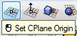
- Click and hold on the icon in the Main button bar called Set CPlane : origin to open up the Coordinate System bar as its own window. Then Click and hold the first icon in that bar to open up the Set CPlane bar as another independent window.
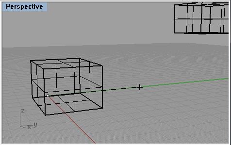
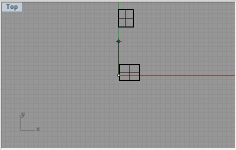
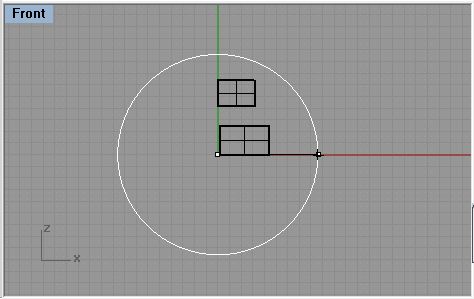
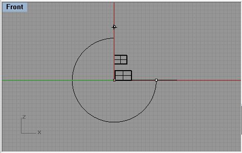
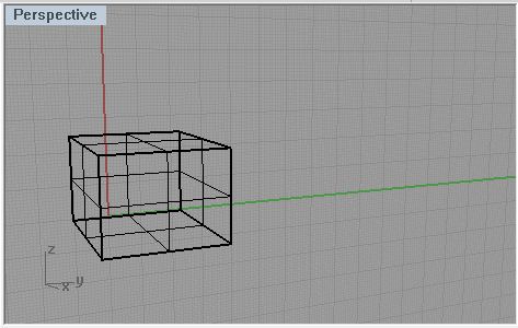
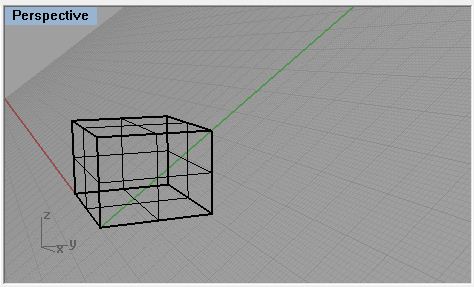
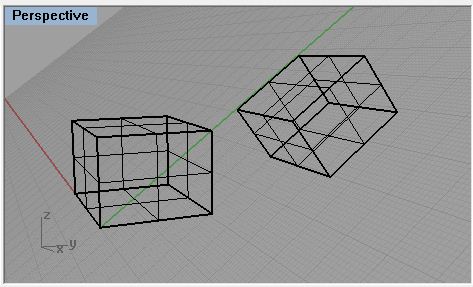
In perspective view draw a simple box, notice how the data points defining its length and width default to the Grid of the CPlane. Now draw another box starting in the side view away from the origin, notice its position once extuded in the Perspective view off of the Perspective CPlane.
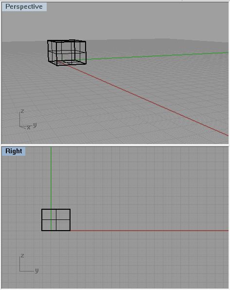 |
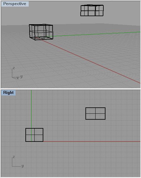 |
| Box drawn on CPlane in Perspetive view. | Box drawn on CPlane in Right view, is not snapped to perspective grid plane. |
1.1 Translating the CPlane
Click on the first icon in the Set CPlane menu box labeled Set CPlane Origin.
Then move the Origin of the CPlane in the perspective view anywhere in the model, even snapping to objects or other points. Now drawing in Perspective view will snap all data points to this new construction plane.
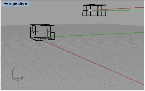

Moving origin to a snap point on another object.
At anytime click the icon labeled Previous CPlane to navigate changes made in the CPlane.
Returns to last Construction Plane used.
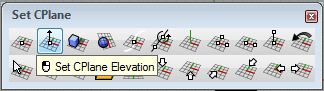
Use the Second icon labeled Set CPlane Elevation to just move the CPlane in its relative Z axis, and click to accept.
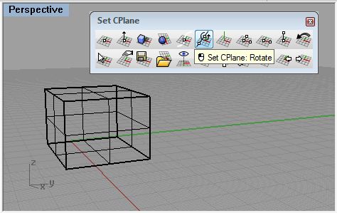
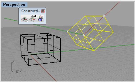
1.2 Rotating the CPlane
Use Set CPlane: Rotate to rotate the Perspective CPlane 90 degress about the Y axis.
 |
 |
| Choose Set CPlane: Rotate with the Perspective view selected. | Hit enter to set the rotation axis at the origin. |
 |
 |
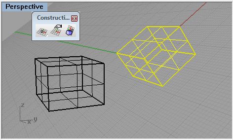
| With ortho on choose a point in Top view above the origin to set the axis. | In Front view click to the right with ortho to set the start rotation. |
 |
 |
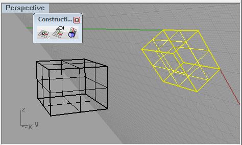
| Then click above to rotate the CPlane 90 degrees. | Now in the Perspective view you can see the grid is oriented in the ZY plane. |
Return to the original CPlane by clicking on the Previous CPlane icon.
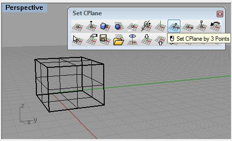
Next use the Set CPlane by 3 points icon to create an orientation relative to a diagonal on the box.
 |
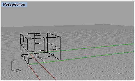 |
| With Perspective view selected click Set CPlane by 3 Points | With snaps on click on one corner of the box to set the origin |
 |
 |
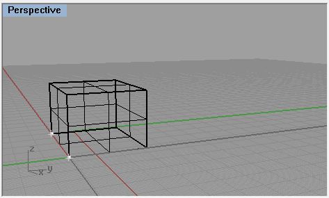
| Click on another corner to set the X axis | Then click on a third corner diagonal from the others to set the Y axis |
 |
 |
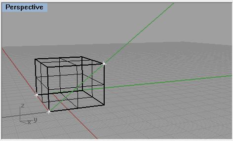
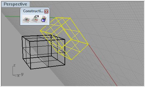
| This sets the CPlane through the box diagonally. | Drawing another box in Perspective view. |
Other methods of manipulating CPlanes.
Set
CPlane to Object
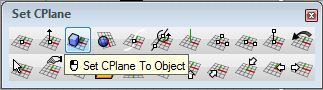
Sets the CPlane in-line with a part of an object, with the origin at
the object's center.
Set
CPlane to Surface
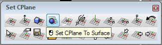
Sets the CPlane tangent to a point on an object's surface.
Set
CPlane Perpendicular to Curve
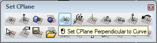
Sets the CPlane's X and Y axes perpendicular to a point on a curve.
Set
CPlane to View
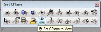
Creates a CPlane relative to the camera's viewing angle
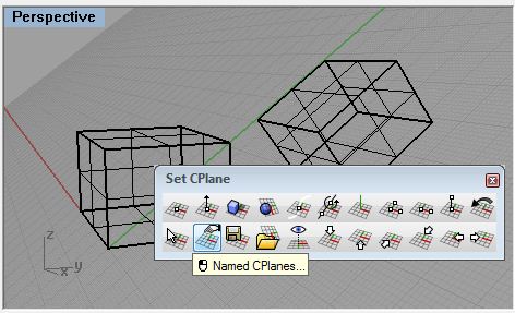
2.1 Organizing created Coordinate Planes.
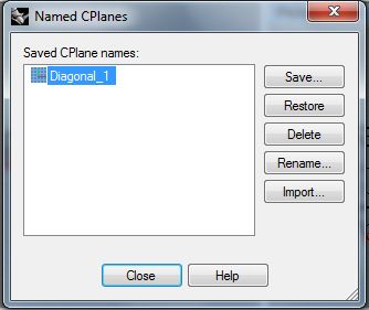
To save and load CPlanes.
 |
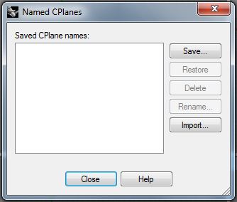 |
| Select the view and click Named CPlanes... | this brings up the Named CPlanes dialog box |
 |
 |
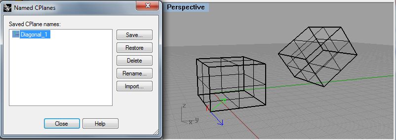
| Click Save and type in a name for the CPlane then hit OK | now the CPlane "Diagonal_1" can be referred back to later on. |
 |
|
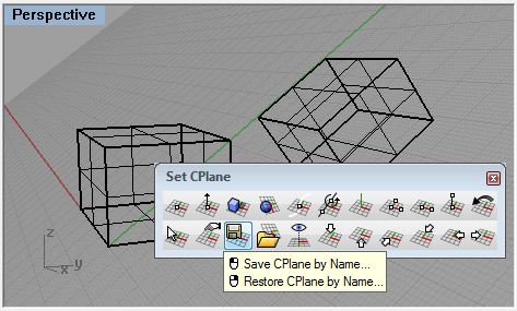
| Alternately you can click the Save CPlane by Name icon, type a name and press enter to save the selected view's CPlane. |
The
Named CPlanes dialog box can be used to restore saved CPlanes to the
selected view by choosing the view and clicking Restore.
the highlighted CPlane is displayed in the view window as colored
arrows.
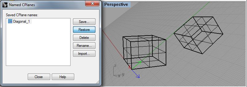
Clicking Restore applies the selected CPlane to the Viewport.
An alternate method to this is to right click the Save CPlane by name icon and type the saved CPlane's name then press enter.
2.2 Preset CPlanes.
![]()
These six icons in the bottom right of the button bar will apply a
CPlane to the selected view that is relative to
the Global Coordinates :Top, Bottom, Front, Back, Right, Left
orientation respectively. This is an effective way
to pull up normally used construction planes quickly and easily in the
model space.
2.3 Mobile Construction Planes
A last method of manipulating the Construction Planes is to attach it to an object and have it always update relative to that object.
 |
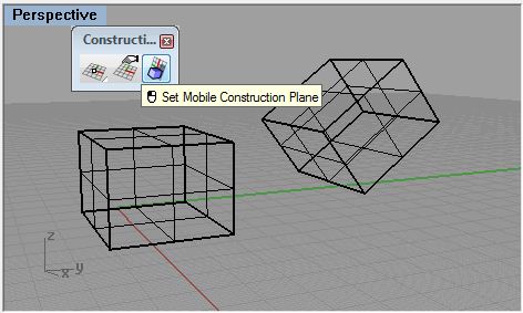 |
| In Perspetive View use the Previous CPlane icon to return to the default. | In the Construction Plane tool box click Set Mobile Construction Plane |
 |
 |
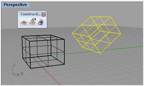
| Select the diagonal box and press "A" enter to attach | select one corner on the box to set the origin |
 |
 |
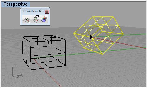
| select the other two corners to set the X and Y axes | Press enter for automatic updates to the CPlane. |
 |
 |
| Rotating the object rotates the attached CPlane as well | Translating the object will translate the CPlane |