COMPUTER
AIDED ARCHITECTURAL DESIGN
Workshop
8 Notes, Week of October 15, 2012
Lighting, Global
Illumination Rendering,Texture Mapping and Procedure
Mapping
NOTE: To initiate
this
workshop, you can build the file below in Rhino or copy the fie
"Arch3410-6710-Mark-FAL12\examples\rendermodel\stillLife.dgn" and the
folder "Arch3410-6710-Mark-FAL12\examples\materials".
1. BASIC LIGHTING
SETUP
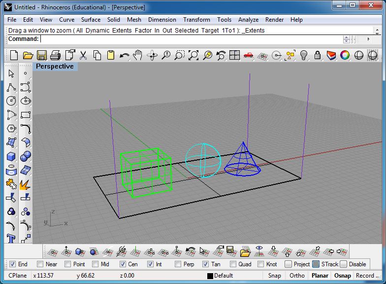
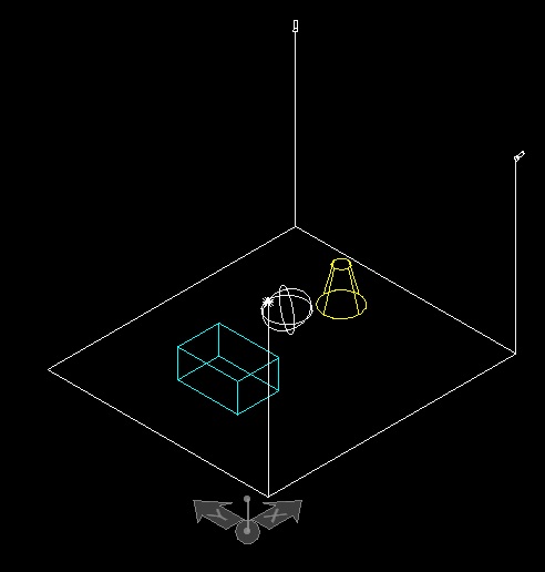
- Create the file
stillLife.3dm in Rhino with a flat plane and three solids. Add three
vertical lines at the corners as shown below
- Note, the process
is simpler
if you hold off on assigning color directly to objects until entering
into Microstation. Assign the objects to separate levels in
Rhino.
- Open the file in
Microstation.
- Save the file to
stillLife.dgn Microstation format.
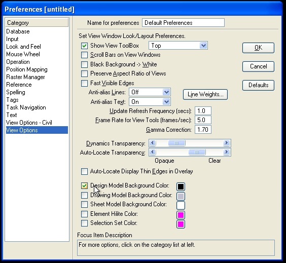
- Change the
background to black via the workspace/preferences/viewoptions menu.
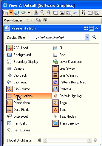
- Turn on the view
attribute "constructions" from the upper-left hand corner of the active
view angle.
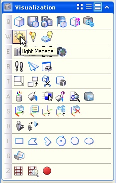
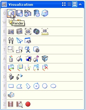
- Enter the light
manager W1 tool in the Visualization task.
- Place a rectangle
on
the ground, and then in separate colors a cube, sphere and truncated
cone.
- Add a vertical
line to
front-left, front-right and back right corners of teh rectangle on the
ground.
- Add three
vertical lines and then two spot lights and one point light to the
model
- Turn off the
"Constructions" in the view attributes
dialog box.
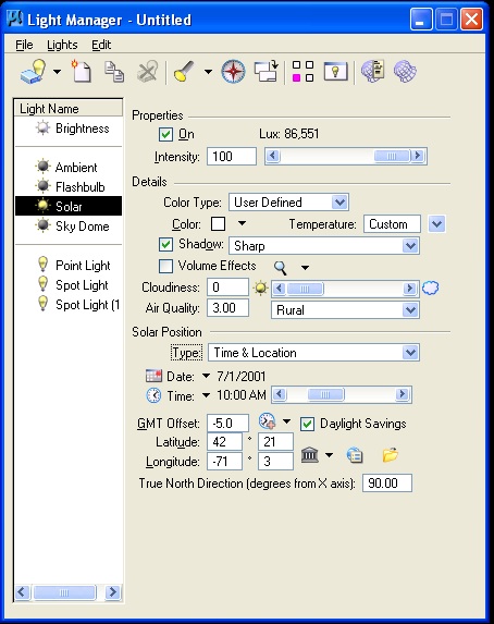
- Check
Settings/Rendering/Global lighting.
- Turn off Ambient,
Flashbulb and Solar light by removing the check from the check-box
"On" in the dialog box below OR by double clicking on the light symbols
to turn off the ambient, flashbulb and solar lights (shown as "on"
below), and ensure that the point light and the two spot lights are
turned on.
- Under View
attributes, turn off constructions so as to hide the light fixtures
(the lights will still impact the rendering of the model) and to
prepare for rendering the model.
3. SETTING THE
VIEW SIZE
- Get the View size
through the Microstation menu sequence
Settings>Rendering>View size.
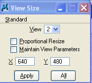
- Select the
"standard" menu and select mid-resolution 640x480
- Turn off "
proportional resize"
4. LUXOLOGY
RENDERING AND SAVE DIALOG
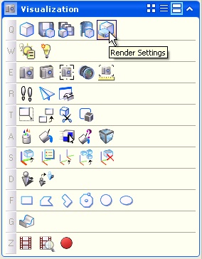
- Select the "Q1"
tool in the Visualization Task.
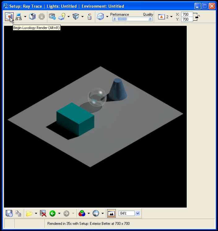
- Within the
Luxology rendering window, choose the Raytrace rendering option.
- Note that an
earlier rendering will first show up in the rendering view window, not
necessarily your current model.
- Image size is
given in pixels in the upper right-hand corner at 700 pixels by 700
pixels (release padlock to set X and Y independently).

- The view number
"2" is indicated to determine which view is to be rendered.
- Initiate the
rendering.
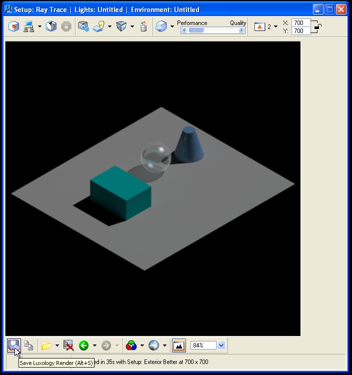
- Use the save file
icon in the lower left hand corner of the Luxology Rendering Window.
- Note that file
type is set to jpg a "pseudo" 24 bit color format to optimize file size
against image quality, adequate for school related uses and recommended
for making files portable.
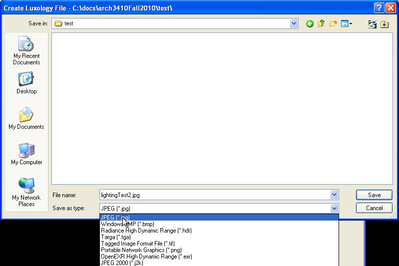
- Alternatively
"tiff" format, true 24 bit color, is recommended for higher
color quality used in professional printing.
- Selecting the
"Q4" tool, each of the rendering types can be optimizied by determining
the appropriate parameters for each.
- For example,
antialiasing quality is set to "Medium" which optimizes quality against
renderint time. A setting of "Very HIgh" which requires more rendering
time.
- For each
attribute on the three tabs "Settings", "Global Illumination", and
"Advanced", there is often a trade off between rendering quality,
realism, and rendering time.
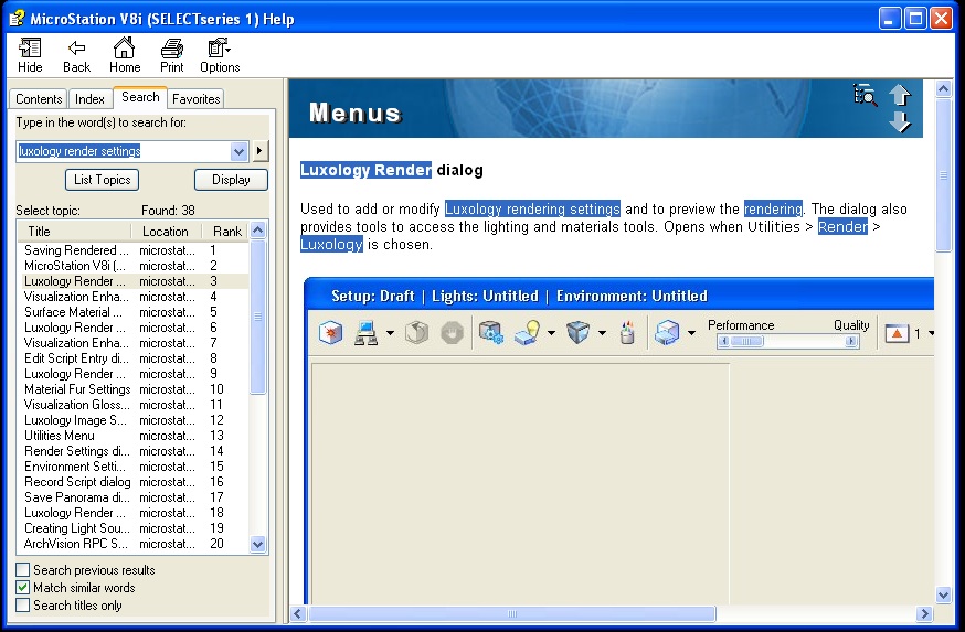
- A discussion of
each rendering setup is beyond the scope of these workshop notes, but
has been referred to in part in the general overview just before the
fall break. The Microstation Help dialog box also contains specific
information about each setup. For example, go to the Help/Contents
Menu, and initiate a search on "luxology render settings". Look at the
3rd item "Luxology Render dialog".
- To see image in
Microstation, go to Utilities>Image>Display .
5.
FILE
TYPES FOR MATERIALS
(REVISITED)
The Materials
Table, Palette and individual images used to define materials can all
be potentially saved as external files so as to be able to be
used in other drawing files. When the external file saving option is
used, then these file types have standard naming extension formats:
Materials Table
(file extension " .mat" if saved externally)
- References the
palette files and tracks assignment of individual materials.
Material Palette
File (file extension " .pal" if saved externally) –definition
of materials. Can
be one of three types
- Definition by
properties [e.g. color]
- By procedure [by
specific algorithm]
- By texture
mapping [literally draping image onto a surface]
Material
Photographs
- for using real
photographs of materials or people, usually jpg or tiff files are also
included in the files needed to define materials (see classes folder
Examples\Materials).
6. SIMPLE
MATERIAL ASSIGNMENTS (REVISITED)
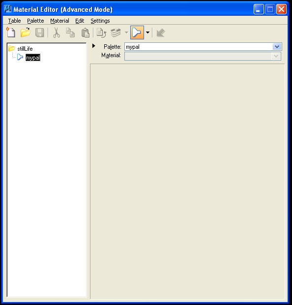
Go to the Define
Materials Icon in the Visualization task:
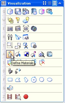
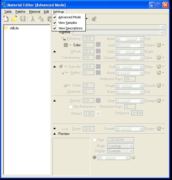
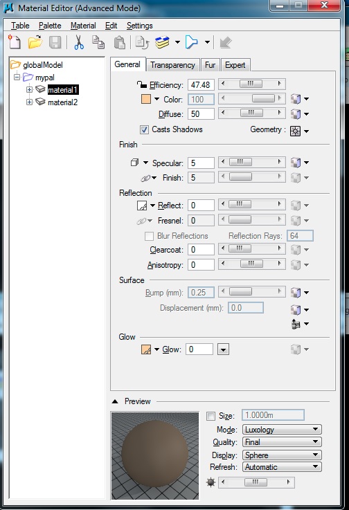
- The "Define
Materials" icon will open the Material Editor. Turn on all the settings
"Advanced Mode", "View Samples", and "View Descriptions" as depicted
below.
- Go to
Palette>New menu, create a new palette and name it "mypal"
- Right click on
mypal, select "new material", and name it "grue" (this is an arbitrary
name)
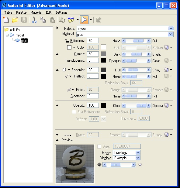
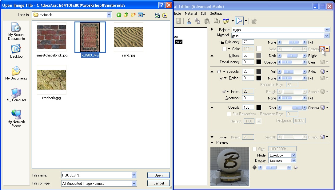
- Right-click on
the pattern check box, and find your way to the materials folder and
select the jpg file name rug03.jpg.
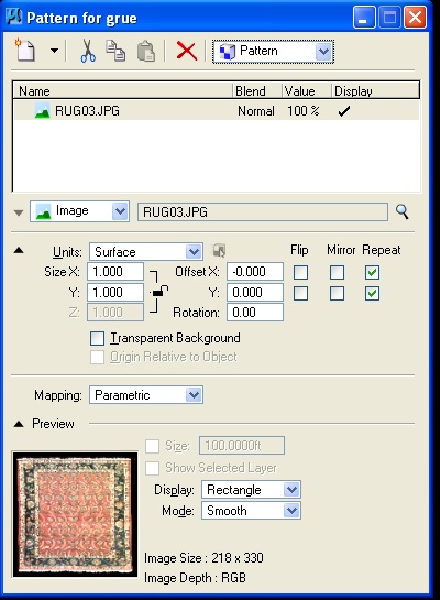
- In the "Pattern
for grue" dialog box that follows, the jpg file is sized to the Units
of "Surface" and will stretch to any surface onto which it
may apply. This is the default setting which is OK for this example.
Select the "x" in the upper-right hand corner of the dialog
box to go back to the Material Editor window:
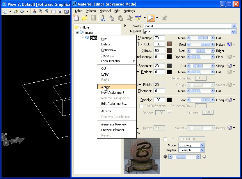
- Right-click on
"grue" in the Material Editor dialog box, go to " Assign," then choose
the rectangle in the ground plane from the drawing view window. The
material should then have a " +" next to it and contain the layer and
color of the object selected.
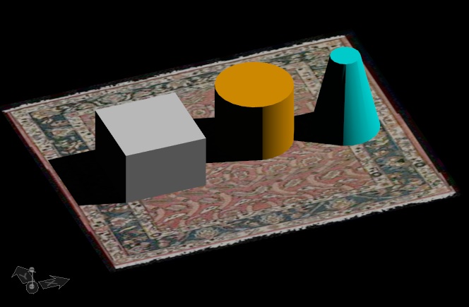
- The model will
then render in raytrace mode with the rug showing as follows:
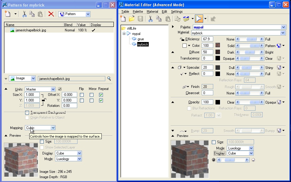
- Create a second
material named "mybrick" and
use the "Pattern
for mybrick" dialog to choose the material
"jamestchapelbrick", and set the size to "master", and the Mapping to
"Cubic"
- Then rendering
will now be as follows:
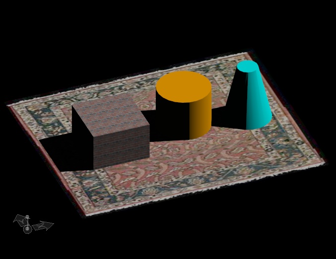
- Note that there
are some problems with the texture map for brick as captured in the
initial photograph. The brick appears self-evidently to be repeating as
applied to the cube in a way that seems artificial. For a more
realistic rendering of brick, a procedure map (an algorithmically based
description) of brick is used as an alternative.
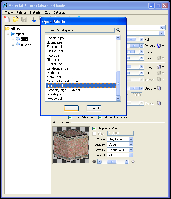
7. PROCEDURE TEXT
FILE
Go the the
Palette menu and use the "load" tool to open the palette named
"proctext.pal"
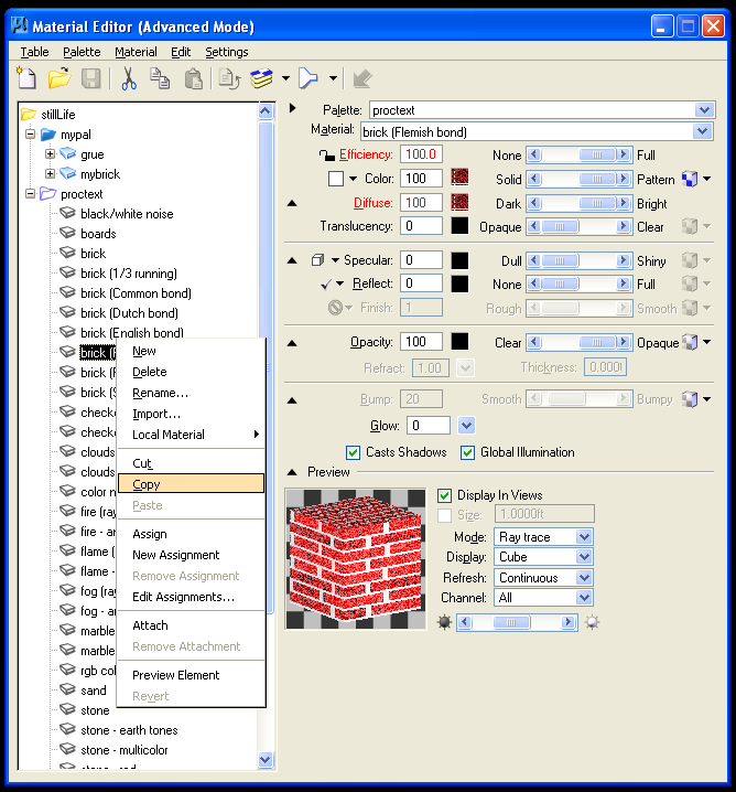
- In order to
preserve the system version of this palette, it is useful to save a
uniquely named copy.
- Right-mouse-button
click on the name proctext in the "Material Editor" dialog box and use
the "Save As" option to save it to a unique name such as
"myproctext.pal". Any material to be used should also be
copied and renamed as in the next two steps.
- Right-mouse
button click on the material "Flemish Bond" and select the copy option.
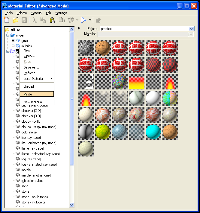
- Right-mouse click
on the palette name "myproctext" and select the paste.
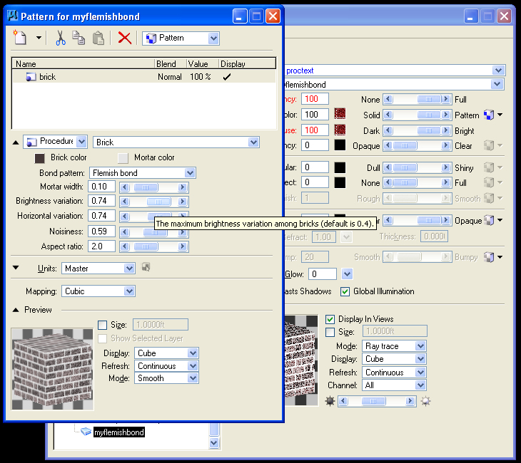
- Rename the
material "myflemishbond" and then select the color square on the right
hand side of the dialog box.
- Select the box
adjacent to the word "Pattern" to begin to edit the parameters for the
procedure map.
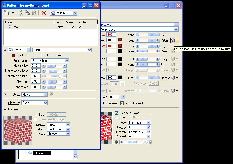
- Change the
"Units" to "Master" so that the pattern maps to one square foot.
- Change the
"Mapping" to "Cubic" so that the pattern projects
appropriately on to the cube.
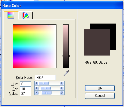
- Select the "Brick
Color" box, and lower the "value" and lower the "saturation"
of the color.
- Increase the
"Brightness variation" to accentuate differences in dark and light
colored brick.
- Increase the "Horizontal
variation" to give an uneven look to the horizontal grouting.
- Increase the
"Nosiness" to establish a more weathered look.
- These adjustments
are evident in the Preview window below.
- Assign the brick
to the cube in the Microstation drawing and render a quictk test with
"Antialiasing" set to "none".
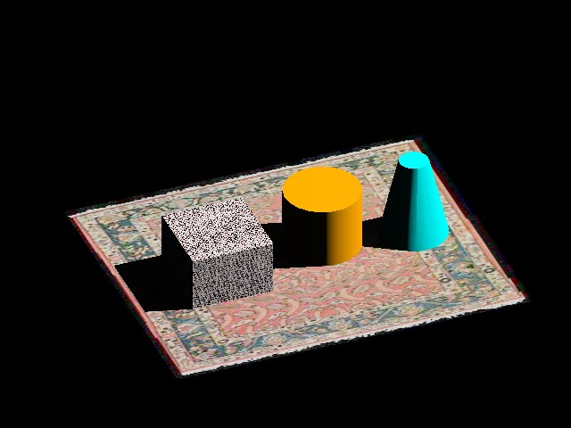
- The
apparent imperfections of the brick rendering can be
addressed by fine tuning the ray trace settings.
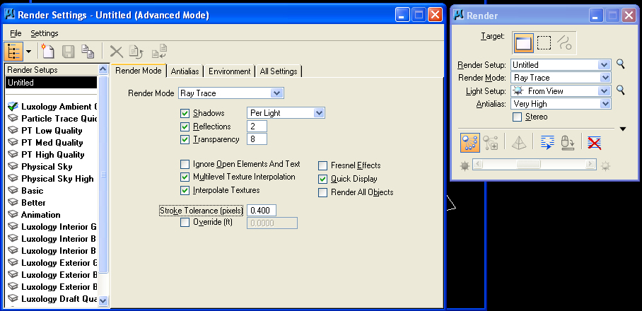
- Select the
magnifying glass icon next to the word "Untitled" in the Render dialog
box, to view the ray trace settings.
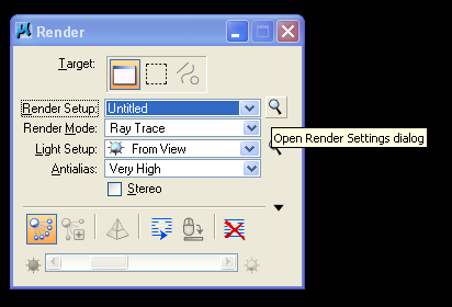
- Within the Render
Settings dialog box below, select "Settings" and select
advanced.
- In the "Render
Mode" tab, turn on "Multilevel Texture Interpolation" to improve the
rendering of the flemish bond.
- Turn on "Quick
Display" so as to render the image in several passes rather than at
once. This allows you to abort a rendering by rick-mouse-click in the
view window before it is fully executed and will save time if it
appears that the rendering is not likely to achieve the results you
want.
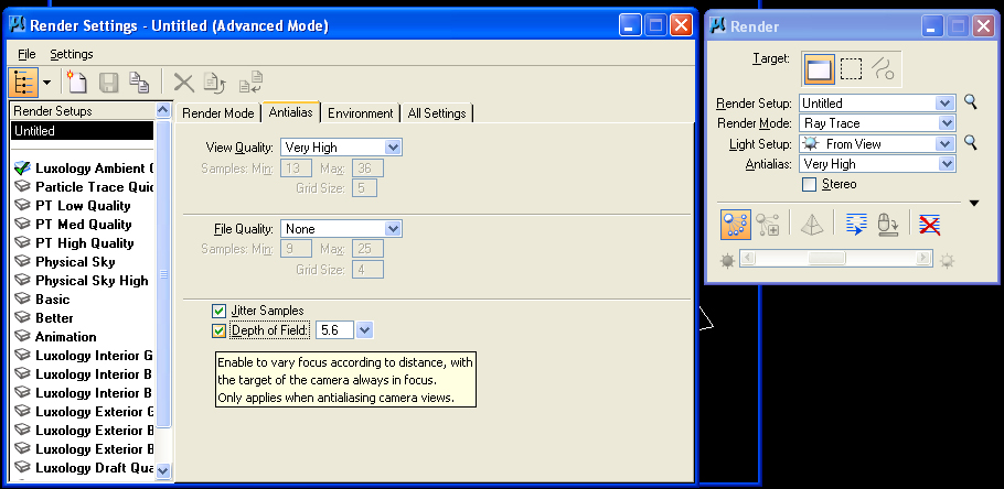
- In the
"Antialias" tab, set "View Quality" to "Very High".
- Set "Jitter
Samples" to on.
- Set "Depth of
Field" to on to simulate the depth of field effect in a photograph and
also set the FStop value to also simulate this setting on a camera. The
FStop is set to 5.6 in the example below. (The lower the
FStop value, the more open the camera aperature and the lower the depth
of field).
- Re-render the
image to see the change in quality as realized through the above
adjustments.

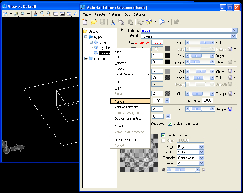
- Right-mouse-click
on "mypal" and create a new material "mywater" in the palette "mypal".
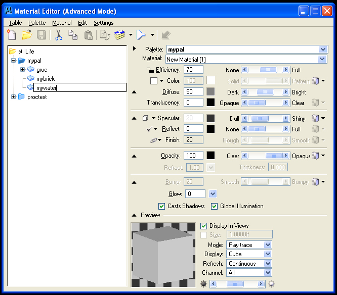
- Change the color
to dark gray, lower the "Diffuse level light towards "Dark", increase
the "Specular" level towards "Shiny", increase the "Reflect level"
towards "Full", and decrease the "Opacity" level towards
"Clear".
- Change the
preview "Display" type to "Sphere".
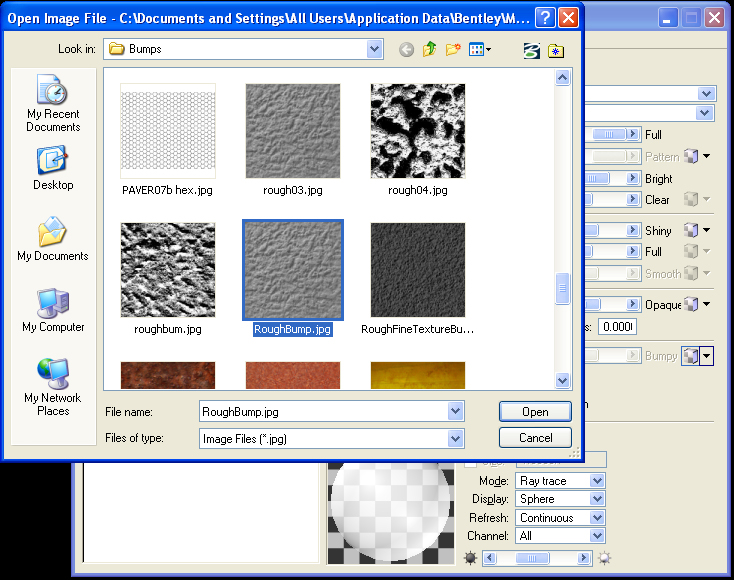
- Add a "Bump" map
such as "RoughBump" by selecting the box icon adjacent to the word
"Bumpy".
- Right-mouse-click
on "mywater" and apply the material to the ground rectangle in the
Microstation view window.
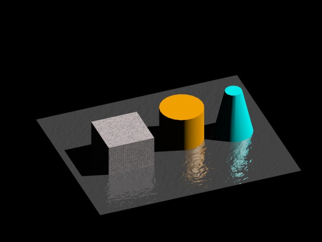
- Rendering the
view indicates some less than fully satisfactory representation of
water.
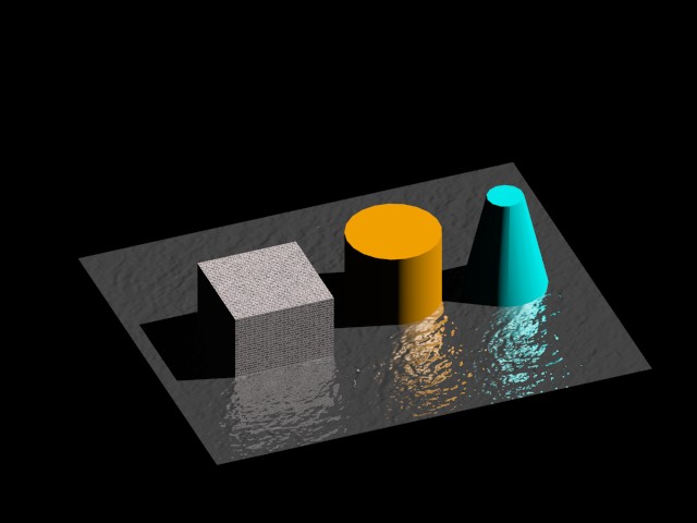
- Increasing the
intensity of the bump map, as was as "Specular", and
"Reflect" produces a potentially more satisfying result.
- Note that
continuous adjustment of values by trial an error may be necessary to
arrive at the most desired results. We will later explore the technique
of "reflection mapping" that may also help to improve upon the
representation of the water.
8. MODIFY
PROCEDURE TEXTURE MAP & CREATE YOUR OWN
In step 7 you had
acquired the procdure texture map via the palette> open sequence:
(the palette is
located in system folder such as C:\Documents and settings\All
Users\Application
Data\Bentley\Workspace\System\Materials).
- You might
continue to "save as" the palette as myproc.pal in your local c: drive
(or local t: drive if using a School of Architecture computer).
- This includes
your copy of the brick (Flemish bond) and renaming it (e.g.,
"myflemishbond).
- Note that have
renamed the material andthe palette file so as to conflict with the
system version of this file.
9. SAVING THE
MATERIALS TABLE AND PALETTE FILES (UPDATED INSTRUCTIONS)
Material tables and
palette files are saved internally to the
CAD file. However, if you want to reuse the table and palette for a new
file, especially one modified andre-imported from Rhino, there are two strategies:
9. a. Save The Material
and Palette File through the Assign Material Dialog Box and the Materials Editor
This method preserves the
Materials Table and also Palette File Assignments to Materials. In this approach, you need to have both the original and more recent update file available, and you need to follow the entire sequence on the same computer. If you working from your laptap, you can do this procedure without having to have both the older and newer files available at the same time.
Starting with the older file saved to the dgn (Microstation format), once
you've concluded making the materials table and associated palette file:
EXPORT FROM INITIAL FILE
- go to the material
editor,and select the menu item sequence Palette\local materials\copy to
library
- next, select the palette you wish to save externally to the dgn file, go to the menu item
sequence Palette "saveas" and save the palette file to same folder as the
dgn file
- next, go to the
"Visualization Task" on the left-hand side of the view window and select the "Apply
Material" Icon
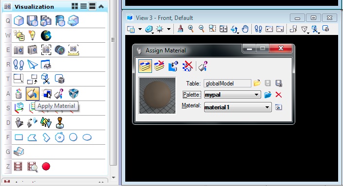
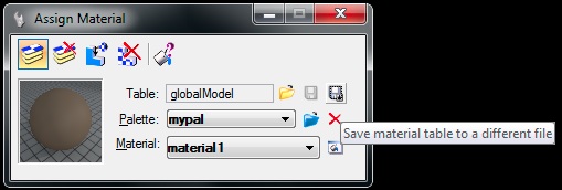
- in the dialog box that
follows, go to last icon to the right of the word"Table" and select it to write the table
and associated palette files to an external file:
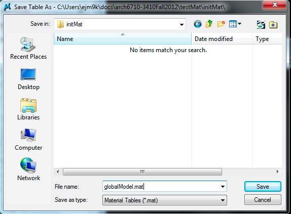
- the "save as" dialog box appears as follows:
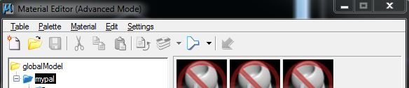
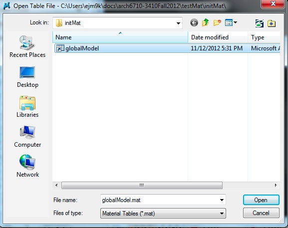
IMPORT INTO UPDATE FILE
- Lets assume you modify the original Rhino file and save it to a new
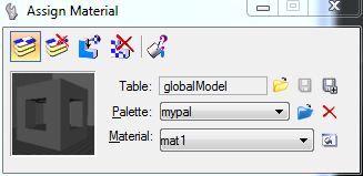
microstation file. Now, go to the"Assign Material" dialog
box, and choose the yellow-folder icon to open
the externally saved material table:
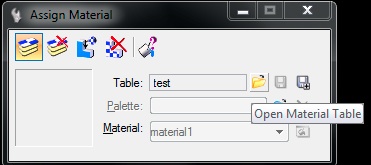
- in the file open dialog
box that folllows, choose the material table (e.g., "globalModel.mat")
saved earlier:
- next, within the same assign
material dialog box, choose the blue folder icon adjacent to the world "Palette" and load up the palette files saved earlier on at a time
- returning to the
Material Editor, note that the the prior table, associated palette file
and material assignments are all restored
9. b. Save The Material
Table andPalette File Through the Material Table Dialog Box. This is an
older method.
Optionally, save the
Material Table and Palette to external files if you want to re-use
them in other CAD models. Using this method you need to redo the
assignments of specific materials to parts of the 3D model.
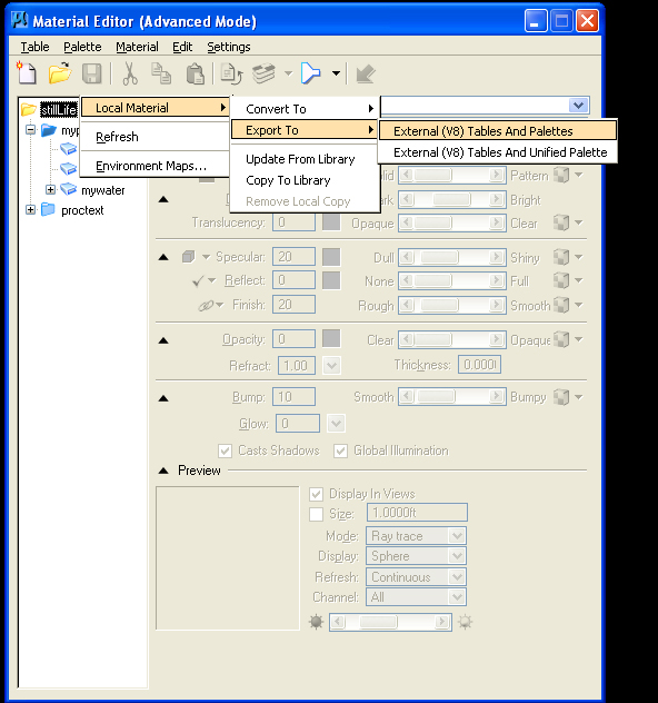
- In the new
palette, right-click on the table name "stillLife"
- Select the Local
Material/Export option.
- Export to either
a single material table and multiple palettes, or to a single
material table and unified palette file.