1. Hello World and Simple VB Scripts
In some circumstances it may be more effective to use a Visual Basic Script (VB Script) component in conjunction with other Grasshopper components. We begin with a few simple VB scripts. These first scripts are for introductory purposes and don't necessarily offer an advantage over other Grasshopper components. We will then move onto VB Scripts which may offer advantages over other Grasshopper options.
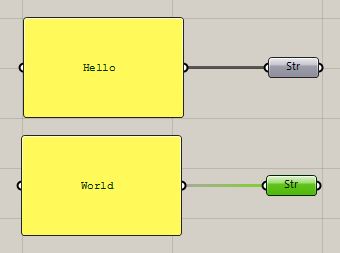
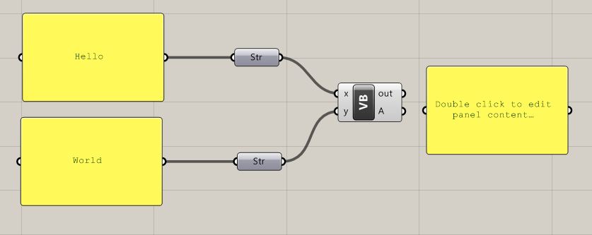
First, we demonstrate a script that outputs the text string "Hello World!". This follows a tradition of introducing programming languages with a "Hello World!" example to establish a basic understanding . Launch Rhino and Grasshopper, and load the file helloworld.gh. The file shows two VB scripts, one that echoes back the text string "Hello World!" and a second that returns the sum of two numbers.
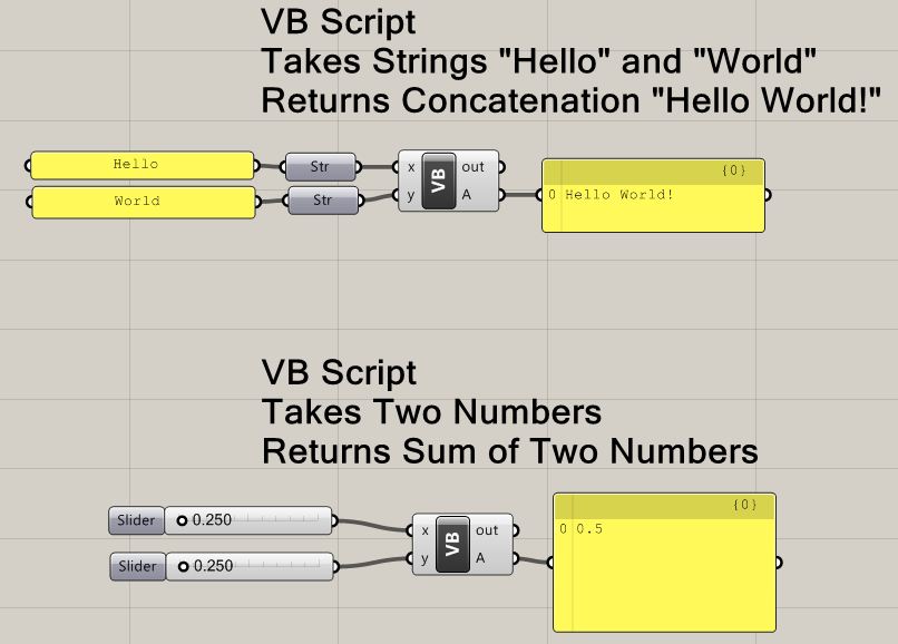
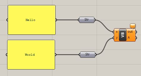
Note that the input text strings "Hello" and "World" are connected to two "Str" (string) components. The two "Str" components are in turn connected to the VB Script input parameters "x" and "y". The VB Script in turn returns the parameter "A", which is the text string "Hello World!".
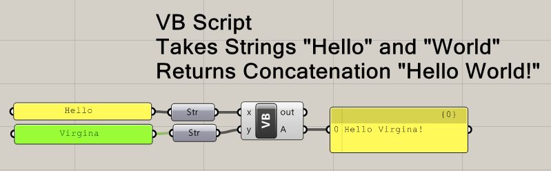
If you modify either of the input text strings, then the output text string is modified accordingly, such as replacing the text string "World" with the text string "Virginia" in the example below:
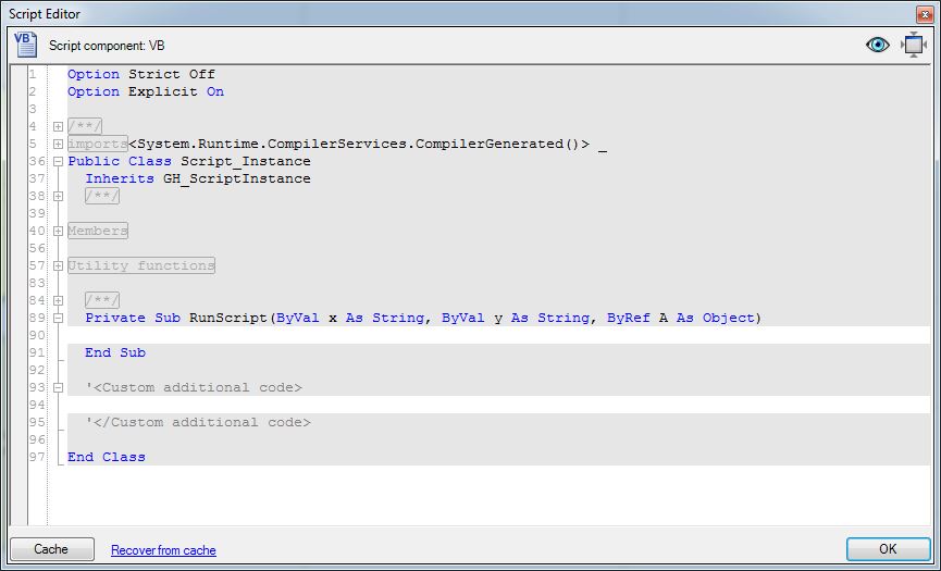
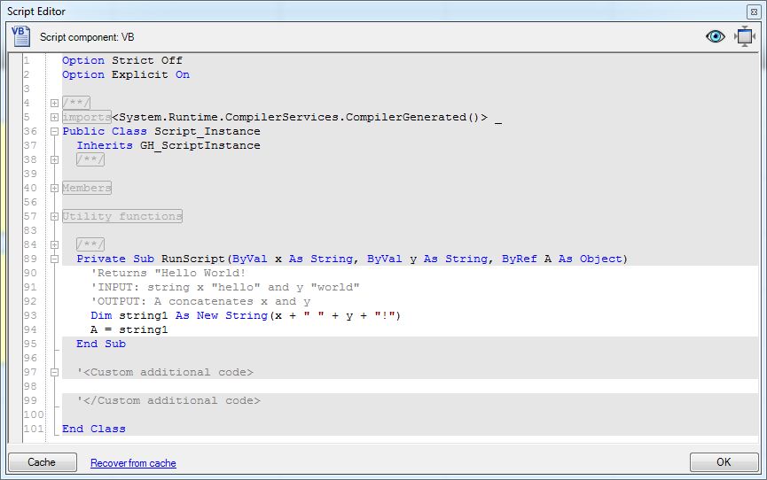
To see the VB Script in detail, double click on "VB" icon in the Grasshopper window to launch the script editor.
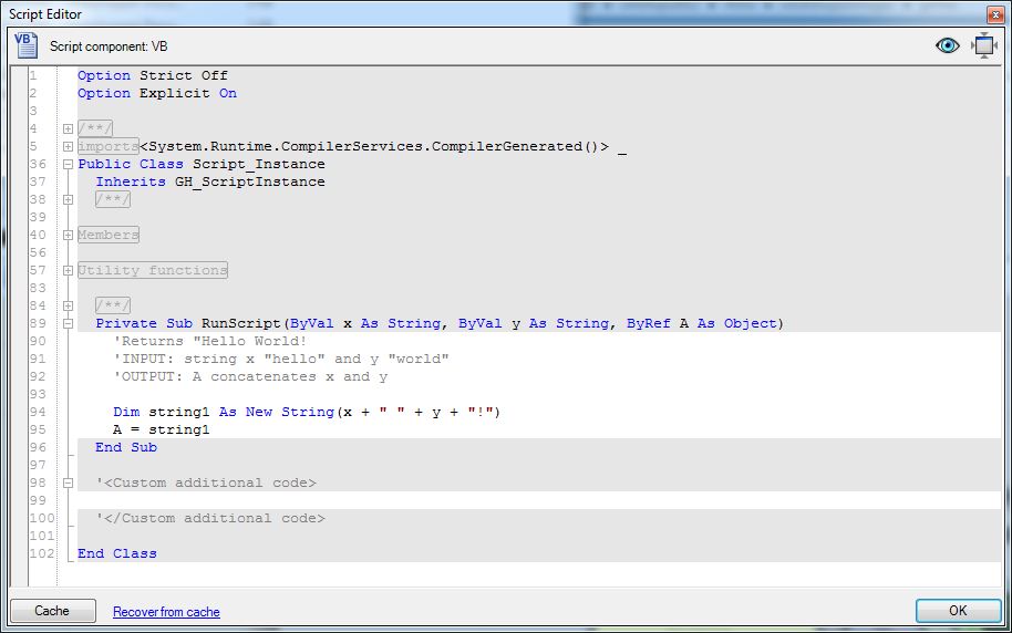
Note that the two input arguments "x" and "y" are passed into the VB script component "ByVal" and as "As String" type variables. The "String" designation means that both "x" and "y" are a text expression of alphanumeric characters. The "ByVal" designation means that any change to the value of the variable (such as "x" or "y") inside the VB Script component is limited in scope to be internal to the script function. However, the modification to the value of the variable internal to script function doesn't change its value outside the script. Thus if we added the line to the above script x = "virginia film festival". The value of x outside of the script would be unchanged from x = "World".
Note also that the one
output variable "A" is returned from the script "ByRef". The
"ByRef" designation means that any change to the value of the
variable "A internal to the script function concurrently modifies
its value outside
of the script function. Thus, since "A" is returned from the VB
Script, the
value of A = string1 (i.e., "Hello World!") can be input in the
yellow panel shown above.
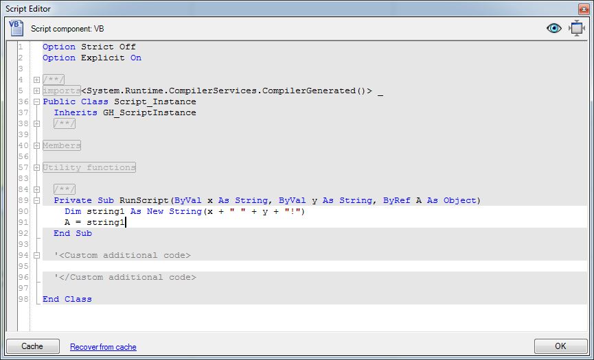
Lets break down the statements on lines 94 and 95 in the Script Editor above.
The first statement on line 94 declares a new string variable "string1" by joining together 1. the value of the string x, 2. a blank space " ", 3. the string y, and 4. the exclamation point "!". Note that the use of the "+" symbol is used to add together (concatenate) the larger string from the the strings "Hello", " ", World, "!", similar to how one might add several numbers together.
Dim string1 As New String(x + " " + y + "!")
Within the VB Script component, the second statement on line 95 assigns the concatenated string to the output variable "A".
A = string1
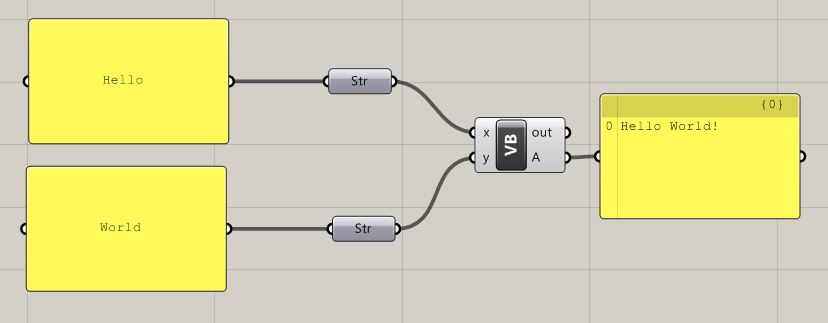
The output variable "A" is in turn directed to the input port of the yellow panel that displays the result "Hello World!".
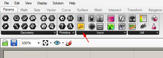
Now we will reconstruct the script from scratch. Go to File/New Script. Go to the "Params" tab and in the "Input" area, select the yellow panel.
Drag two yellow panels with the left-mouse button into the Grasshopper view window.
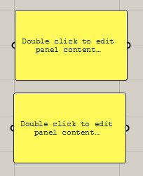
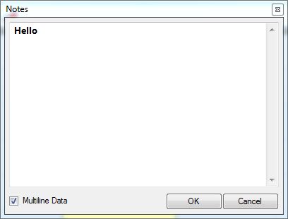
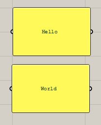
Double click on each panel, and edit the text string to become "Hello" on on panel and to become "World" pn the other panel.
The result is that the panels should transform as follows.
Continuing with the "Params" tab, go to the "Primitive" area and select the string component.
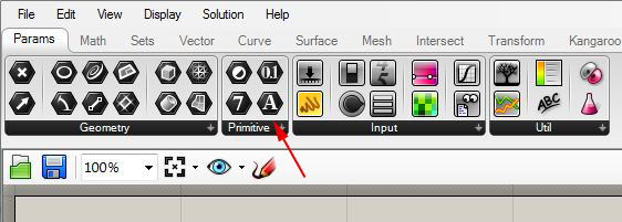
Drag two string components with the left-mouse button into the Grasshopper view window, and connect their input ports to the output ports of the two yellow panels.
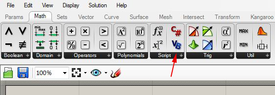
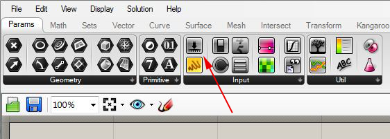
Now go the the "Math" tab and in the "Input" area, select the yellow panel "VB".
Drag on VB component with the left-mouse button into the Grasshopper view window and connect its input ports to the output ports of the two string components.
Zoom into the VB component , right-click on the letter "x", go the the "Type hint" item, and change the type to "String". Do the same for the letter "y" variable.
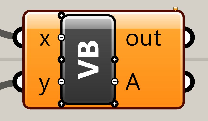
Now, double-click on the VB symbol in order to open the VB editor. Note that the input variables "x" and "y" are declared in the function as type "String" variables.
Dim string1 As New String(x + " " + y + "!")
A = string1
Select the "OK" button on the lower right hand corner of the Script Editor to conclude editing the script. Go back to the "Params" tab and to "Input" area, select the yellow panel , add it to the right of the VB script within the Grasshopper view window.
Connect the output port "A" of the VB script to the yellow panel to obtain the final result of the VB script.
Note that it is generally quite useful to document the purpose, input and output functions of the VB script with comment lines. Comment lines are not executed and are preceded by a single quote symbol " ' " (e.g., 'This is a comment line). For example, double-click on the VB component, and add the comment lines just below the line "Private Sub RunScript(ByVal x As String, ByVal y As String, ByRef A As Object)"
'Returns "Hello World!
'INPUT: string x "hello" and y "world"
'OUTPUT: A concatenates x and y
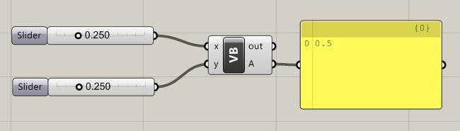
The VB script to construct two numbers is constructed in a similar way. Go to the "Params" tab and from the "Input" and a number slider.
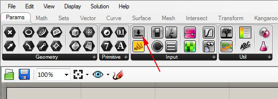
Drag two number sliders into the Grasshopper view window. Now, similar to the "Hello World" example, go to the Math "Tab" and from the "Script" area drag VB component with the left-mouse button into the Grasshopper view window and connect its input ports to the output ports of the two number slider components.
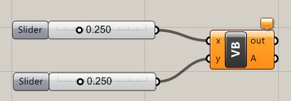
Zoom into the VB component , right-click on the letter "x", go the the "Type hint" item, and change the type to "Double". Do the same for the letter "y" variable. Double click on the VB Symbol in order to open the VB Editor. Note that the input variables "x" and "y" are declared in the function as type "Double".
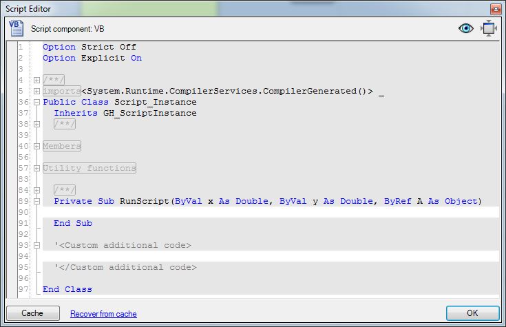
The following comment lines and expressions are now added to complete the VB script and return the result in the variable A.
'Adds Two Numbers
'INPUT: numbers x and y
'OUT: sum of x and y
A = x + y

Finally, select the "OK" button on the lower right hand corner of the Script Editor to conclude editing the script. Go back to the "Params" tab and to "Input" area, select the yellow panel , add it to the right of the VB script within the Grasshopper view window. Connect the output port "A" of the VB script to the yellow panel to obtain the final result of the VB script.
2. Scripts to Draw a Few Graphic Primitives
Within the previous set of Grasshopper workshop notes (workshop 9), we covered how to generate a line from two points. Here we perform the same task by using a VB script to produce a grasshopper file makeSimpleLine.gh.
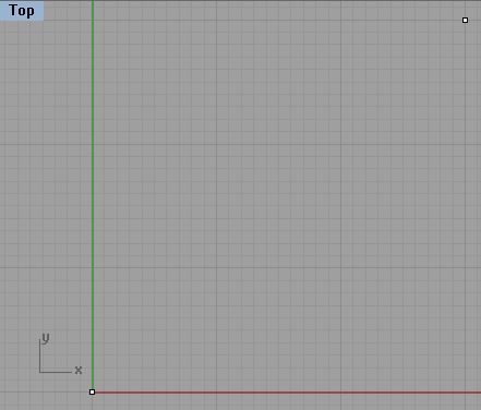
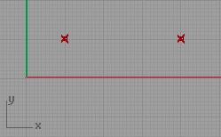
Initiate the script within Rhino by creating two points in the x, y ground plane.
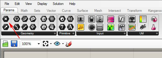
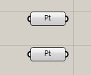
Within Grasshopper, go to the "Params" tab and within the "Geometry" area, select and drag two point icons into the work area.
Right-click on each of the two points and use the "set on point" option to connect them to the points created on the x, y plane.
Next, similarly to "Hello World" example above, go the "Math" tab and within the "Script" area drag a "VB" component into the Grasshopper View window.
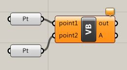
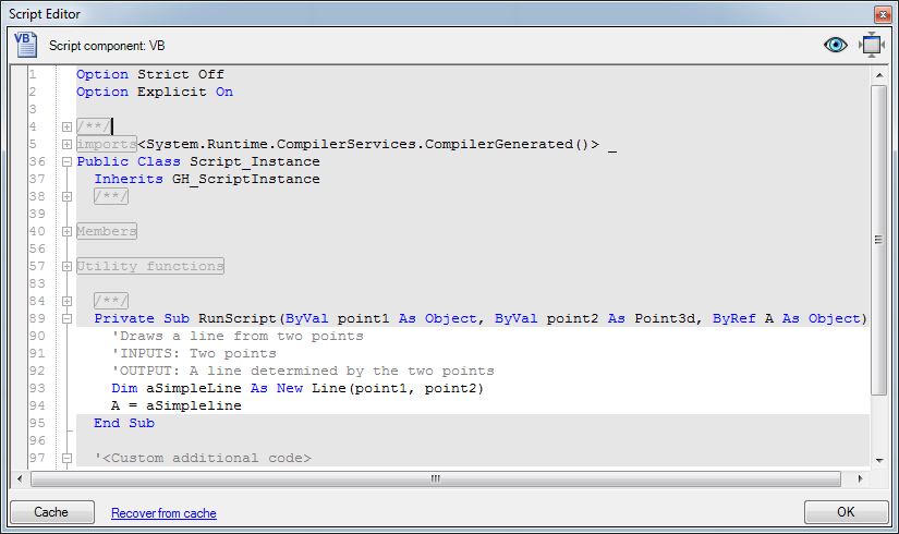
Double-click on "VB" of the VB scripting component, to go to the script editor, and add the following expressions:
Add the following
comment lines at the beginning of the script:
'Draws a
line from two points
'INPUTS: Two points
'OUTPUT: A line determined by the two points
Add the following statements after the comment lines:
Dim
aSimpleLine
As New Line(point1, point2)
A = aSimpleLine
Within the script editor we see the following result:
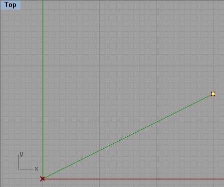
This completes the script and resulting line should now appear inside Rhino.

Move either of the two points and the line is modified accordingly.
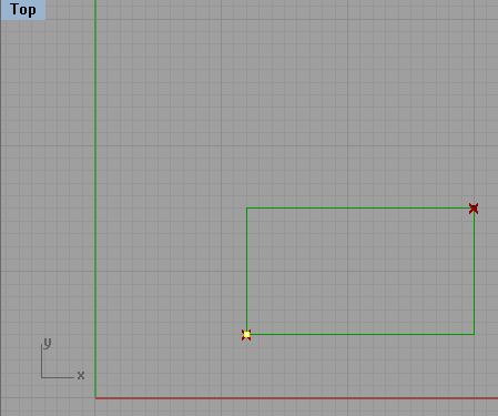
The same script can be modified to draw a rectangle, makeSimpleRectangle.gh, from the initial end points.
First, note that we can extract the coordinates x1, y1, z1 from point1 and the coordinate x2, y2, and z2 from point2. We can combine the two sets of coordinate to get the four points cornerPt1, cornerPt2, cornerPt3 and cornerPt4, that detemine the rectangle. Assuming that both point1 and point2 are in the x-y plane, also note that z1 = z2. That is, we have the following way to establish the values of the four corner points.
cornerPt1 - based
upon x1, y1, z1
cornerPt2 - based upon x2, y1, z1
cornerPt3 - based upon x2, y2, z1
cornerPt4 - based upon x1, y2, z1.
With this in mind, we can edit the VB script as indicated below to get a rectangle. Note that comment lines added to the script describe what is achieved by each step.
'Draws a
rectangle from two points
'INPUTS: Two points
'OUTPUT: A polyline (rectangle) determined by the two
points
'Create a point list array to hold
the corner points
Dim cornerPts As New Point3dList
'Create the corner points from the
x, y, and z coordinates of
point1 and point2
Dim cornerPt1 As New Point3d(point1.X, point1.Y, point1.Z)
Dim cornerPt2 As New Point3d(point2.X, point1.Y, point1.Z)
Dim cornerPt3 As New Point3d(point2.X, point2.Y, point2.Z)
Dim cornerPt4 As New Point3d(point1.X, point2.Y, point1.Z)
'Add the corner points to the
point list
cornerPts.Add(cornerPt1)
cornerPts.Add(cornerPt2)
cornerPts.Add(cornerPt3)
cornerPts.Add(cornerPt4)
cornerPts.Add(cornerPt1)
'Create the polyline from the
list of points
Dim aPolygonLine As New Polyline(cornerPts)
'Return the polyline
from the VB script
A = aPolygonLine
The script editor is now modified as follows.

The script as now completed draws a rectangle. Note that moving the lower left corner point from within Rhino dynamically redraws the rectangle.
Looking at this script in greater detail, observe that we have introduced a point list array Point3dList with the statement
Dim cornerPts As New Point3dList
Points are added to this list in the order in which they were created with the statement
cornerPts.Add(cornerPt1)
This list has a zero based indexing system such that:
cornerPts(0) =
cornerPt1 {the lower-left point of the rectangle
cornerPts(1) = cornerPt2 {the lower-right point of the rectangle
cornerPts(2) = cornerPt3 {the upper-right point of the rectangle
cornerPts(3) = cornerPt4 {the upper-left point of the rectangle
cornerPts(4) = cornerPt1 {the lower-left point of the rectangle
We add the
lower-left point to both the beginning and the end of the list to
ensure that we get a closed polyline..
Note too that we introduced a polyline object variable with the
statement
Dim aPolygonLIne As New Polyline(cornerPts)
The polyline object variable is thus initialized with the listing of points.
3. Script That Uses Iteration to Express Recurring Relationship With An Exit ConditionTo draw a series of inwardly rotating polylines makeInwardlyTurningRectangle.gh from the outer rectangle, we need to repeat a similar operation a specified number of times.
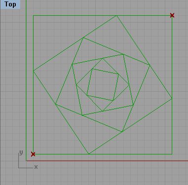
Note that in the figure above, each inner polyline is calculated from point that is 40% along along each of the four sides of the next outer polyline. In the VB script used to generate this figure, a technique referred to as iteration is used to repeat the same process a given number of times. A number of such iterative expressions exist within the VB scripting language. Within the current example, we use a "For" expression that for some integer " i" steps in value from 1 to the number of times we want to repeat the procedure :
For i = 1 to numberTimes
Calculate four points of each new polyline
Create a new polyline from the four points
Add the polyline to a list of polylines
next
Note that the "For" expression is concluded with a "next" expression to indicate where the iteration is repeated until completed.
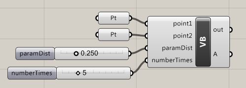
First, lets begin by adding to new parameters to the Grasshopper Script from Part 3. Go to the "Params" tab and in the "Input" area add two numerical sliders to the Grasshopper view window.
Double-click on the word "slider" and rename the numerical sliders paramDist and numberTimes. The paramDist slider by default ranges in value from 0.0 to 1.0, which we can use to represent 0% to 100% of the distance along any side of the last outer polygon. Adjust the numberTimes slider so that it ranges in value from 0 to 20, and adjust the type to"N" (integer numbers).
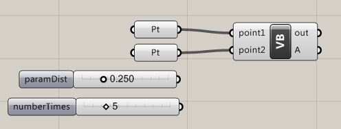
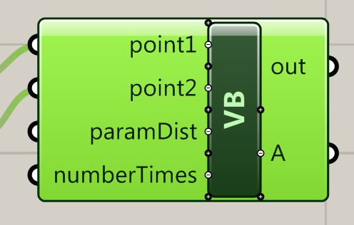
Zoom up on the VB script symbol until "+" symbols appear below the input variables "point1" and "point2".
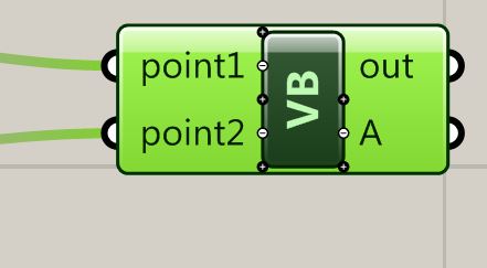
Select the "+" symbol below "point2" to add a variable "paramDist". Change the default name of "x" to "paramDist" and change the Type hint option to "Double". Similarly, select the "+" symbol below "paramDist". Change the default name of "x" to "numTimes" and change the Type hint option to "Integer".
Next, connect the output ports of the two numerical sliders to the new
input variables of the VB script.
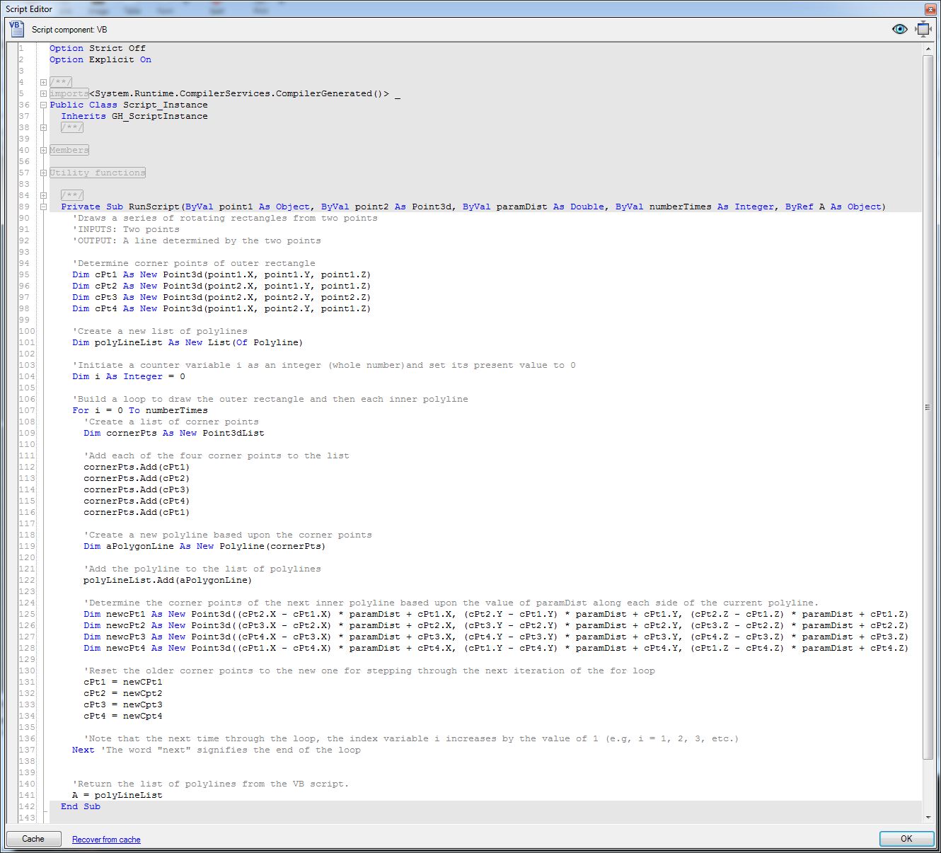
Now, to create the series of rectangles we edit the VB script to incorporate the following text. Comment lines preced by a "': describe what each step of the VB script does.
Private Sub
RunScript(ByVal point1 As Object, ByVal point2 As Point3d, ByVal
paramDist As Double, ByVal numberTimes As Integer, ByRef A As Object)
'Draws a series of rotating rectangles from two
points
'INPUTS: Two points
'OUTPUT: A line determined by the two points
'Determine
corner points of outer rectangle
Dim cPt1 As New Point3d(point1.X, point1.Y, point1.Z)
Dim cPt2 As New Point3d(point2.X, point1.Y, point1.Z)
Dim cPt3 As New Point3d(point2.X, point2.Y, point2.Z)
Dim cPt4 As New Point3d(point1.X, point2.Y, point1.Z)
'Create a new
list of polylines
Dim polyLineList As New List(Of Polyline)
'Initiate a
counter variable i as an integer (whole
number)and set its present value to 0
Dim i As Integer = 0
'Build a loop
to draw the outer rectangle and then
to draw each inner polyline
For i = 0 To numberTimes
'Create a list of corner points
Dim cornerPts As New Point3dList
'Add
each of the four corner points to
the list
cornerPts.Add(cPt1)
cornerPts.Add(cPt2)
cornerPts.Add(cPt3)
cornerPts.Add(cPt4)
cornerPts.Add(cPt1)
'Create a new polyline based upon the
corner points
Dim aPolygonLine As New
Polyline(cornerPts)
'Add
the polyline to the list of
polylines
polyLineList.Add(aPolygonLine)
'Determine
the corner points of the next
inner polyline based upon the value of paramDist along each side of the
current polyline.
Dim newcPt1 As New Point3d((cPt2.X -
cPt1.X) * paramDist + cPt1.X, (cPt2.Y - cPt1.Y) * paramDist + cPt1.Y,
(cPt2.Z - cPt1.Z) * paramDist + cPt1.Z)
Dim newcPt2 As New Point3d((cPt3.X -
cPt2.X) * paramDist + cPt2.X, (cPt3.Y - cPt2.Y) * paramDist + cPt2.Y,
(cPt3.Z - cPt2.Z) * paramDist + cPt2.Z)
Dim newcPt3 As New Point3d((cPt4.X -
cPt3.X) * paramDist + cPt3.X, (cPt4.Y - cPt3.Y) * paramDist + cPt3.Y,
(cPt4.Z - cPt3.Z) * paramDist + cPt3.Z)
Dim newcPt4 As New Point3d((cPt1.X -
cPt4.X) * paramDist + cPt4.X, (cPt1.Y - cPt4.Y) * paramDist + cPt4.Y,
(cPt1.Z - cPt4.Z) * paramDist + cPt4.Z)
'Reset the older corner points to the
new one for stepping through the next iteration of the for loop
cPt1 = newCPt1
cPt2 = newCpt2
cPt3 = newCpt3
cPt4 = newCpt4
'Note that the next time through the
loop, the index variable i increases by the value of 1 (e.g, i = 1, 2,
3, etc.)
Next 'The word
"next" signifies the end of the loop
'Return the list
of polylines from the VB script.
A = polyLineList
End Sub
The Script Editor now appears as follows.
3.
Script That Uses Iteration to Generate A Helix
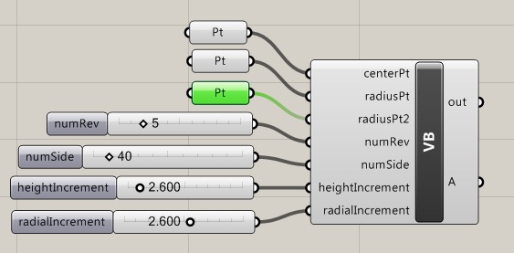
To draw a series of inwardly rotating polylines form the outer rectangle, we needed to repeat a similar operation a specified number of times. Similar to the rotating figure above, a helix, such as determined by, adjustableHelix.gh, can also be described by a loop. The vertices that are used to define the spiral are also created in a repeated operation for a specified number of times. Using tools described previously, initiate the helix by placing two point parameters with a Grasshopper window, and by also adding four numerical slider parameters. One point will be used to identify the center of the spiral. The second point will be used to define the radius. The following sliders should have the following value types and ranges:
| Name of Slider | Description | Type | Min Value | Max Value |
| numRev | number of revolutions in the spiral | Integer (N) | 1 | 25 |
| numSide | number of sides in each revolution of the sprial | Integer (N) | 3 | 360 |
| heightIncrement | height increment in each revolution of the spiral | Floating Point (R) | 0 | 25 |
| radiaIncrement | radius increment in each revolution of the sprial | Floating Poing(R) | -25 | 25 |
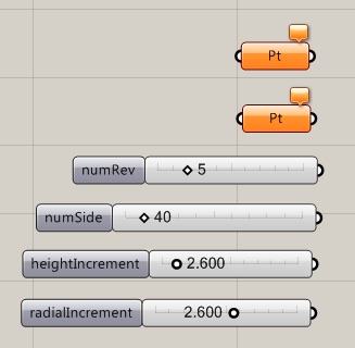
Next, create two points in Rhino and connect them to the point input parameters, as done in previous examples. The two points will serve as the center point and radial point of the sprial.
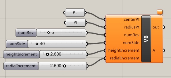
Now, add a VB script component to the Grasshopper View window and add the following input variables and types (use the Type hint feature as done in earlier examples):
| Name of Variable | Description | Type hint |
| centerPt | center point of helix | Point3d |
| radiusPt | radial point of helix | Point3d |
| numRev | number of revolutions in the spiral | Double |
| numSide | number of sides in each revolution of the sprial | Double |
| heightIncrement | height increment in each revolution of the spiral | Double |
| radiaIncrement | radius increment in each revolution of the sprial | Double |
Note that the sliders for numRev and numSide ares specified at Integers, but that the input variables numRev and numSide are specified as Double (i.e. floating point numbers). Thus the values are converted from integers to floating point numbers when connected to the VB script. The integer designation for the sliders ensures that only whole numbers are selected. This conversion to floating point numbers ensures that floating point accuracy is maintained in the VB script where needed in some operations.
Finally, double-click on the VB script and add the following expression into the script editor. Note the the first line "Private Sub Runscript ... "(etc.) is already given.
Private Sub
RunScript(ByVal centerPt As Point3d, ByVal radiusPt As Point3d, ByVal
numRev As Double, ByVal numSide As Double, ByVal heightIncrement As
Double, ByVal radialIncrement As Object, ByRef A As Object)
'Draws a helix
'INPUTS: centerPt and radiusPt of helix
'numRev = number of revolutions in helix
'numSide = number of sides per revolution
'heightIncrement = height increment per revolution
'radialIncrement = radius increment per revolution
'OUTPUTS: A = polyline approximation of helix curve.
'Declare
variables for spiral point list and radius
Dim ptList As New List(Of Point3d)
Dim radius As Double
'Declare vector
from center point to radius point, and set radius to value of vector
length
Dim radialVector As New Vector3d(RadiusPt.X - CenterPt.X, RadiusPt.Y -
CenterPt.Y, RadiusPt.Z - CenterPt.Z)
radius = radialVector.Length
'Declare
variable to hold incremental values of rotation angle, height and
radius for each point in the spiral
Dim angleIncrement As Double = 360.0 / numSide
Dim ptHeightIncrement As Double = heightIncrement / numSide
Dim ptRadialIncrement As Double = radialIncrement / numSide
'Declare
variable to hold the initial values for the angle, height and radius
Dim curAngle As Double = 0
Dim curHeight As Double = 0
Dim curRadius As Double = radius
'Loop to
generate points in the spiral
For i As Integer = 1 To numRev * numSide
'Determine x, y, and z coordinates of each point
Dim x As Double = math.Cos(math.PI / 180.0 * curAngle) * curRadius
Dim y As Double = math.Sin(math.PI / 180.0 * curAngle) * curRadius
Dim z As Double = curHeight
Dim curPt As New Point3d(CenterPt.X + x, CenterPt.Y + y, CenterPt.Z + z)
'Add each
successive point to the point list
ptList.Add(curPt)
'Advance the
values of the current angle, current height and current radius for the
next point in the spiral
curAngle = curAngle + angleIncrement
curHeight = curHeight + ptHeightIncrement
curRadius = curRadius + ptRadialIncrement
Next' end of loop
'Determine a
polyline from the point list
Dim pLine As New Polyline(ptList)
'Return the
polyline to Rhino
A = pLine
End Sub
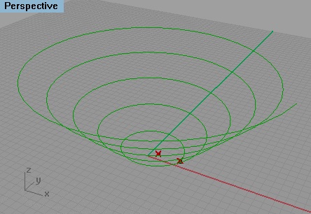
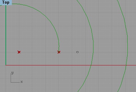
Select the "OK" button in the editor and the Grasshopper file will produce the helix as depicted in the following image.
4.
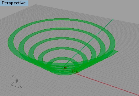
Script That Uses Iteration to Generate A Ramp
The helix script can be enhanced to become todraw two spirals that form a ramp, as illustrated by the Grasshopper file adjustableRamp.gh.The essential strategy for looping through vertices is the same. Begin by adding a radial point within Rhino to determine the location of the second helix.
Next, within Grasshopper add a new point input parameter radialPt2 and
connect it to the recently added radial point, and a corresponding
Point3D variable "radiusPt2" to the VB script.
Within the VB script, we now double up on the points so as to produce two spirals rather than one spiral. Furthermore, rather than use the points to form a polyline as in the previous example of the helix, we use them to form two bspline curves. Next, the bspline curves are used to generate a ruled surface. Whereas polylines can not be used to generate a ruled surface, the bspline curves can be used to generate one.
The VB Script is
thus modified as follows. See the comment lines below in grey (e.g., 'Declare variables) for details:
Private Sub RunScript(ByVal centerPt As Point3d,
ByVal radiusPt As Point3d, ByVal radiusPt2 As Point3d, ByVal numRev As
Double, ByVal numSide As Double, ByVal heightIncrement As Double, ByVal
radialIncrement As Object, ByRef A As Object)
'Draws a helix ranp
'INPUTS: centerPt and radiusPt of helix
'numRev = number of revolutions in helix
'numSide = number of sides per revolution
'heightIncrement = height increment per revolution
'radialIncrement = radius increment per revolution
'OUTPUTS: A =ramp based upon helix curves
'Declare
variables for spiral point lists and radii
Dim ptList As New List(Of Point3d)
Dim ptList2 As New List(Of Point3d)
Dim radius As Double
Dim radius2 As Double
'Declare vectors
from center point to radius point, and set radius to value of vector
length
Dim radialVector As New Vector3d(RadiusPt.X - CenterPt.X, RadiusPt.Y -
CenterPt.Y, RadiusPt.Z - CenterPt.Z)
radius = radialVector.Length
Dim radialVector2 As New Vector3d(RadiusPt2.X - CenterPt.X, RadiusPt2.Y
- CenterPt.Y, RadiusPt2.Z - CenterPt.Z)
radius2 = radialVector2.Length
'Declare
variables to hold incremental values of rotation angle, height and
radius for each point in the spiral
Dim angleIncrement As Double = 360.0 / numSide
Dim ptHeightIncrement As Double = heightIncrement / numSide
Dim ptRadialIncrement As Double = radialIncrement / numSide
'Declare
variables to hold the initial values for the angle, height and radius
Dim curAngle As Double = 0
Dim curHeight As Double = 0
Dim curRadius As Double = radius
Dim curRadius2 As Double = radius2
'Loop to
generate points in the two spirals
For i As Integer = 1 To numRev * numSide
'Determine x, y, and z coordinates of each point
Dim x As Double = math.Cos(math.PI / 180.0 * curAngle) *
curRadius
Dim y As Double = math.Sin(math.PI / 180.0 * curAngle) *
curRadius
Dim z As Double = curHeight
Dim curPt As New Point3d(CenterPt.X + x, CenterPt.Y + y,
CenterPt.Z + z)
Dim x2 As Double = math.Cos(math.PI / 180.0 * curAngle) *
curRadius2
Dim y2 As Double = math.Sin(math.PI / 180.0 * curAngle) *
curRadius2
Dim z2 As Double = curHeight
Dim curPt2 As New Point3d(CenterPt.X + x2, CenterPt.Y +
y2, CenterPt.Z + z2)
'Add each
successive point to the two point lists
ptList.Add(curPt)
ptList2.Add(curPt2)
'Advance the
values of the current angle, current height and current radius for the
next point in each of the point lists
curAngle = curAngle + angleIncrement
curHeight = curHeight + ptHeightIncrement
curRadius = curRadius + ptRadialIncrement
curRadius2 = curRadius2 + ptRadialIncrement
'End of loop
Next
'Create inner and outer curves (not
polylines) based upon the ptlists
Dim pCurve1 As New NurbsCurve(1, numRev * numSide)
pCurve1 = NurbsCurve.Create(False, 1, ptList)
Dim pCurve2 As New NurbsCurve(1, numRev * numSide)
pCurve2 = NurbsCurve.Create(False, 1, ptList2)
'Build ruled
surface from the two curves
Dim rampSurf As NurbsSurface
rampSurf = NurbsSurface.CreateRuledSurface(pCurve1, pCurve2)
'Return ruled
surface to be displayed in Rhino
A = rampSurf
End Sub
Note that we used some new statements to determine a surface.
'Build ruled surface
from the two curves
Dim rampSurf As NurbsSurface
rampSurf = NurbsSurface.CreateRuledSurface(pCurve1, pCurve2)
In particular we used a function library NurbsSurface.CreateRuledSurface. A number of functions have been created for Grasshopper to generate geometry and handle other requirements. This is currently under development. The documentation is incomplete. The current listing of functions and related examples can be found in the web site:
http://www.rhino3d.com/5/rhinocommon/
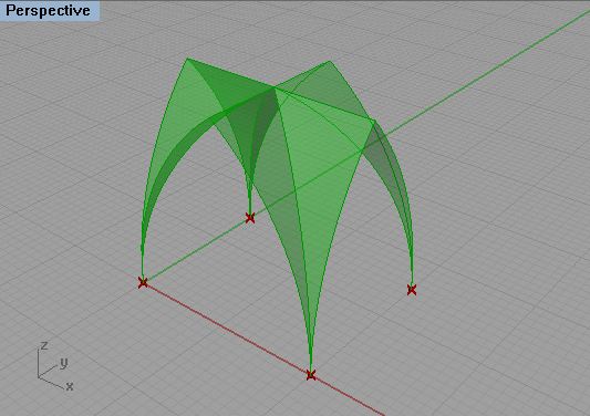
5. VB Scripts That Include Sub Functions
The previous examples rely upon VB scripts that contain one main function each. However, in some circumstances, the logic of a VB script may be more concisely organized into a main top level function to broadly outline the process needed and other sub functions to perform more specific tasks. This is the case of a script, makeQuadripartiteVault.gh, that generates a quadripartite vault from four corner points on the x-y ground plane.
The basic components of the script are the same as what was used in previous examples for this set of workshop notes. For "pt" components are linked to the four points on the ground in counter-clockwise order. A numerical slider that ranges in value from -5 to 5 is used to determine the height difference if any between the central crossing arches and the side archest of the vault. The VB script accepts the four ground points and height difference number as inputs. It returns the vault surfaces as output.
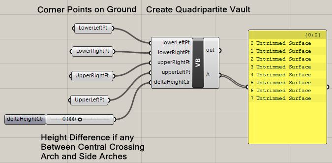
Note that on the right-hand side of the Grasshopper window, a yellow panel is used to echo back the output of the function. To place such as yellow panel inside the Grasshopper window, go to the "Params Tab"and the "Input Area", select a yellow panel and connect to the output of the VB script similar to the VB function.
Within the VB script the main upper level function describes the meta logic of what is done at an abstract level. The sub functions perform more of the explicit tasks called upon by the main upper level function. In this example, the construction of the quadripartite vault follows the upper level seven step sequence of:
1. Start with the
four corner points on the ground in counter-clockwise order
(lower-left, lower-right, upper-right, upper-left)
2. Determine the center of the vault on the ground
3. Determine the center arches apex point
4. Determine the side arches apex points
5. Determine the central crossing arches
6. Determine the side crossing arches
7. Loft vault surfaces between corresponding arches
Private Sub RunScript(ByVal lowerLeftPt As Point3d, ByVal lowerRightPt As Point3d, ByVal upperRightPt As Point3d, ByVal upperLeftPt As Point3d, ByVal deltaHeightCtr As Double, ByRef A As Object)
'Creates A Quadripartite Vault from four points on the the Ground (x-y plane)
'INPUTS: corner points on ground LlowerLeftPt, lowerRightPt, upperRightPt, upperLeftPt
'deltaHeightCtr = difference betweend apex height of central crossing arch and apex of side arches
'OUTPUTS: Surflist = list of eight quadripartite surfaces
'Declare variables for vault center on ground and apex of each arch.
Dim CentroidPt As New Point3d
Dim CtrApexPt As New Point3d
Dim SideApexPt1 As New Point3d
Dim SideApexPt2 As New Point3d
Dim SideApexPt3 As New Point3d
Dim SideApexPt4 As New Point3d
'Declare variables for half crossing arch, lowerleft-to-upperright and lowerright-to-upper left in plan
Dim CrossArc1a As New Rhino.Geometry.Arc
Dim CrossArc1b As New Rhino.Geometry.Arc
Dim CrossArc2a As New Rhino.Geometry.Arc
Dim CrossArc2b As New Rhino.Geometry.Arc
'Declare variables for each half side arch on front, right, back and left elevation
Dim EndArc1a As New Rhino.Geometry.Arc
Dim EndArc1b As New Rhino.Geometry.Arc
Dim EndArc2a As New Rhino.Geometry.Arc
Dim EndArc2b As New Rhino.Geometry.Arc
Dim EndArc3a As New Rhino.Geometry.Arc
Dim EndArc3b As New Rhino.Geometry.Arc
Dim EndArc4a As New Rhino.Geometry.Arc
Dim EndArc4b As New Rhino.Geometry.Arc
'Declare list variable for all surfaces
Dim SurfList As New List(Of Rhino.Geometry.NurbsSurface) 'generate surfaces
'Get the center of the vault on the ground
GetCentroid(lowerLeftPt, lowerRightPt, UpperRightPt, UpperLeftPt, CentroidPt)
'Determine the center arches apex point
GetCtrApexPt(lowerLeftPt, lowerRightPt, UpperRightPt, UpperLeftPt, CentroidPt, CtrApexPt)
'Determine each side arch apex point point
GetSideApexPt(LowerLeftPt, LowerRightPt, CtrApexPt, deltaHeightCtr, SideApexPt1)
GetSideApexPt(LowerRightPt, UpperRightPt, CtrApexPt, deltaHeightCtr, SideApexPt2)
GetSideApexPt(UpperRightPt, UpperLeftPt, CtrApexPt, deltaHeightCtr, SideApexPt3)
GetSideApexPt(UpperLeftPt, LowerLeftPt, CtrApexPt, deltaHeightCtr, SideApexPt4)
'Determine the central crossing arch halves
MakeArcs(LowerLeftPt, CtrApexPt, UpperRightPt, CrossArc1a, CrossArc1b)
MakeArcs(UpperLeftPt, CtrApexPt, LowerRightPt, CrossArc2a, CrossArc2b)
'Determine the side arch halves
MakeArcs(LowerLeftPt, SideApexPt1, LowerRightPt, EndArc1a, EndArc1b)
MakeArcs(LowerRightPt, SideApexPt2, UpperRightPt, EndArc2a, EndArc2b)
MakeArcs(UpperRightPt, SideApexPt3, UpperLeftPt, EndArc3a, EndArc3b)
MakeArcs(UpperLeftPt, SideApexPt4, LowerLeftPt, EndArc4a, EndArc4b)
'Loft surfaces between corresponding side-arch half and central crossing arch-half and add to SurfList
GenVaultSurf(EndArc1a, CrossArc1a, SurfList)
GenVaultSurf(EndArc1b, CrossArc2b, SurfList)
GenVaultSurf(EndArc2a, CrossArc2b, SurfList)
GenVaultSurf(EndArc2b, CrossArc1b, SurfList)
GenVaultSurf(EndArc3a, CrossArc1b, SurfList)
GenVaultSurf(EndArc3b, CrossArc2a, SurfList)
GenVaultSurf(EndArc4a, CrossArc2a, SurfList)
GenVaultSurf(EndArc4b, CrossArc1a, SurfList)
'Return list of vault surfaces
A = SurfList
End Sub
Sub functions are
defined to:
2. GetCtrApexPt: Find the central apex point of the vault.
3. GetSideApexPt: Find the apex point of the side arches relative to the central apex point.
4. MakeArcs: Make arcs for each of the side and central crossing arches
5. GenVaultSurf: Generate vault surfaces between each corresponding side-arch half and central crossing arch half.
Note that each of the sub functions has input data passed to them by means of "ByVal" variables, and returns data by means of "ByRef" variables, similar how the main script function has input data passed to it and returns data.
Sub GetCentroid(ByVal lowerLeftPt As Point3d, ByVal lowerRightPt As Point3d, ByVal upperRightPt As Point3d, ByVal upperLeftPt As Point3d, ByRef CentroidPt As Point3d)
'Determine centroid of four point
Dim x As Double = (lowerLeftPt.X + lowerRightPt.X + upperRightPt.X + upperLeftPt.X) / 4.0
Dim y As Double = (lowerLeftPt.Y + lowerRightPt.Y + upperRightPt.Y + upperLeftPt.Y) / 4.0
Dim Z As Double = (lowerLeftPt.Z + lowerRightPt.Z + upperRightPt.Z + upperLeftPt.Z) / 4.0
CentroidPt.X = x
CentroidPt.Y = y
CentroidPt.Z = z
End Sub
Sub GetCtrApexPt(ByVal lowerLeftPt As Point3d, ByVal lowerRightPt As Point3d, ByVal upperRightPt As Point3d, ByVal upperLeftPt As Point3d, ByVal CentroidPt As Point3d, ByRef CtrApexPt As Point3d)
'Determine central apex point based upon corner point of vault, centroid on ground and CtrApexPt
'Determine vectors between opposite corner points on ground and get their respective lengths
Dim Vect1 As New Vector3d(upperRightPt.X - lowerLeftPt.X, upperRightPt.Y - lowerLeftPt.Y, upperRightPt.Z - lowerLeftPt.Z)
Dim dist1 As Double = Vect1.Length
Dim Vect2 As New Vector3d(lowerRightPt.X - upperRightPt.X, lowerRightPt.Y - upperRightPt.Y, lowerRightPt.Z - upperRightPt.Z)
Dim dist2 As Double = Vect2.Length
'Determine the radius of the central cross arches based upon the average distance between opposite ground corner points
Dim radius As Double = (dist1 + dist2) / 4.0
CtrApexPt.X = CentroidPt.X
CtrApexPt.Y = CentroidPt.Y
CtrApexPt.Z = CentroidPt.X + radius
End Sub
Sub GetSideApexPt(ByVal EndPoint1 As Point3d, ByVal EndPoint2 As Point3d, ByVal CtrApexPt As Point3d, ByVal deltaHeightCtr As Double, ByRef SideApexPt As Point3d)
'Determine side apex point based upon springing points of side arches, central apex point, and height difference if any with central apex point
Dim midPt As New Point3d((EndPoint1.X + EndPoint2.X) / 2.0, (EndPoint1.Y + EndPoint2.Y) / 2.0, (EndPoint1.Z + EndPoint2.Z) / 2.0)
SideApexPt.X = midPt.X
SideApeXPt.Y = midPt.Y
SideApexPt.Z = midPt.Z + CtrApexPt.Z + deltaHeightCtr
End Sub
Sub MakeArcs(ByVal EndPoint1 As Point3d, ByRef ApexPt As Point3d, ByVal EndPoint2 As Point3d, ByRef CrossArcA As Rhino.Geometry.Arc, ByRef CrossArcB As Rhino.Geometry.Arc)
'Determine crossing arch halves CrossArcA and CrossArcB
'Determine up vector tangent to arc at springing point
Dim UpVec As New Vector3d(0, 0, 1)
'Determine arches from endpoints and tangent vector
Dim Arc1 As New Rhino.Geometry.Arc(EndPoint1, UpVec, ApexPt)
Dim Arc2 As New Rhino.Geometry.Arc(EndPoint2, UpVec, ApexPt)
CrossArcA = Arc1
CrossArcB = Arc2
End Sub
Sub GenVaultSurf(ByVal Arc1 As Arc, ByVal Arc2 As Arc, ByRef SurfList As List (Of NurbsSurface))
'Loft surface between corresponding arcs
'Convert arc to arc-curve for compatibility with loft tool
Dim ArcCurve1 As New ArcCurve(Arc1)
Dim ArcCurve2 As New ArcCurve(Arc2)
'Declare vault surface variable
Dim vaultSurf1 As NurbsSurface
'Generate loft surface and add to list of surfaces
vaultSurf1 = NurbsSurface.CreateRuledSurface(ArcCurve1, ArcCurve2)
SurfList.Add(vaultSurf1)
End Sub
The main upper level procedure is somewhat like a general contractor that oversees overall workflow, and indeed can be conceived of without being focused on the details. The sub procedures are like sub-contractors and employed multiple times within the overall process where needed. Given how the geometry has been defined, it is possible to move any of the ground points and determine a more asymmetrical vault.
Or, by entering a series of points, it is possible to replicate the arrangement of a nave, crossing, or ambulatory.

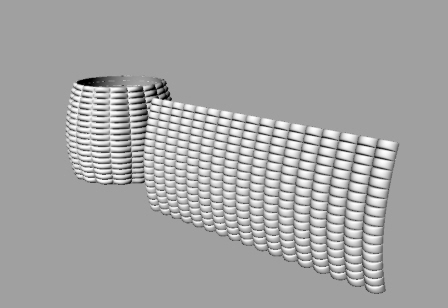
6. VB Scripts Integrated With Other Grasshopper Components
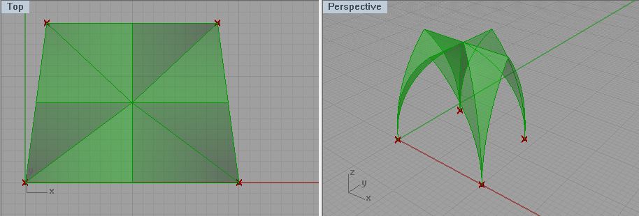
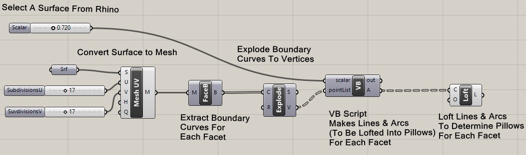
The ramp script can be described relative to a few input parameters and more basic geometrical primitives. Typically applications of scripting respond to more complex circumstances that may involve several stages of converting geometry from one form to another in order to realize a specific solution. For example, the Grasshopper file surftoMeshPillows.gh can be applied a variety of surfaces such as depicted in the Rhino file simpleSaddle.3dm. As illustrated below it converts a simple saddle surface into a mesh surface, and in turn converts the mesh surface into a set of surface pillows. Input variables determine the density of the pillows as well as their relative scale. The VB script geneates a pillow for each facet in the mesh surface.
Without going into detail, which is beyond the scope of these workshop notes, the Grasshopper window has several components.
The initial saddle shape is a modified planar surface with two corner vertices elevated off the x-y plane.
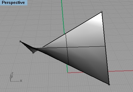
When the Grasshopper file is applied, the saddle shape is converted to a surface array of pillows.
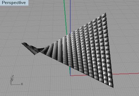
Applying the same Grasshopper file to other surfaces yields similar results.
Some useful sites related to scripting:
http://www.rhino3d.com/5/rhinocommon/
http://quicksilver.be.washington.edu/courses/arch486x/5.Grasshopper/6.Scripting/1.Introduction.html
http://theprovingground.wikidot.com/scripts-mathform
http://community.nus.edu.sg/DigitalDesignMedia/index.php/scripts/grasshopper-script/
http://www.rhino3d.com/5/rhinoscript/vbscript_fundamentals/vbscript_fundamentals.htm
(some parts are outdated, especially related to vbscript)