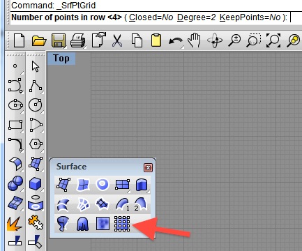
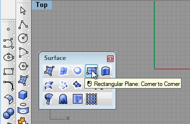
- Select the tool to create planar Surface from four rows of four points from the surfaces palette
COMPUTER
AIDED
ARCHITECTURAL DESIGN
Workshop 5 Notes,
Week of September 30, 2012
Projection With Surface and Solid Editing
PART I: SURFACE EDITING
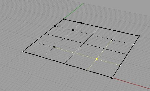
1. Surface Generation with Control Points
- Select the tool to create planar Surface from four rows of four
points from the
surfaces palette
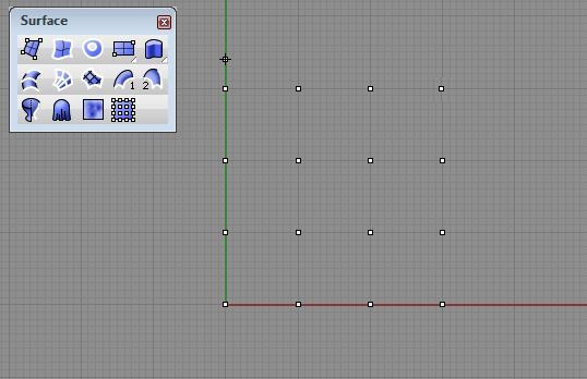
- create the grid of four by four points and the surface is generated
 |
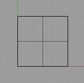 |
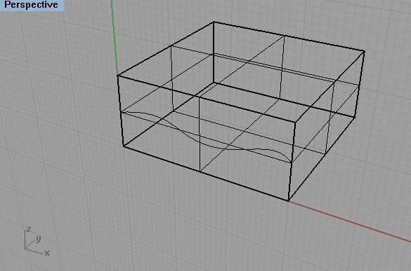
- alternatively, create a planar surface by two corner points, and use the command line "rebuild surface" to rengenerate the surface with 4 x 4 control points:
 |
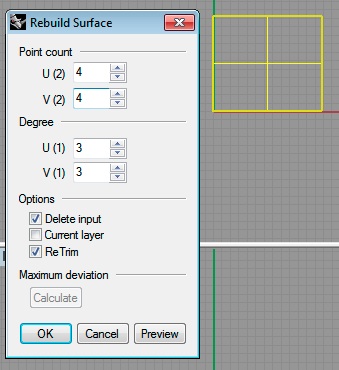 |
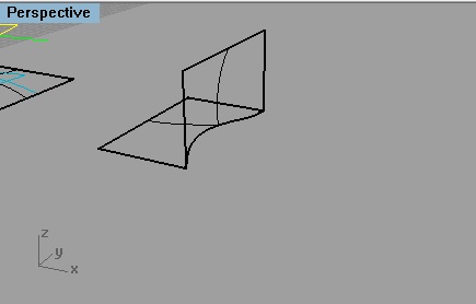
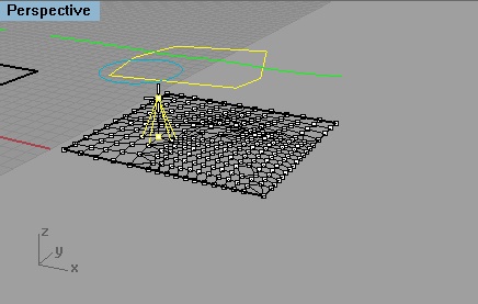
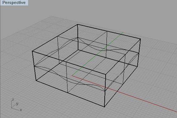
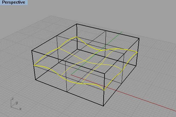
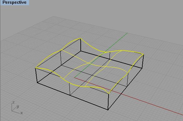
- Choose the control-points on tool and select the surface.
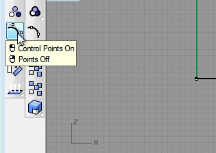
With the "ctrl" key selected ("ctrl" & "shift" key on an Apple keyboard), select and elevate points to make wavy surface.
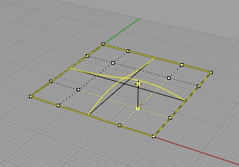
before after
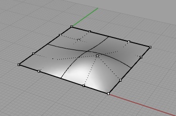
- view the surface with simple shading directly in the viewport
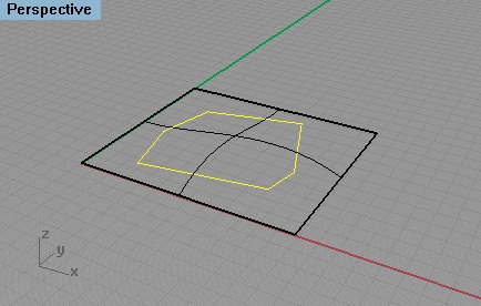
- turn off the display of the control points, change the active layer and color -> draw a closed polyline shape on top of the planar surface
- change the active layer and color -> draw a circle on top of
the
planar surface
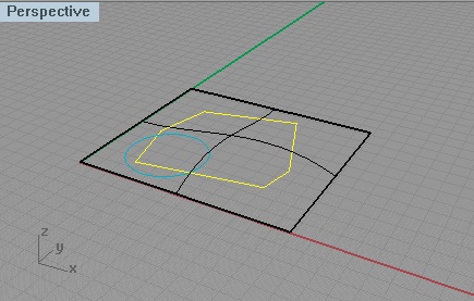
- change the active layer and color color -> draw a bSpline on top of the planar surface
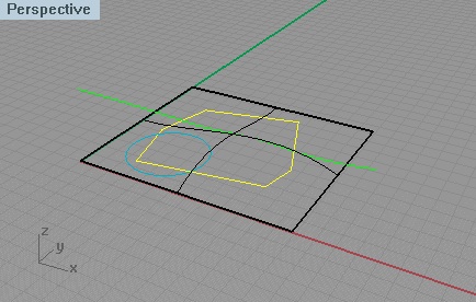
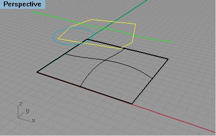
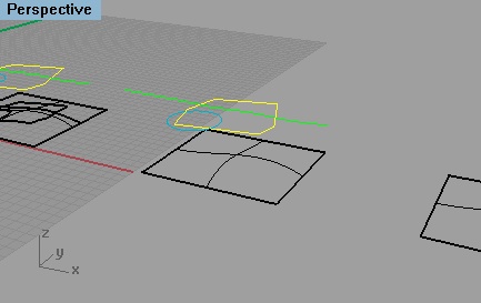
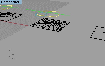
- grab all three elements and use the Move tool to reposition them to hover above the surface.
- In the "top" view, grab all the entitites- and use the Copy command to make three Copies to the side
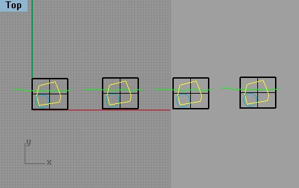
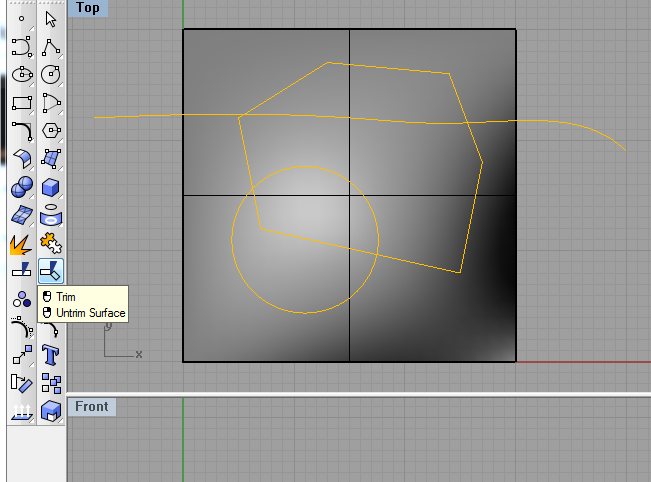
- Zoom
to first surface
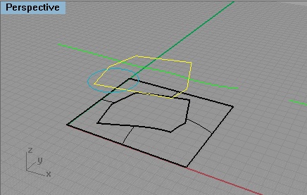
- Select Trim surface tool
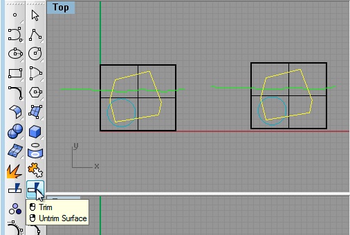
- Select
the polygon, enter the "return" key (or
right-mouse click), select the surface area corresponding to inside the
boundary of the polygon, and the enter the "return key"
- Note where grabbing surface -
internal or external to projection is portion deleted
- Do the same command again with Circle
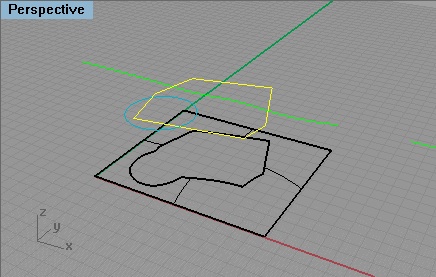
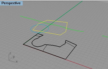
- Do the
same command again with bSpline
- note again which side you grab on surface matters to what is retained.
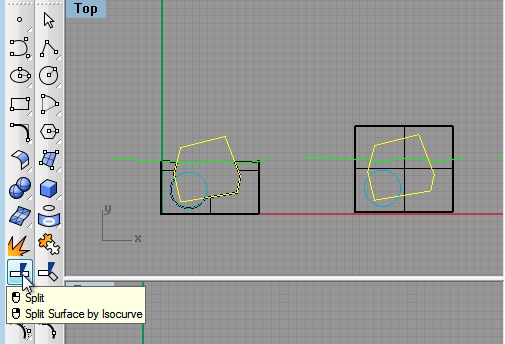
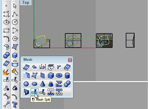
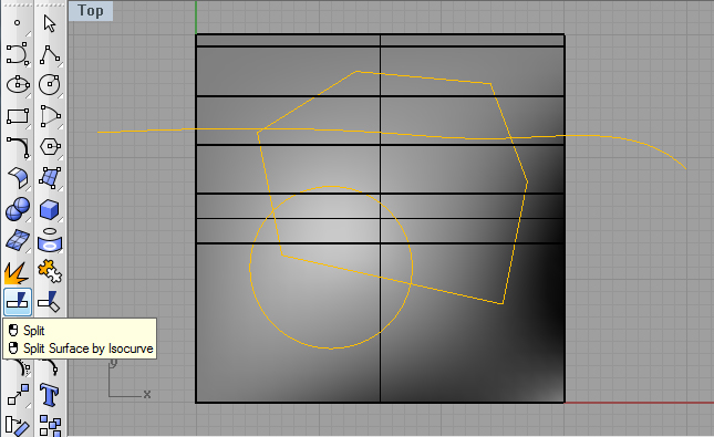
2. Now
revisit the the same geometry, but this time, split, rather than trim
the surfaces with the "split surface too".
- Change settings to Split Surface - test for polygon, circle and
bpsline.
- similar to before, select the surface to split, enter the "return"
key (or right-mouse click), select the polygon to perform the split,
and enter the "return" key (or right-mouse click)
- similarly, use the circle to split both surfaces by first selecting the two surfaces, enter the "return" key (or right-mouse click), select the circle to perform the split, and enter the "return" key (or right-mouse click)
- simlarly, use the bspline to split the two new surfaces below it
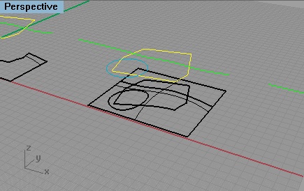
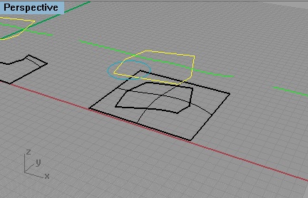
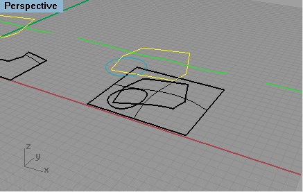
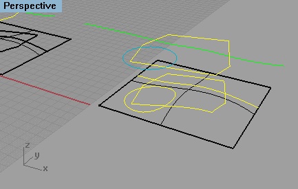
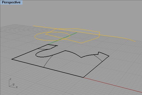
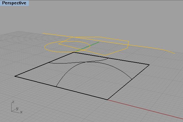
3. Change to Method to Project Curve - repeat the command on the above three elements
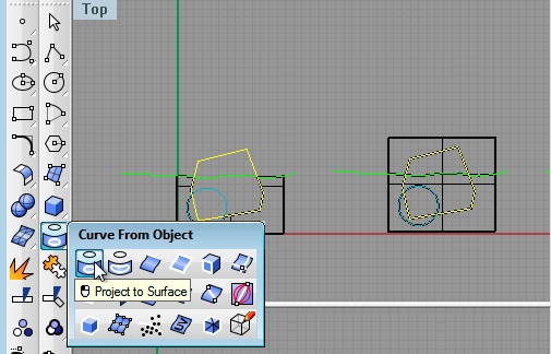
- on the 3rd copy of the original entities, select the polygon, circle, and bspline, enter the "return" key (or right-mouse click), and then select the surface below
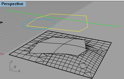
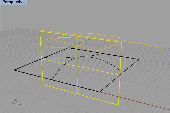
4. Now, we will apply the trim surfaces tool to split a surface with another surface.
- on the fourth copy of the original surface, rotate a copy surface upon itself fron the "front" view
- Use Trim Surfaces tool from before, select the rotated surface first,
enter the "return" key (or right-mouse click), and then select portion
of the surface below to be trimmed away second.
- Similarly, use the trimmed horizontal surface to trim the lower portion of the rotated surface.
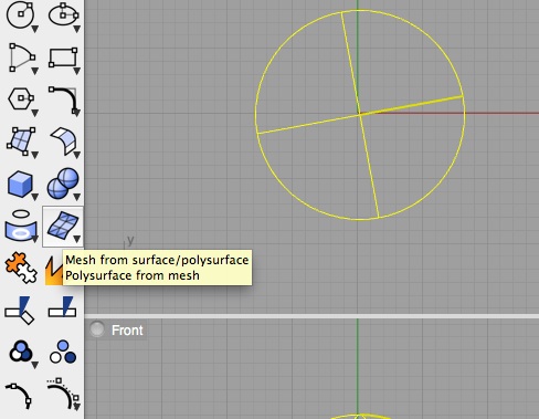
5. The mesh tool converts a bspline surface into a faceted polygon surface.
- Go back to the third copy of the original surface, polyline, circle and bspline, and erase the projected elements.
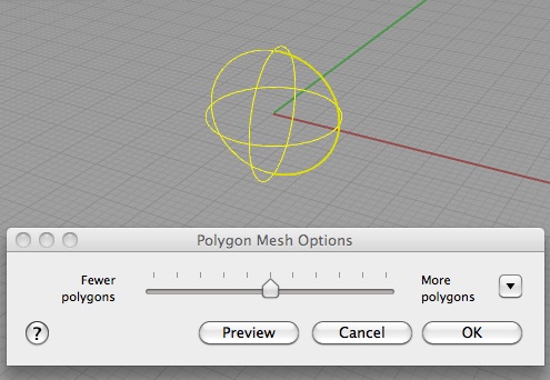
- Select the Mesh from Surface/Polysurface tool
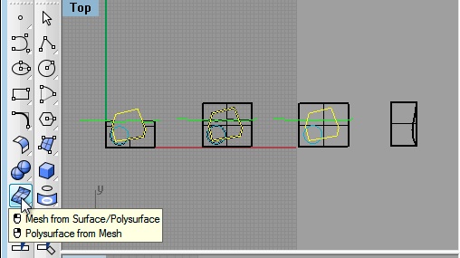
- Select the surface on the ground, and in the dialog box that follows, choose the default middle number of polygons, and enter "OK"
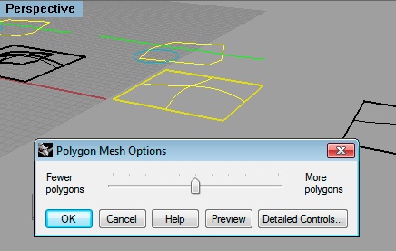
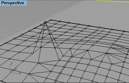
- A polygon mesh is now superimposed on the original surface.
- Turn on the control points, and move individual points on the mesh as was done with the original surface at the beginning of the workshop
- Note that the result is faceted rather than smooth as in the case of the original pre-meshed surface
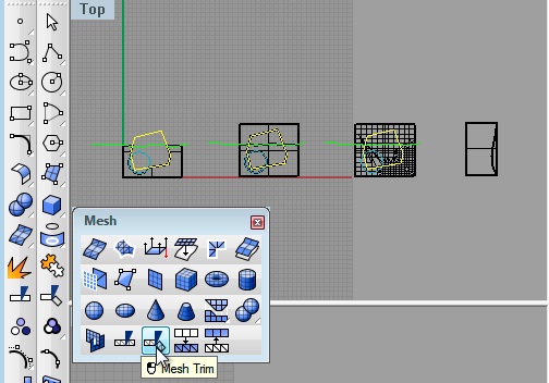
- Turn off the control points on the mesh. Note that the command MeshTrim and MeshSplit tools can be used to trim to the mesh surface.
 |
 |
- For example, as was the case with the original surface, select the "Mest Trim" tool, select the polygon, enter the "return" key (or right-mouse click), and then select portion of the mesh below to be trimmed away

Note that a portion of the original mesh was modified by moving a control point earlier. This portion of the mesh may need to be trimmed separately. Compare the image below where the "Mesh Trim" tool was reapplied a second time with the image immediately above where the "Mesh Trim" tool was first applied. Several facets towards the left-hand corner of the hole are remove in this second pass.
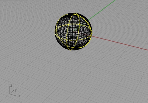
6. Apply mesh tool on simple solid sphere.
 |
 |
- Yields meshed sphere.
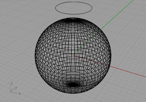
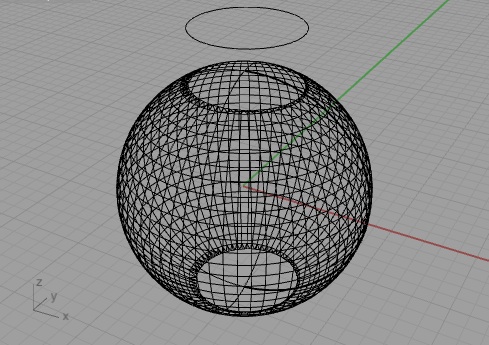
- Go back to MeshTrim tool- perform with a circle on the meshed surface. Similar trim results as before.
 |
 |
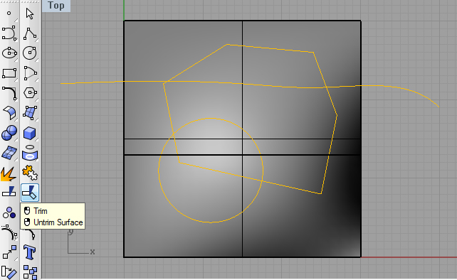
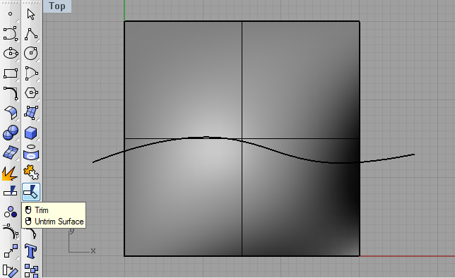
5. Reverse Method
- Remake the wavy surface with three cutting entities.
- Perform the trim surface command for all three entities.
 |
 |
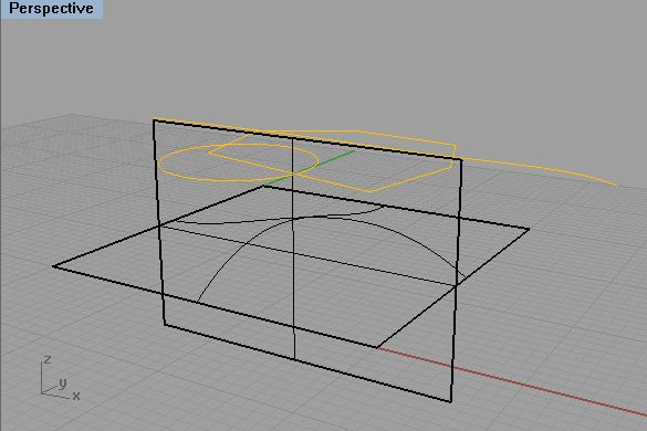
- Select the Untrim surface tool, selected the trimmed edge of the surface, and the surface will be restored.
|
 |
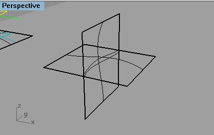
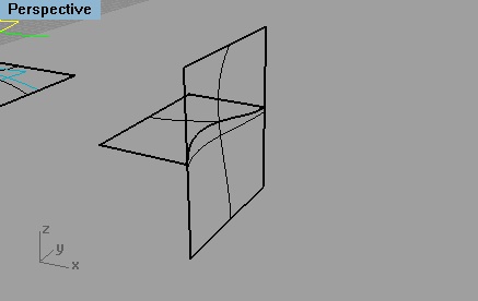
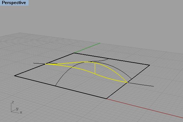
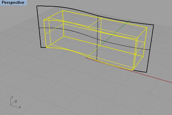
- Create a planar surface oriented perpendicular to the existing surface. Use the trim tool to cut the surface.
 |
 |
- Once again, select the Untrim surface tool, selected the trimmed edge of the surface, and the surface will be restored.
 |
 |
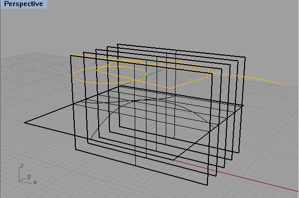
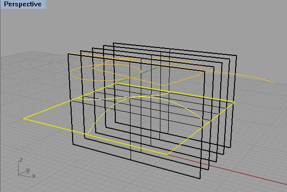
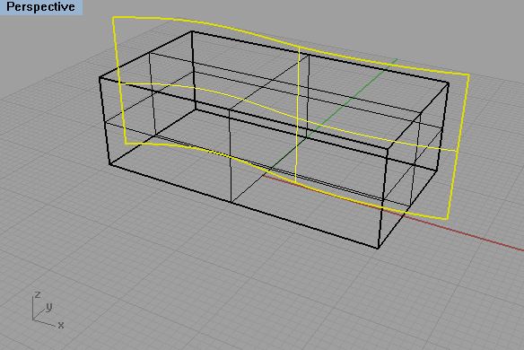
- Copy the vertical surface five times along the y axis, select the split tool, select the the horizontal wavy surface, enter the right-mouse button or the "return" key, then select the vertical surfaces, and enter the right-mouse button or the "return" key, and the ground surface is split into six surfaces. Note that there is no reverse option other than the undo tool.
 |
 |
 |
 |
 |
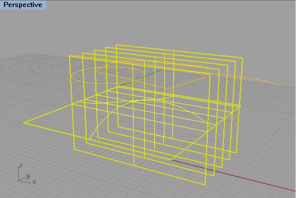
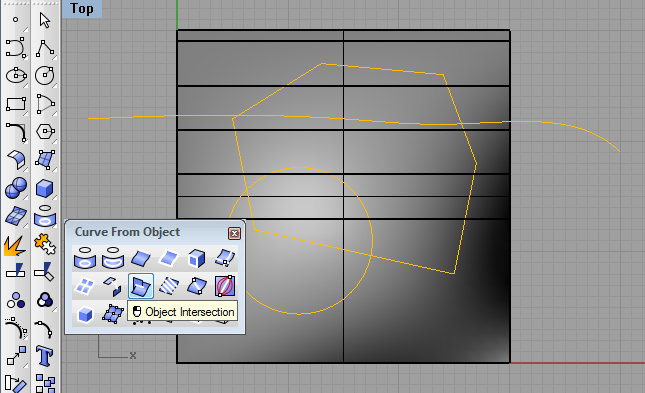
7. Object intersection.
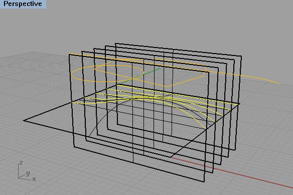
- For the same set of surfaces, select the object intersection tool, and then the horizontal surface and all the vertical surfaces, and the intersection curves are generated.
 |
 |
7. Linear Slices
-
Reduce the drawing downabove to the
original wavy surface.
- Go to the Top View orientation
- Draw a line over and bypassing the surface.
- Copy the line five times at equal
intervals so as to determine six total such lines..
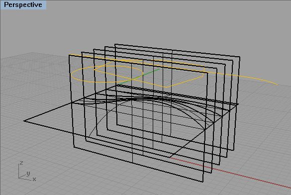
- Now using the object intersection tool, select the the horizontal
wavy
surface, enter the right-mouse button or the "return" key,
then
select the horizontal lines and enter the right-mouse button or the
"return" key
 |
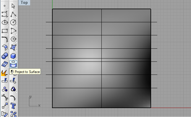 |
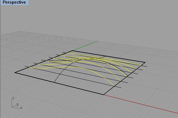
- and the ground surface is split into six sections:.
Triming surfaces can also be done with planar, non-planar and
non-linear elements.
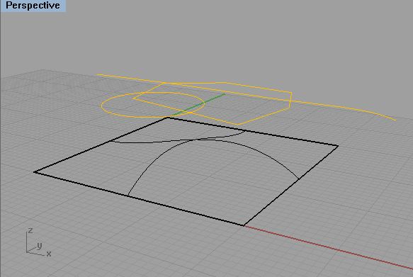
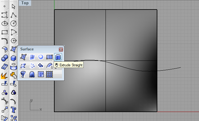
- draw a bspline at curving across the ground plane and then
extrude bsline
to get a singly curved upright plane.
 |
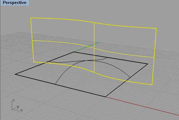 |
-Use the trim suface tool, select the horizontal wavy surface, enter the right-mouse button or the "return" key, then select the extruded surface, enter the right-mouse button or the "return" key, and get a continuous vertical surface section:
 |
 |
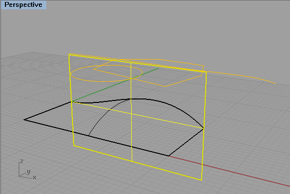
8. Slicing a solid with a surface.
The same trim command can be used to slice a solid with a surface.
- Create a solid box, and extrude a bspline curve through the box.
- Select the trim surface tool, select the extruded bspline, enter the right-mouse button or the "return" key, then select the portion of the solid box to remove, ,enter the right-mouse button or the "return" key, and you get a sectional slice of the box.s
 |
 |
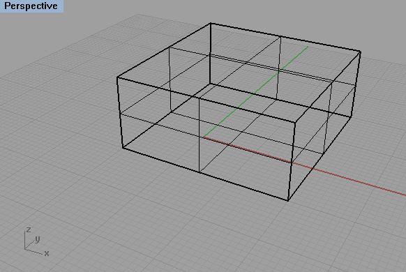
9. Cutting a solid with a doubly curved surface.
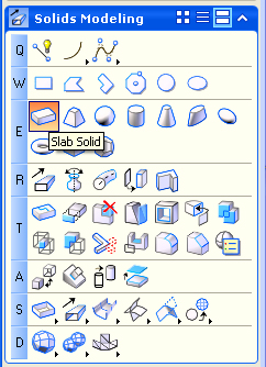
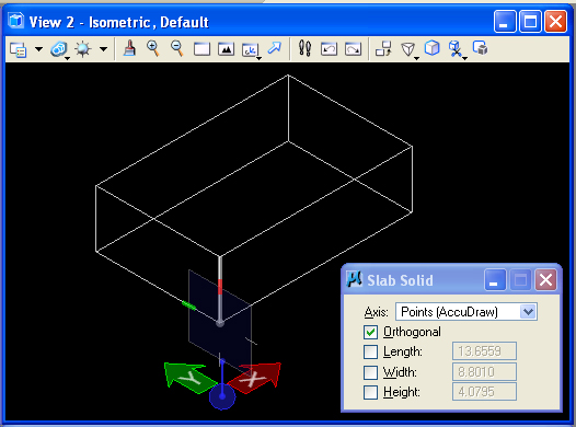
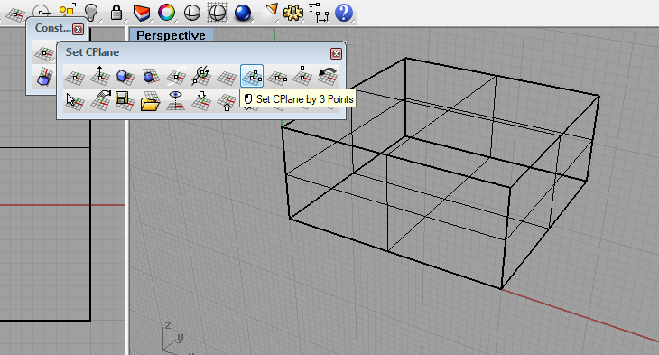
1 In the Solids Modeling tools, create a solid box.
- Using the "Set CPlane by 3 Points" construction plane tool, determine a construction plane on the front face of the cube
- Using the "mid" snap, draw a bspline on the front face of the box from the mid-point of one corner to the mid-point of the opposite corner.
- Similarly, draw bsplines on the other three faces of the solid, end-to-end with the first bspline.
- Now, using the "Surface from Edge Curves" tool, select the four splines and generate a doubly curved surface.
 |
 |
- One again, using the trim surface tool, use the doubly curved surface to trim off the upper portion of the solid box.
(SHOW ONLY)
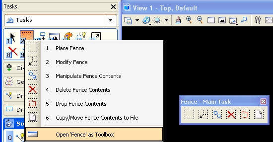
PART II: FENCE TOOLS (MICROSTATION)
Fence tools allow
you to select a portion of a view window and to perform operations on
it, such as editing, deleting, moving, copying, rotating, scaling or
stretching geometrical elements. You can also render a
sub-portion of a window through the use of a fence tools. The
fence tool is projected into the view window to perform these various
operations.
1. Copy and Clip Operation
Within
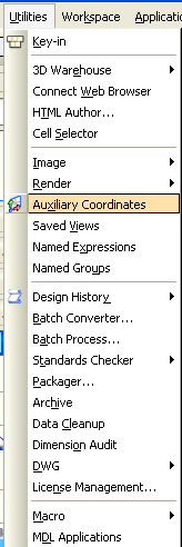
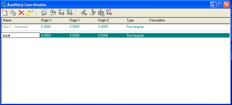
MIcrostation V8i, start a new drawing, open the
Utilities>Auxiliary Coordinates dialog box. Use
the save ACS icon in upper left-hand corner and save
the current default ACS plane as "base".
 |
 |
|
|
|
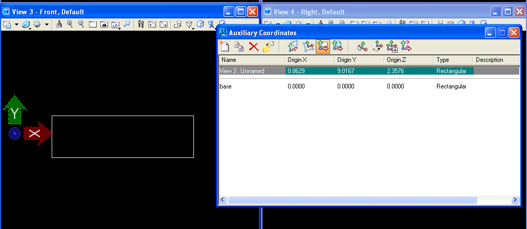
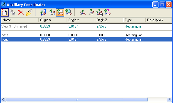
Save the new ACS as "front" within the Auxiliary Coordinates
dialog box.
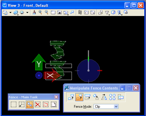
Open the fence tools subpalette from the main task menu (#2 key).
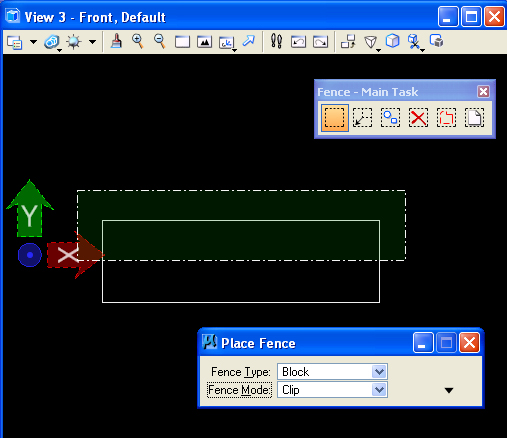
Draw
a "Fence" in the front view window with "Fence Mode" set to
"Clip". This mode isolates what's inside the fence from the outside.
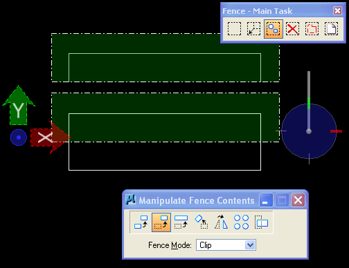
Select the "Manipulate Fence Contents Icon" (second icon in
the Fence palette) andnthe "Move" option, and enter two data
points in the front view with to clip off and move upward the geometry
that is encompassed within the fence.
Similarly, select the top
view window. Select the "base" ACS form the Auxiliary Coordinates
Dialog box, and repeat the same move operation on the upper
"Y" axis portion of the cubes from the top view.
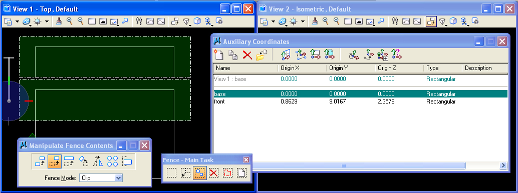
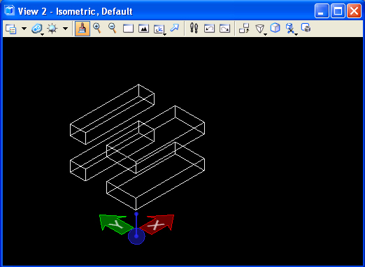
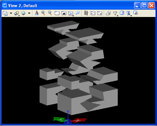
The result of the preceding two operations is to splice the slab into four slabs. Note that the fence tool in the top view operates on upper visible slab as well as the occluded lower slab in that view. That is, the fence projects the operation entirely through every object in its pathway in that view.
2.
Stretch Operation
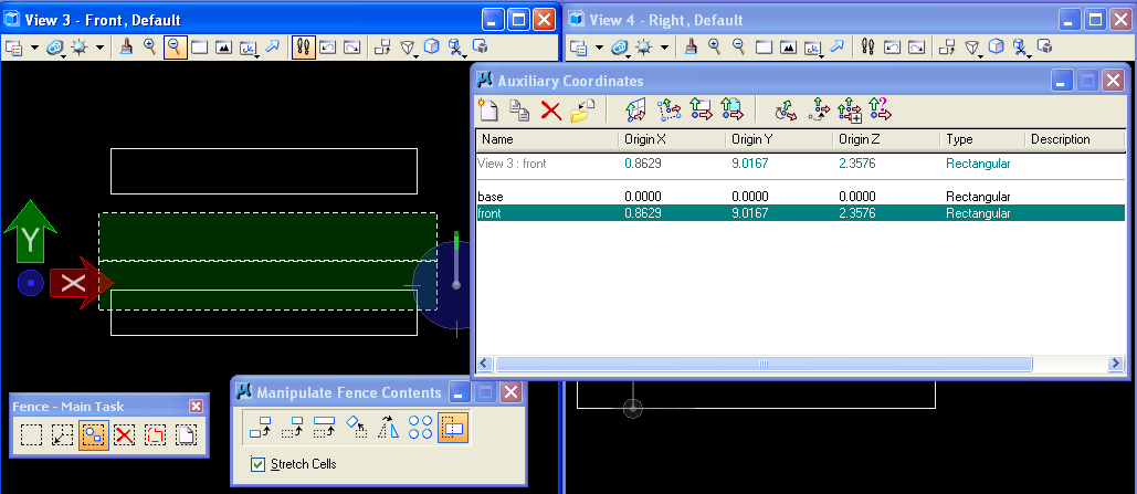
Re-select the front view, then select the "front" ACS in the Auxiliary
Coordinates dialog box, and place the fence over the slabs in
the lower portion of the view window. Next use the
"Manipulate Fence Contents" and "Stretch" tool option (shown
below) to change the height of the cubes on the ground plane..
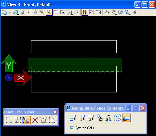
Once again, the fence projects the operation entirely through every object in its pathway in that view and they are stretched to have a larger "Y'" dimension. Note that a truncated cone (not shown) in similar situation would also have stretched in a tapering way preserving its tapering geometry. Similarly, other objects will also stetch appropriate to their geometry.
3. Non-rectangular Fence
Select the "Front" view and then the "front: ACS from the Auxiliary Coordinates Dialog box. Next, select the" Fence" tool, change the fence type to "Shape", and draw an arbitrary polygon over the front view.
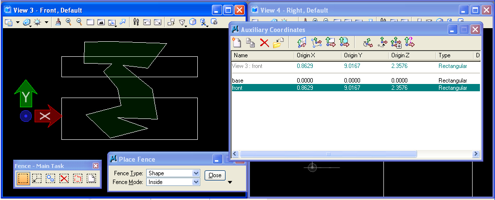
Zoom out of the "Front" view and use the "Manipulate Fence Contents/Move" option to clip the arbitrary shape to a location above the slabs. Note that the operation cuts the arbitrary shape out of the cubes and moves it above them.
 |
 |
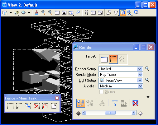
PART III. RENDERING WITH THE FENCE TOOL
The technique involves using a "key-in command". Go to the "Utilities/Key-in" menu and enter the command "render view raytrace" followed by the "return" key.

In View 2, draw a "block" Fence over a portion of the view window. In the Visualization, adjust the solar lighting using the W1 tool, select the "Render" (Q1) tool, and choose the "Fence" option. The result is that a smaller sample portion of the view window is rendered. This can be a very efficient way to sample the rendering quality without having to expend much greater time in testing the entire view window. Note that rendering 1/4th of the view window in Ray Trace will be significantly faster than doing the whole view.
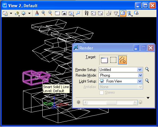
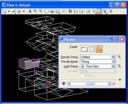
Note that the Render dialog box also allows you to render individual objects in several render modes, such as Phong or Smooth shading. This is achieved by pre-selecting the object you wish to render. Use the key-in command "Render View Phong" and then selecting the third icon in the "Render" dialog box as depicted below. Note that, this doens't work in Ray Trace mode (since the rendering algorithm is based on backward tracing of rays for every pixel in the rendered area.
 |
 |