COMPUTER
AIDED ARCHITECTURAL DESIGN
ARCH 2710: SEPTEMBER 18, 2025
Exercise 3: Transformations, Introduction to Solid and Surfacing Modeling
Due: October 10, 2025
Preview: Preview your approach by September 26thwith your SIA.
This assignment will introduce some of the techniques and concepts of three dimensional modeling. It is at signficant step forward for the semester in that you will undertake 3D modeling with an advanced use of construction planes for the first time. Later on during the semester we will be revisiting 3D modelng concepts with varied technology options and methods of working in 3D spac . Correspondingly, in future exercises you will also develop the geometry in your model with greater detail, more algoritmic reasoning, and with simulated lighting and materials.
For assignment 2, we had considered
symmetry operations through two-dimensiona diagramming of geometry. Now we use the diagramming geometry as a generative basis
for solid modeling and surface modeling techniques. The goal now is
to produce a minimally detailed massing model. A more indepth treatment of solid
modeling, 3D surfacing and parametric 3D modeling
will be explored in the workshops over the next several weeks.
NOTE: Start on this assignment early and work on it consistently over
the next several weeks. Seek out interim feedback on your progress or
on technical questions with your SIA or the course instructor. That is, work consistently and in smaller incremental steps over the period of
time prior to the due date rather than attempt to do the work in one final week of marathon effort.
PART I.
Overview: Four Steps In The Development of The 3D Model
PART II.
Develop a short abstract Grasshopper definition to describe some aspect of your project in 2D form. This can be a basic as a small set of lines in plan that are constrained to the movements of an associated set of points. Or, it can be a projection of a surface or a solid model in 3D.
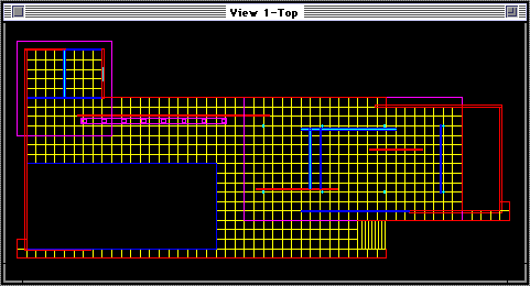
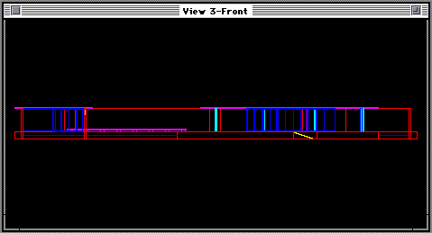
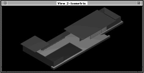
Note once again that you should not attempt to develop the 3D model in great detail, but only to develop a general representation of its massing and geometry. The following three figures show a rough development of Mies van der Rohe's German Pavilion largely done through box like projected solid geometry . Figures 1 and 2 are concist primarily of single line studies of the plan and elevation similar to what you produced in exercise 2. Note that similar types of architectural elements are grouped together by color and level so as to make the break down the study into more readily associated parts. Figure 3 describes a wireframe rendering of the solid geometry of the German Pavilion in three dimensions created by vector projection of 2D polygon line upward from the ground consruction plane. Figure 4 describes a simple shaded rendering of the same geometry now visible as mostly solid geometry elements, such as the varied type "solids of projection" projected upward from the ground construction plane within Rhino. Rather than just using solid, your own project may that you start with 3D geometries that require the used of both surface or solid modeling techniques we've developed in the workshops.
Figure 1: Plan Wireframe of Mies van der Rohe's German Pavilion.

Figure 2: Elevation Wireframe of German Pavilion.

Figure 3: Isometric Wireframe of German Pavilion.

Figure 4: Simple Shaded View of German Pavilion.

Developmental Sequence: Considering Geometrical Order in Your Approach
As you had done in exercise 2, re-examine the work of architecture or design in terms of the organization of its geometrical elements. For example:
1. take note of what
symmetries may be evident and explore the related use mirror, rotate,
and copy operations within the CAD system to revisit these symmetries
in 3D.
2. Attempt to understand your project as a
composition of abstract geometrical forms and consider how you might
approach the modeling process as one of a sequenced assembly of them. That is, see what you can do to start with simpler shapes and to apply the move, copy, mirror, rotate and scale operations to transform these in to more complete and complex shapes.
3. If applicable, explore the use of union, difference and intersection operations to apply Boolean logic to the construction of 3D model.
4. Use layers as a way to further give organizational clarity and to separate out geometrical
elements.
5. Optionally, explore the application of
"blocks" (also referred to as instantiated figures) to work efficiently with repetitive components which may only in scale, rotation, and location.
In order to get a feeling for how to schematically view the geometrical organization of a work of design, you may wish to again review some of the strategies evident the Precedents in Architecture textbook by Roger H. Clark and Michael Pause referenced in exercise 2. Tke note of its system of analysis where potential organizing priciples such as "Plan to Section", "Massing", "Unit to Whole", "Repetitive to Unique", and "Symmetry", that may be a relevant point of departure for a stepped sequence of 3d modeling. Similarly, the D'Arcy Thompson's book On Growth and Form describes sequential geometry steps particular to case studies of plants and animals that provide examples of a procedural set of step moving from 2D into 3D modeling.
6. As an important caveat, do not attempt to build a completely detailed model. Rather, take on an aspect of your case study and develop it more abstractly with an emphasis on geometrical composition. We will later learn more efficient ways of handling details and and determining more concretely how to advance the construction of the case study.
Submit a Rhino (.3dm) file for Part I showing the basic compositional elements of your design object. Submit a more abstract second Rhino (.3dm) file and at its associated Grasshopper (.gh) file for Part II.
Provide a short assignment description via email
that corresponds to your drawing and that describes important levels, views,
problems, and anything else of interest about your process and challenges in completing the exercise.
Place your Rhino and Grasshopper files in the "exercise 3" subfolder of the "submit" folder on CLASSES that you used for the prior exercise and then send email to Earl Mark, ejmark@virginia.edu and the SIA assigned to you describing within one or two paragraphs your efforts, anticipated goals, and insights into the geometry of your case study. Please just send the email with regular text and place your model, and if you may need to, any relvant images into your submit folder for exercise 2 on the SARC-CLASSES file server.