COMPUTER AIDED ARCHITECTURAL DESIGN
Drawing Assistance and Floating Construction Plane

 The
Accudraw tool was built by Bentley (the company that makes MicroStation)
as a mechanism to mimick the way that we use a Mayline or T-Square and a Triangle.
The tool was built to provide the designer with the ability to float around the
model with fluidity and control the input of points, distances, and other locations
quickly and precisely, in 2 and in 3 dimensional space.
The
Accudraw tool was built by Bentley (the company that makes MicroStation)
as a mechanism to mimick the way that we use a Mayline or T-Square and a Triangle.
The tool was built to provide the designer with the ability to float around the
model with fluidity and control the input of points, distances, and other locations
quickly and precisely, in 2 and in 3 dimensional space.
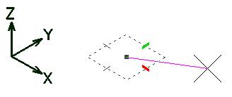
The centerpiece of the Accudraw system, the Compass, works as a floating
construction plane that can be moved and oriented to suit the needs of the designer
on a moments notice. The compass graphic itself is a representation of the
current construction plane, with a localized origin point (the dot in the center),
and X and Y axis tick marks to locate and constrain drawing in each of the axes.
As noted in the picture here, the red tick always
indicates the positive X direction of the current
construction plane, and the green tick marks the
positive Y direction. There is no marked indication
of the current Z direction, (after all this is a construction PLANE), but the
Z can always be determined to propogate perpendicular to both the X and Y, and
its positive direction can be determined using the Right Hand Rule.
Drawing Basics , Coordinate
Systems, Construction Planes, and Accudraw , Shortcuts
and Commands
Drawing Basics using Accudraw
As a assistant to just drawing, Accudraw
contains a number of features to smooth your input of distances and locations.
While using it, you will notice a number of system reactions to what you are
doing. Each of these are established to help ease your input of coordinate
points into your model, and in many cases, Accudraw is anticipating what you
are trying to accomplish.
-
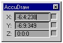 Coordinate
Readout: When you first started Accudraw (The T-Square and Triangle
icon), a coordinate readout window called Accudraw appeared on the
screen. As you move around your model, the window will continually
read back to you the coordinates of the point at which the mouse cursor
currently sits, in each of the X, Y, and Z axes of your current construction
plane. Coordinates read out here will be one of two types:
Coordinate
Readout: When you first started Accudraw (The T-Square and Triangle
icon), a coordinate readout window called Accudraw appeared on the
screen. As you move around your model, the window will continually
read back to you the coordinates of the point at which the mouse cursor
currently sits, in each of the X, Y, and Z axes of your current construction
plane. Coordinates read out here will be one of two types:
- If you are not within a drawing
or manipulation command (i.e. you're just floating the mouse around the
screen without any specifc tool selected) the readout will give you ABSOLUTE
coordinates, referenced in the base coordinate system of the entire model,
known as the World coordinate system in AutoCAD or the Global coordinate
system here in MicroStation.
- If you are actively placing
a line or other object, performing a move, or performing an other type
of modification of an element, then the coordinates read out to you will
be RELATIVE. Relative coordinates are based upon a floating
point of origin. The dot in the center of the accudraw compass indicates
the location of the current localized origin point, and all coordinates
read out are distances in each axis relative to this point.
- Axis Lock: As
you move the mouse close to or in line with one of the axis tick marks (positive
or negative directions), Accudraw will snap the line that you are drawing
directly into that axis and highlight the line in a bright white color.
This is a form of Axis Lock that Accudraw is using to constrain your
pointer interactively. When the line is snapped into one of these
axes, you will know that that line is propogating directly along that axis
and not at all off of it. You can confirm this by looking at the coordinate
readout window while your line is snapped into its axis. The axis
that you are in will have a distance, but the other two axes will (and must
if this condition is true) contain only 0's. This ensures that you
are locked perpendicular to that point along the given axis.
- Anticipating Your Moves:
Moving the mouse in each of the axis directions will reveal another feature
of the coordinate readout window. As you move in a given direction,
the blinking cursor of the coordinate input field (to type in numerical
distances) switches back and forth between the X and Y axes, depending on
which you are moving the mouse near. If you drag the pointer in the
Y direction, Accudraw assumes that you want to input a distance in that
direction, so it saves you a step by putting the cursor in that field for
you. As you move to the X direction, the cursor changes positon to
the input for X, anticipating a coordinate to be input there.
- Edit Field Input:
One of the most significant time saving steps of accudraw's capabilities
is that you can input coordinate distances without having to move the mouse
into the coordinate input fields at all. Most computer applications
require that you place the mouse cursor in a desired editing field, click
the button to place input focus there, highlight the existing text, delete
it, then type in your new text and hit return. While this rather slow
and long winded approach is supported in accudraw coordinate input, it is
not at all necessary. Instead, simply drag the mouse in in the axis
that you want to move and type the distance on the keyboard directly.
Accudraw will pick up this input and use it along the axis that you moved.
As such, you could quickly draw a box, for instance, by dragging in the
X direction, typing a distance and confirming it, then just drag in the
Y, type the distance, then going backwards in the X, then finally down again
in the Y to complete the box. At no time did the mouse have to leave
the drawing window.
Coordinate Systems, Construction Planes,
and Accudraw
In 2D it is not very apparent,
but when we move into 3D, it will be clear that the Accudraw Compass functions
as a Construction Plane floating about within a defined Coordinate
System. It already shows you an origin and a set of axes, the basic
components of a coordinate system. When you draw, you are working
in a single plane as represented by those axes. This is a bit tricky
to get used to at first, but you should find it easy to worh with in time.
Coordinate Systems:
- A coordinate system is a quantifiable
definition of three dimensional space as defined by a starting point, called
the Origin, and a set of cartesian axes propogating outward from that starting
point. Each of these axes, X, Y, and Z, define the orientation of objects
found within a three dimensional volume.
- By default in any CAD system,
there is one base coordinate system that controls the 3D model arena.
This is known as the Global Cordinate System, and it can be equated to Longitude
and Latitude on the Earth. Everything exists somewhere within this coordinate
system and the location of any object can be described by giving a set of
coordinates in each of the three axes (longitude lines, latitude lines, and
elevation above sea level). The origin point for the Earth's global
coordinate system is the point aligned with the Prime Meridian (x=0), the
Equator (y=0), and Sea level (z=0). All other locations can be read
relative to this point. The CAD system's Global Coordinate System is
no different, with an origin point at 0,0,0 and x, y, and z axes propogating
from it. Every object you draw is located somewhere relative to this
system.
- In many cases, however, we don't
know or care where objects exist relative to the Prime Meridian, the Equator,
or Sea Level. Do you know the location of the point that you are sitting
at? What you do care about is the location of objects relative to other
objects or relative to one specific location in the Global system, and then
the distances to all objects relative to that point. As such, we have
the ability to create localized coordinate systems that act as a superimposition
on top of the Global system. Points that we place in the localized system
also exist in the global system, but we are locating them relative to something
of local and immediate interest rather than the less directly useful point
of global origin (prime meridian, equator, sea level). These localized
coordinate systems are called Auxilliary Coordinate Systems, as they are auxilliary
to the global system. Some of you may also know them as User Coordinate
Systems, since they are defined by you, the user. An example of such
a system would be State Plane coordinates (where the bottom left corner of
the state of Virginia is 0,0,0 and everything else is located relative to
that), or the edges of your drawing sheet in studio where the edges of your
building are aligned to the edges of the sheet without regard to the direction
of true north or longitude and lattitude lines. These are cases where
we simply don't care about the global coordinate system, so we disregard it.
- All CAD systems allow us to create
these Auxilliary Coordinate Systems by defining a plane with three points
(origin, a point on the X Axis, and a Point in the Y direction to make a Euclidian
(3 point's define a plane) plane.) These Auxilliary Coordinate
Systems can be stored and recalled for later use, and all provide a new and
distinct point of origin and directions for the X, Y, and Z coordinate axes
such that points can be located relative to them.
Construction Planes:
- A construction plane is, at first
glance, very much like a coordinate system, but if we look a little bit deeper,
we can see that there is a subtle and very important difference.
- A Construction Plane is like
a flat piece of glass that you draw on. This piece of glass extends
infinitely in both directions, but it can only exist as a single flat plane
at any time. By drawing on this plane, you place objects in space.
The Construction Plane is not a coordinate system, though. Here's why:
- A construction plane is a
PLANE - Two Dimensional - and therefore does not have a Z Axis.
A Z axis is implied by the locations of the X and Y axes, but the plane
itself does not propogate in Z. Anything you draw on the plane is flat.
- The Construction Plane is
located somewhere WITHIN a coordinate system. This one's a bit fuzzier.
Above, I describe how one coordinate system can sit within another coordiate
system. This is pretty much the same thing, but here, our flexibility
is greater. Take the piece of glass and move it around witin your
coordinate system. The coordinate system remains the same, but the
location of the construction plane can move about within it. The
construction plane can, and often will, be coincident with the coordinate
system, but it doesn't have to be!
This last statement is the most
difficult to understand and the trickest part of using accudraw. The accudraw
compass represents a construction plane, not a coordinate system. That construction
plane exists within a coordinate system (the Global one, or any other Auxilliary
Coordinate Systems that you create), and it helps you to place locations at points
within those coordinate systems, but it is not one itself. In many cases
it operates much like one, and in most cases you will not care, but this is the
distinction between them.
You will primarily be working with
simple construction planes within the global coordinate system. You will
do this by rotating your Accudraw Compass, usually into one of the standard
rotations - the Top, Front, and Side rotations (which double
as the bottom, back, and other side). Be very careful to notice that these
are rotations, not locations, of planes. The Top rotation exists at elevation
0 and at elevation 100. The difference is the construction plane's point
of origin - it's location within 3D space. The two planes are parallel
but they are not the same. Only their orientation toward TOP is the same.
Accudraw uses determinate rotations without locations as a flexibility for drawing.
It can be very disconcerting at first since they do not lock the location as
well. For that, you need to establish a coordinate system (ACS) to lock
to, and we will show you how to do this. For the most part, though, you
will not need to, as you will be referencing existing geometry. Flipping
between the various plane rotations will allow you to move about in 3D space
very quickly once you get the hang of it, without certain constraints associated
with what is called Plane Lock. Plane Lock is an option, though, for those
cases where it is necessary.
Shortcuts for Accudraw
Here is a list of the commands for using accudraw. These are all implemented
in MicroStation as one or two key shortcuts (just hit the one or two key combination
on the keyboard while drawing to activate the command).
Construction Plane Orientations:
T - rotate construction plane to orient to the top of the model
F - rotate construction plane to orient to the front of the model
S - rotate construction plane to orient to the sides of the model
V - rotate construction plane to orient to the computer screen (view
window)
RX - Rotate construction plane 90 degrees about the current X axis
RY - Rotate construction plane 90 degrees about the current Y axis
RZ - Rotate construction plane 90 degrees about the current Z axis
RQ - swing construction plane in its own plane to orient X and Y axes
differently. The construction plane remains in the same plane. The
X and Y axes point differently
Cordinate Systems:
RA - Create a New Coordinate System and align the accudraw construction
plane to it.
WA - Give the current Coordinate System a name and store it for later
use.
GA - Go get a Coordinate System previously created and stored and align
the accudraw construction plane to it.
Axis Filters and Drawing Aides:
O - Move the location of the construction plane as identified by
its origin. When used with a Tentative point or snap, this allows to Offset
from that point for drawing.
X - Filter only the X distance from the current pointer location
or tentative point and lock it. Free all other unlocked axes.
Y - Filter only the Y distance from the current pointer location
or tentative point and lock it. Free all other unlocked axes.
Z - Filter only the Z distance from the current pointer location
or tentative point and lock it. Free all other unlocked axes.
D - Filter only the Distance from the current pointer location
or tentative point and lock it. Free all other unlocked axes.
A - Filter only the Angle from the current pointer location or
tentative point and lock it. Free all other unlocked axes.
Enter - Lock into the closest orthogonal axis (Axis Lock) and constrain
points to be along it. (Toggle to unlock)
Space - Toggle between Cartisian Coordinate (X,Y,Z) mode and Polar (Distance,
Angle) mode.
I - Use intersect snap filter for single operation (same as choosing
this from the button bar)
N - Use nearest snap filter for single operation (same as choosing this
from the button bar)
C - Use center snap filter for single operation (same as choosing this
from the button bar)