MicroStation
Digital Terrain Modeling:
There are three basic steps involved
in creating a digital terrain model using MicroStation and Geopak.
- Scan and Reference a contour map
- Digitize Contours into MicroStation
- Process the contours into a surface
Terrain Model
1. Scan and Reference a Contour Map
We will assume that you already have a scaled contour map that has been scanned
into a raster image file. The file can be in any number of formats, including
JPEG, TIFF, and PICT.
The important thing to know is the size of the scan (in inches) and the scale
that the paper map was drawn in. The latter can be found on the paper map. The
second can be determined from the scanning procedure or from Photoshop's Image
Size function after the fact. Once you know these facts, you may proceed to
bring the image into MicroStation as an underlay.
- Starting in a Top View in MicroStation,
draw a simple Rectangle Block shape using Accudraw that represents the size
that the map occupies in real-world units. This calculation is simply the
product of the width (or height) in inches by the scale (ft per inch), yielding
measurements in feet for both width and height.
- Next, use the File menu
to choose the Reference dialog. Find the Display menu of this
dialog and switch the type to Raster. This is for referencing Image
files as opposed to other MicroStation CAD (Design) files.
- Select the Tools menu and
choose Attach and then Interactive. When the file selection
dialog appears, find the location of your map image file and choose it.
- The system will prompt you for
an origin corner of the image placement, so snap onto the lower left corner
of the rectangle and accept it. Then, while rubberbanding (move the mouse)
to the upper right corner of the rectangle, snap to this point and accept
to place the image. A progress bar will show in the lower right while the
image loads, and then it will appear fit to the rectangle.
2. Digitize Countours into MicroStation
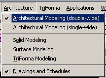
Bentley Architecture has within it a complete set of tools for drawing and later
processing contour and terrain model information. These tools are located within
the main Architectural Modeling Tools palette, which can be found under the Architecture
menu of Bentley Architecture.
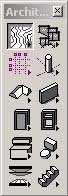
Once you have these tools on screen,
choose the first tool - Place Contours.
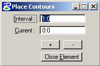
The floating dialog box gives the following options:
The Interval is
the between-contour elevation difference from your contour map. You might
be looking at every 1 foot contours (as shown), or every other (2 foot),
or possibly 5 foot, 10 foot, 20 foot, etc. This is determined by your map.
The Current setting is the contour
elevation that you are currently drawing. You will set this to the proper
elevation for each contour as you draw it.
Begin to digitize contours on screen
with the mouse. The contours will be drawn as curved lines.
When you have finished one contour, right-click to end it, then hit the [
+ ] button in the floating window to increment the current elevation to the
next step as per the interval. Continue drawing the next contour.
- As you digitize contours, they
are placed at the proper elevation automatically (by your setting/incrementing
the elevation
value) and they will appear three dimesionally if viewed from an isometric
or similar point of view.
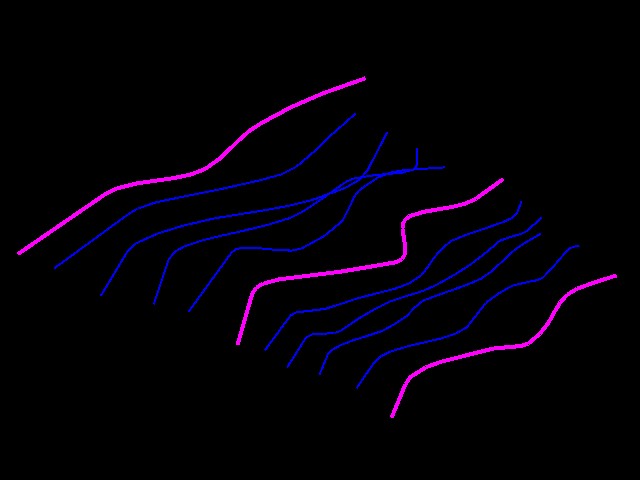
- You might also choose to control
the color that you are drawing with (using standard drawing color selection
tools) to give the map a more complete look and feel. In the drawing below,
every 5th contour is highlighted in a different color to create a major
/ minor contour diagram for ease of readability.
3. Process the contours into a surface Terrain Model - Geopak Method
Now that you have contours, you need to process that data into a series of files
that will successively build a terrain model. The files are as follows:
- Extract Contours to a Data File
(.dat)
- Process Data into a TIN - Triangulated
Irregular Network (.tin)
- Optionally Process the TIN into
a Lattice Grid (.lat)
Start with loading Geopak:
- To begin, you need to load and
open the DTM tools made by Geopak. These are found in the Applications
menu at the top of the screen. If it has not already been activated, Activate
GeoPak.
- Once it has been activated, in
this same set of menus under Application you will find GeoPak Site,
and then the DTM tools. Load these and you will see their palette on screen.
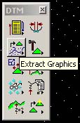
The First Step - Extracting Graphics
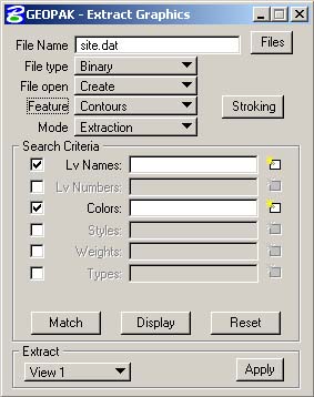 |
Using Extract graphics,
create a Data file of your own (this is a file external to
MicroStation),
and select the type of information (feature) you will be extracting
into it. This will typically be Contours.
Establish via the
Selection Criteria which levels, colors, types, etc. that will
be selected as Contours. The system does not know which things
are contours on its own. You MUST use this to tell it. Usually
levels is enough.
You can use the
Match button to graphically select a contour on screen to
match the level / color settings of that abject. This will
then grab all similar objects that match that same criteria.
Use
the Display button to verify that you are getting the right
elements.
If so, make
sure that you can see all elements in the View indicated
at the lower left, and click Apply. The calculation
is very fast. When done it will tell you "Extract View
1 complete." |
|
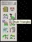
Step Two - Convert data file
to TIN
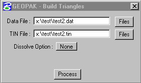 |
Once you have a Data file,
you must triangulate between its points to generate a surface description.
Using the Build TIN tool,
you simply choose the Data file to start with and a new TIN file to
create. Hit the Process button and the conversion will take
place.
When the process is complete,
again quite fast, the status bar of MicroStation will tell you "Build
Triangles Complete"
|
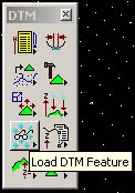
Step Three - Load TIN data into
view
Once the TIN file is processed, we simply need to display its contents to the
view and optionally write it to the MicroStation file for later use. This is
accomplished with the Load DTM Features tool.
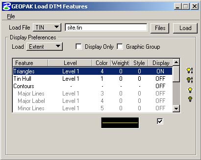 |
Using the Load DTM Features
tool, select the Type of file at the top left [DATA - TIN - LATTICE], and
the file to load from.
Next select the feature type
you wish to see, such as Triangles, and turn it on. At the bottom
of the
tool, symbologies for this operation are shown and are editable. Select
the Level, color, etc. that you wish to use for the triangles. Double-Click
on the colored line at the bottom to change these settings.
Turn off the Display Only
checkmark if you want to write these to the file instead of just look
at them.
Make sure no other features
are turned on by scrolling up and down the list of available feature types.
Click Load at the top right
to see the Triangles.
|
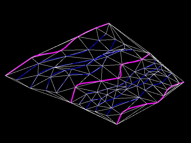
TIN mesh overlayed onto contour |
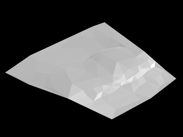
Rendering of TIN |