 Radiosity
Modeling and Rendering
Radiosity
Modeling and Rendering
Radiosity modeling and rendering
consists of a two phased process where 1) an energy model of light is
created, and then 2) the model is rendered using one of the available rendering
algorithms.
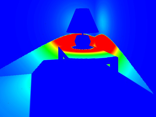
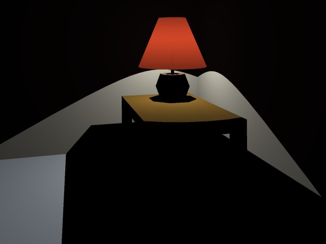
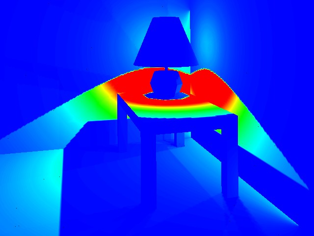
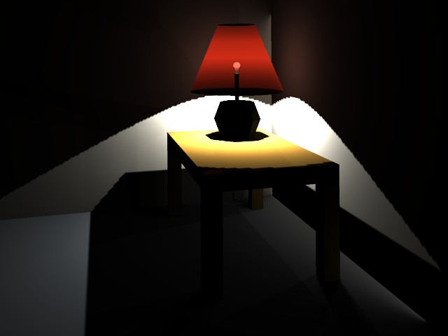
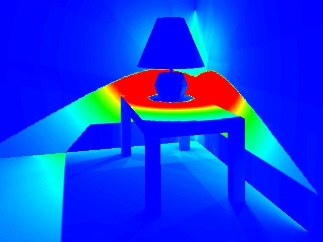
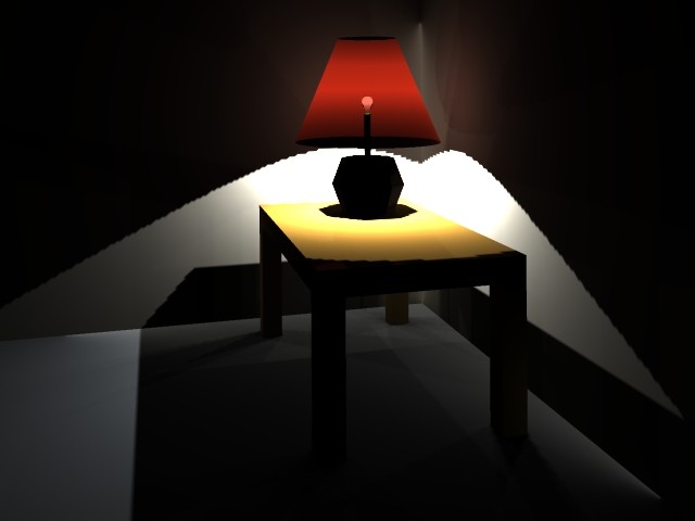
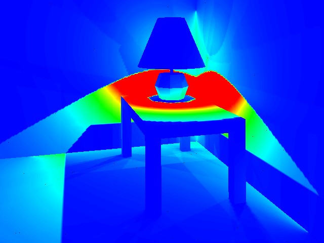
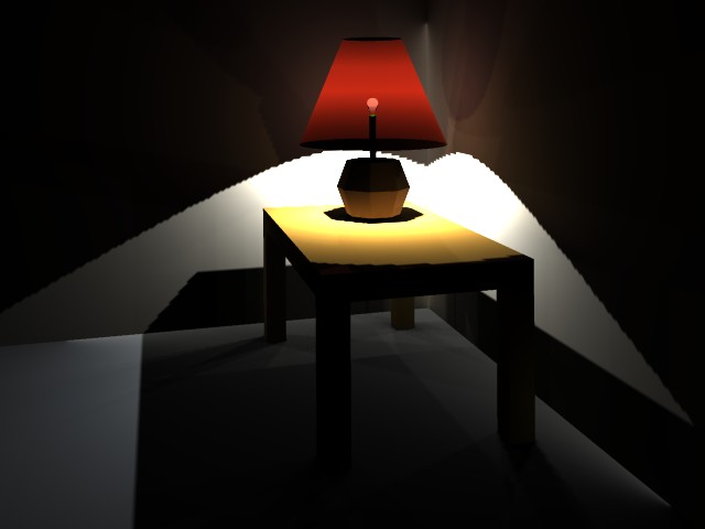
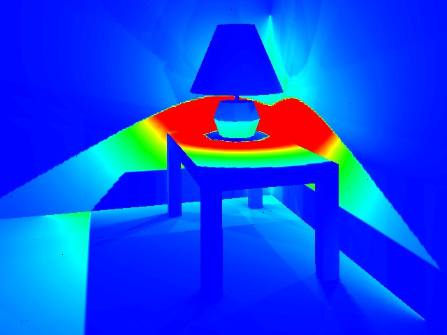
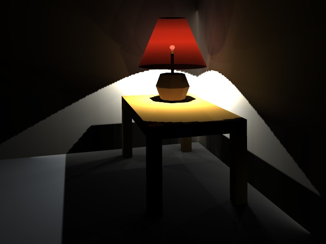
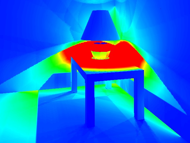
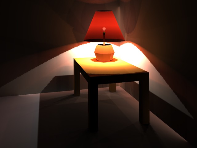
The example below demonstrates
a radiosity model generated for a specific number of "shots" and the
corresponding rendering of it. Each shot represents a bounce of light from a
light source. In the scene below, excerpted from a sample drawing file provided
by Microstation, we see the increasingly subtle rendering effects as the "shots"
of light accumulate through the model. We begin to see secondary and tertiery
shadows as the number of shots increase, a pneumbra effect. The left-hand image
depicts a luminance rendering of a given number of shots where energy levels
are depicted from blue to red. The right-hand image depicts a raytrace rendering
of the same energy model.
Example
| #
SHOTS |
Luminance Rendering |
Raytrace
Rendering |
| Shot
1 |
 |
 |
| Shot
2 |
 |
 |
| Shot
3 |
 |
 |
| Shot
4 |
 |
 |
| Shot
5 |
 |
 |
| Shot
100 |
 |
 |
The interface
to the radiosity modeling and rendering tool provided by Microstation is provided
in three panels of the radiosity modeling and rendering dialog box. These panels
present a set of options for controlling and optimizing the radiosity modeling
process. More details on the specifics of the radiosity modeling technique can
be obtained by reading the Radiosity Documentation PDF
file. This is only available for local viewing within the School of Architecture
at the University of Virginia. The annotations in the table that follow describe
some of the main parameters of interest.
| Radiosity
Modeling and Rendering Dialog Box |
| Panel
1 |
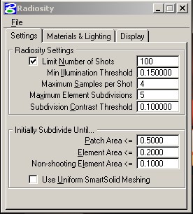 |
- Number of Shots
- Maximum number of shots allowed in solution.
- Min Illumination Threshold
- % unshot energy as limit on processing solution.
- Maximum Samples per
Shot - number of samples taken on a source patch of maximum size.
- Maximum Element Subdivisions
- limit on element subdivision resolution of shadow boundies (a value
of 1 allows an element to be split 4 times, a value of 4 allows an
element to be split 16 times).
- Subdivision Contrast
Threshold - relative contrast used to detect shadow boundaries.
- Path Area - Maximum
size of patch area in master database units (MU).
- Element Area -
Maximum size of element area in MU.
- Non-shooting Element
Area - Determines cut-off size for elements to become reflecting
only and non-shooting. Can set to 0.0, not really needed.
|
| Panel
2 |
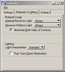 |
- Material Receives Light
- (1) "Always"
if all materials receive light; (2) "If Radiosity On", means
that materials receive light if radiosity property for material is
on ; (3) "If Radiosity Of", means that materials receive
light if radiosity property for material is off.
- Material Reflects Light
- (1) "Always" if all materials reflect light; (2) "If
Radiosity On", means that materials reflect light if radiosity
property for material is on ; (3) "If Radiosity Of", means
that materials receive light if radiosity property for material is
off.
- Illuminate Both Sides-
(1) "On" if both sides are to be illuminated; (2) "Off"
if only the side with positive surface normals are to be illuminated.
- Light Interpolation
- (1) "Standard" if fall-off in light intensity is linear
with distance; (2) "Extended "if fall-off in light intensity
is the square of the distance (realistic).
- Ray Trace Direct Illumination
- If on, ray tracing used to calculate shadows rather than being calculated
from reflected light.
|
| Panel
3 |
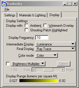 |
- Ambient
- Use unshot light to create ambient light.
- Wiremesh Overlay
- Include wiremesh overlay.
- Shooting Patch
Highlighted - Hightlight Shooting Surface patches.
- Display Frequency
- Number of shots between intermediate display of energy solutions.
- Intermediate
Display - Rendering method for intermediate energy solutions.
- Final Display
- Render method for final energy solution.
- Color Mode
- 24 Bit color or Greyscale
- Brightness
Multiplier - Adaptive brightness display of solution on a scale
of 0.01 (dark) to 100 (bright). Select button allows you to pick surface
for middle grey value.
- Adapt to Brightness
(alternative to Brightness Multiplier) - Adaptive brightness display
of solution in terms of lumens.
- Display Range
- Minimum to Maxium value for Lumens per square master unit.
|