
Workshop 6 notes, Week of October 11, 2007
Perspective, Lighting and Rendering
1. PERSPECTIVE
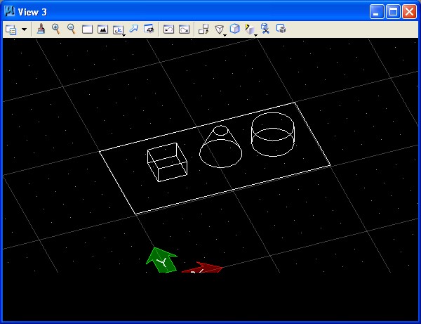
Create three platonic solids sitting
on a rectangle in the ground plane.
Enter "change view perspective tool"
from the view toolbar at the top of the front window.
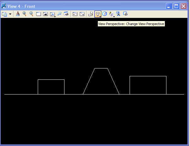
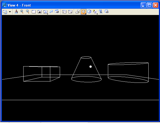
Drag the mouse from the center of
the window to the lower-left hand corner, and the perspective view takes
hold and becomes increasingly wide angle the further you drag the mouse towards
the lower-left hand corner.
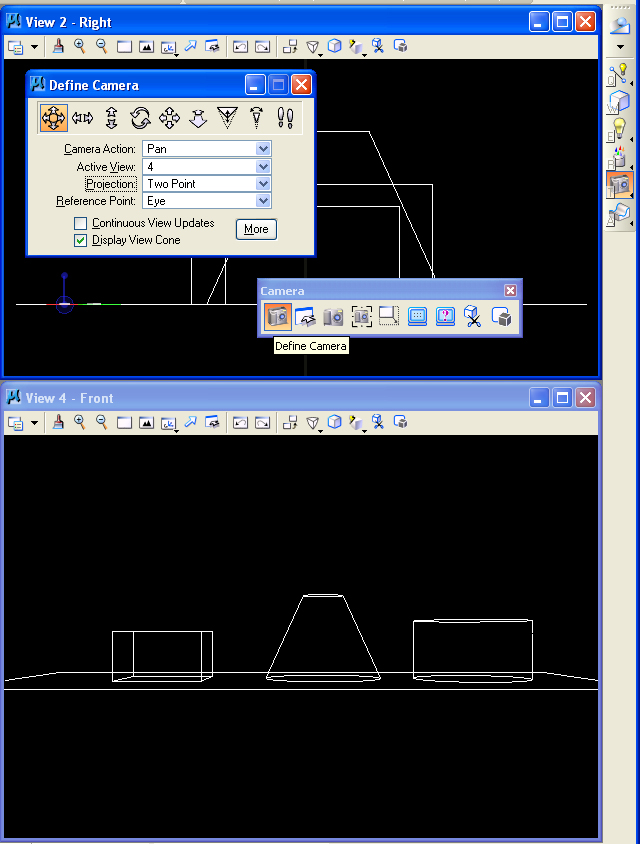
Alternatively, the "Define Camera"
tool is located in camera tools part of the Visualization module on the right-hand
side of the Microstation application window under the task-list options.
Invoke the Visualization module first.
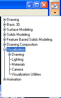
From within the visualization module,
select the "Define Camer" tool as indicated below. Choose two-point perspective
and also choose view 4, the front elevation view.
Work with the dolly camera icon
and turn own continuous view updates. Move the camera fowards and
backwards by moving the mouse from the center of the view window up and town.
Also examine the remaining perspective view controls.
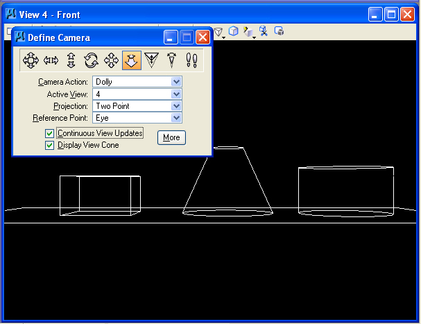
Note the camera view pyramid in
the other open views.
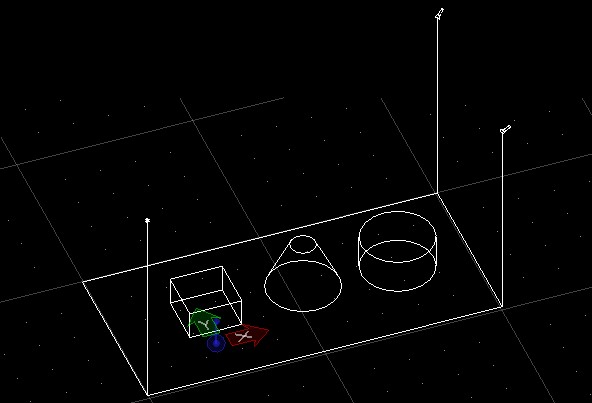
3. BASIC LIGHTING SETUP s
- Continue with the base rectangle
(with ACS snaps on).
- Turn off ACS snaps and use the
slab tool to place a slab on the rectangle surface (tentative snap a vertice,
hit "o" for "offset"and start drawing in the rectangle).
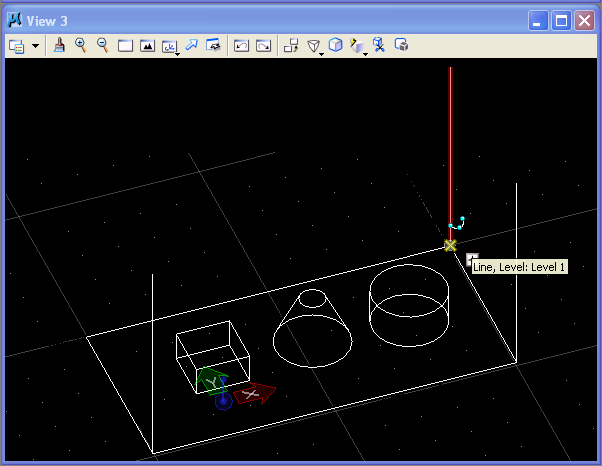
- Place three verticle lines at
the corners of the rectangle that will serve to locate two spot lights
and one point source light (for a fill light, key and back-key light).
 Using
the " Change Element Attributes " tool (In the main tool palette,
8 th one down on the left side), check off "color" and make
each of the three primitives a separate color.
Using
the " Change Element Attributes " tool (In the main tool palette,
8 th one down on the left side), check off "color" and make
each of the three primitives a separate color. - In View Attributes (from pull-down
menu upper left corner of view window), check to make sure that "constructions" is
checked on so that we can see the light fixtures, and then make sure plane
locks are off.
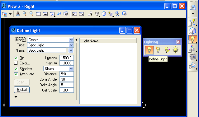
- Choose the "define light" tool
from the Visualization module on the right-hand
side of the Microstation application window under the task-list options.
- Using the
 "Define
Light" tool to create lights in the model as follows:
"Define
Light" tool to create lights in the model as follows:
- Make sure the mode is " create" and
place spot lights on two of the "poles" on the right-hand
side of the model (intensity of 1.0 and 0.75, key and back).
- Create point light (intensity
0.5) on the front left-hand pole.
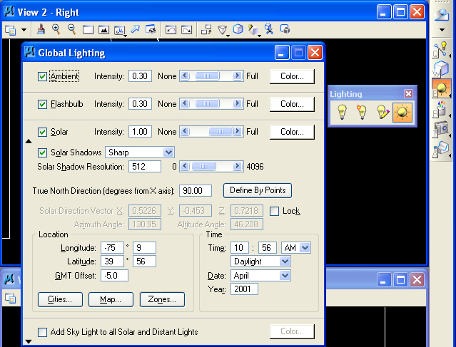
- Check global lighting and turn
off solar light by removing the check from the check-box below..
- Under View attributes, turn off
constructions so as to hide the light fixtures (the lights will still impact
the rendering of the model) and to prepare for rendering the model.
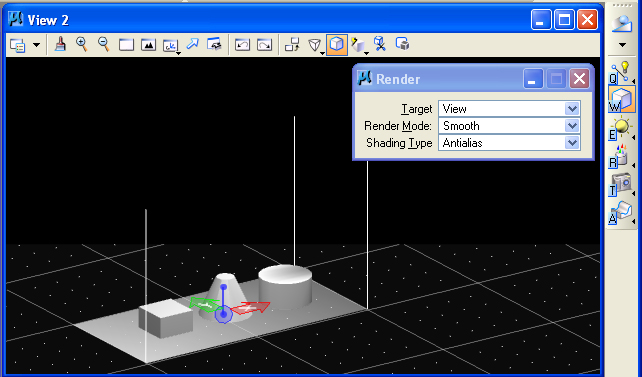
4. STANDARD RENDERING
Under the Render tools palette,
select a render mode (e.g., "Smooth Shading), turn-on Antialiasing and render.
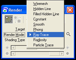
Explore in tern Wiremesh, Hidden
Line, Filled Hidden Line, Constant (Cosine) Shading, Smooth (Gouraud) Shading,
Phong Shading, and RayTracing. We will leave Radiosity Modeling and Particle
Tracing until later.
Each of these rendering types has
some advantages and disadvantages as we will learn to adapt appropriate to
particular needs.
- Wiremesh
- Hidden Line
- Filled Hidden Line
- Constant
- Smooth
- Phong (turn off or save shadow
maps under Settings>Rendering>General lighting)
- Ray Trace
- Ray Trace shading type: anti
alias
6. BACKGROUND MAP AND DISTANCE CUE
Settings>Design File>Views
- Browse for a Background image
and check off the box (C:\Documents and Settings\All USers\Application
Data\Bentley\Workspace\SystemMaterials\pattern\SkyBlueSmClouds.jpg).
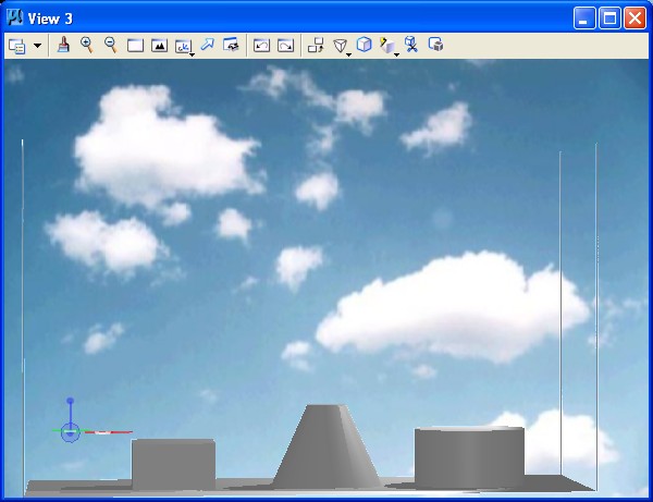
- Create Distance Cue as quick
way to give atmosphere to rendering.
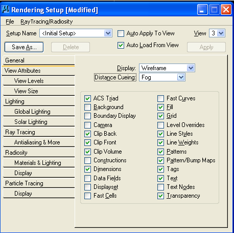
- Change " Distance cue" to " fog" .
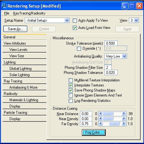
- It is also possible
to change near distance, density, or far density of fog
- In Settings>Rendering>General
menu, can change " Fog color" (pick light blue).
- Change "far density"
to 0.75 and, optionally, change "near density" to 0.25.
- To turn the background image
off background off, go to Settings>Rendering>View attributes or to
the the upper left-hand corner view pull-down menu>View
Attributes and check the background off.
7. SAVING RENDERINGS
- V iew size in Settings>Rendering>View
size.
- Set to 640x480 (make sure " proportional
resize" is off).
- Save image file by going to Utilities>Image>Save
(check options and save by browsing to folder).
- To see image in microstation,
go to Utilities>Image>Display .
8. SURFACE MODIFICATIONS
Tools>surface modeling>modify surfaces
Project Trim
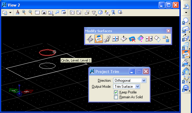
- Make rectangle in plan and make circle inside rectangle.
- Turn off ACS snaps .
- Move circle above the rectangle
(using the "F" or "S" construction plane).
 Use
the "project trim" tool on the modify surfaces palette (2 nd icon).
Use
the "project trim" tool on the modify surfaces palette (2 nd icon).- Make
sure "orthogonal" and "keep profile" are selected in the trim dialog box.
- Click on the rectangle, the circle, and left-click to accept.
Stitch Surfaces
- Draw a second rectangle adjacent to the first rectangle of equal width.
 Use
"stitch surfaces" (4 th icon) to join the two surfaces together.
Use
"stitch surfaces" (4 th icon) to join the two surfaces together.- Click on first object, second object, and left-click to accept.
Construct Trim
- Overlap a new rectangle over the second (in effect cutting partway into first).
 Use
"construct trim" tool (1 st icon).
Use
"construct trim" tool (1 st icon).- With"Trim first surface" option
selected, pick first and then second surface to trim.
- Left-click to accept.
Split Surface
- Pick surface with circular projected hole in it.
 Select
"split surface" tool (8 th icon).
Select
"split surface" tool (8 th icon).- Choose object then corner vertice.
- Move, and surface trims accordingly.
Extend Surface
 Select
the "Extend Surface" icon (9 th icon) and make sure "extend
mode" is "tangentia".
Select
the "Extend Surface" icon (9 th icon) and make sure "extend
mode" is "tangentia".- Select edge of rectangular surface and move to extend surface size.
Convert Surfaces to Solid
- Place rectangle and build 3D
elevations to create an "open container".
- It is possible to
make the sides by clicking on a vertice, moving to the ‘F’
or ‘S’ construction plane, tentative snapping the next
vertice and pulling up.
- Copy this rectangle to the opposite side, and create the other 2 sides.
- Use the "stitch surfaces" tool to join the rectangles together (click all 5 surfaces and left-click to accept).
 Use "Convert 3D" tool (3 rd icon), " convert to solid" option, to
convert to solid object (click ‘container’ and left-click
to accept).
Use "Convert 3D" tool (3 rd icon), " convert to solid" option, to
convert to solid object (click ‘container’ and left-click
to accept).
WILL REVIEW DURING THE FOLLOWING
MATERIALS DURING THE NEXT WORKSHOP
9. FILE
TYPES FOR TEXTURE MAPPING
These files are interchangeable
between drawings and are stored outside the .dgn file:
Material Palette File (file extension " .pal" ) –definition
of materials. Can be one of three types
- Definition
by properties [e.g. color]
- By procedure [by specific
algorithm]
- By texture mapping [literally
draping image onto a surface]
Materials Table (file extension " .mat" )
- References the palette files
according to object or a combination of layer and color.
10. SIMPLE MATERIAL ASSIGNMENTS
Settings>Rendering>Materials
- Go to Table>Save As to start a new table.
- Go to Palette>Open and choose C:\ProgramFiles\Bentley\Workspace\Triforma\atf_us_ncs\materials.
- Open " finishes.pal" and assign " flat warm grey" to the slab.
- Right-click on the finish.
- Go to " Assign,"
then choose the object. The material should then have a " +" next to it
and contain the layer and color of the object selected.
- Open palette " glazing.pal" and assign glass to sphere.
- Open palette " metals.pal" and assign brass to cone.
- Open palette " floors.pal" and assign tile semi gloss to rectangle.
- To preserve the new settings, right-click on the table name and save and then on the palettes to save.
11. PROCEDURE TEXT FILE
Settings>Rendering>Materials
- Palette>open and go to C:\ProgramFiles\Bentley\workspace\Triforma\atf_us_ncs\materials.
- Open " proctext.pal" .
- Assign " dutch bond" to brick slab, then render.
12. CREATE MATERIAL
Settings/Renderings/Materials
- Go to Palette> New and save " grue.pal" (can right-click to save or rename).
- Start new material " grue1" by right-clicking on the palette and clicking " new material" .
- Pick base color by clicking on the white square next to color.
- Adjust sliders for: Ambient Diffuse Specular Finish Transmit Reflect Refract.
- Add bump map by
clicking on the " pattern" button and switching the " Map" to " bump"
(Use StuccoBump.jpg from
C:\ProgramFiles\Bentley\Workspace\Triforma\atf_us_ncs\materials\bump).
- Reduce height to 0.50.
- Resave palette.
- Open up assign materials dialog box (Material>Assign).
- Open palette " grue" .
- Assign grue1 to cone.
- Render.
- Reserve for next time.
13 MODIFY PROCEDURE TEXTURE MAP & CREATE
YOUR OWN
Palette> Open
C:\ProgramFiles\Bentley\Workspace\Triforma\atf_us_ncs\materials\proctext.pal.
- Double click on " brick" .
- Double-click on procedure map for brick in assign materials dialog.
- Save palette as myproc.pal in your x: drive.
- Copy brick (dutch bond) to mybrick (dutch bond).
- Hit edit button, change mortar color.
- Save palette (note all names unique (palette and material)
14. TRANSPARENT OBJECTS
- COPY materials1a directly and files from classes folder.
- Relink individual person files
15. TO MAP IMAGE
- In the new palette, right-click
for "new material" .
- Hit the " Pattern" box.
- Click on the magnifying glass to browse for image.
- Turn off transparent background.
- Under "units" make
sure it is assigned to "surface" to stretch the image to the surface area (" Master" tiles
it in 1"x1" modules).
- In the model, build a new rectangle in a new color.
- Assign image to rectangle.
- Render to view.
16. ENVIRONMENTAL MAP
Table>environment maps
- Set environment maps (sky2.jpg).
- Select " raytrace.pal" and assign mirror to rectangle.
SEE ALSO :
http://www.arch.virginia.edu/arch541/Handouts/render/attrib.html {material attributes http://archweb.arch.virginia.edu/arch541/Handouts/render/rtraceset.html {raytrace attributes http://archweb.arch.virginia.edu/arch541/Handouts/render/setup.html {gen render attributes http://www.arch.virginia.edu/arch541/Handouts/render/viewatr.html {view attributes http://archweb.arch.virginia.edu//arch541/Handouts/sample.htm { sample marble