![]()
Workshop 3 Notes, Week of September 17, 2007
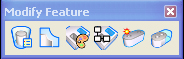
1. MODIFY TOOLS
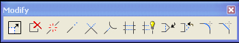
![]() Modify element. This very generic and useful tool can be used to alter a
primitive multiple ways, including: a point (by clicking on a point),
an edge (by clicking on a midpoint of a segment) or size of an element
(by clicking on a point of a circle, box, etc.).
Modify element. This very generic and useful tool can be used to alter a
primitive multiple ways, including: a point (by clicking on a point),
an edge (by clicking on a midpoint of a segment) or size of an element
(by clicking on a point of a circle, box, etc.).
![]() Delete part of an element breaks an element into two separate pieces and deletes a part of an element.
Delete part of an element breaks an element into two separate pieces and deletes a part of an element.
![]() Break a selected element at a point.
Break a selected element at a point.
![]() Extend line extends a line. There is also an option to type in the distance of the resulting length.
Extend line extends a line. There is also an option to type in the distance of the resulting length.
![]() Extend two elements to intersection extends two lines to each other
Extend two elements to intersection extends two lines to each other
![]() Extend element to intersection extends one line to another, or to an implied intersection.
Extend element to intersection extends one line to another, or to an implied intersection.
![]() Trim element cuts one object. Option: pre-select two elements with the control button to cut another.
Trim element cuts one object. Option: pre-select two elements with the control button to cut another.
![]() Intellitrim is more complicated than the regular trim element, which works in
most cases. It combines defining area to trim into the tool.
Intellitrim is more complicated than the regular trim element, which works in
most cases. It combines defining area to trim into the tool.
![]() Insert vertex
Insert vertex
![]() Delete Vertex
Delete Vertex
![]() Circular Fillet
Circular Fillet
![]() Construct Chamfer
Construct Chamfer
2. SELECTION / PRE-SELECTION
You can pre-select before using other tools to alter more than one element at a time.
a. ![]() Using arrow (aka element selection) tool, click and drag to make a rectangle around the things you want to select.
Using arrow (aka element selection) tool, click and drag to make a rectangle around the things you want to select.
b. ![]() Use arrow tool to click on individual elements, holding ALT button to add to your selections.
Use arrow tool to click on individual elements, holding ALT button to add to your selections.
c. ![]() Use power selector (arrow with light bulb). Offers different methods
(areas), modes ( add/subtract from selected elements), or click on
arrow at bottom of box to select by colors, element type, levels, etc.
Use power selector (arrow with light bulb). Offers different methods
(areas), modes ( add/subtract from selected elements), or click on
arrow at bottom of box to select by colors, element type, levels, etc.
3. ACS PLANE LOCK AND ACS SNAP LOCK
a.![]() Open the active locks menu, located in the bottom right corner next to the snap menu.
Open the active locks menu, located in the bottom right corner next to the snap menu.
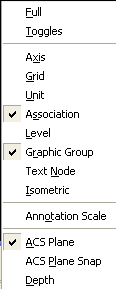
b.The ACS plane Lock forces the drawing plane to the ground plane.
c.The ACS plane snap Lock forces object snaps to attach at the ground
plane (this lock should be turned off for today's exercise).
There are a range of solid modeling options: shapes, extrusions, and smart solids.
4. SOLID PRIMITIVES
* To bring up the solid tools go to: Task Manager > Solids Modeling > 3D primitives.
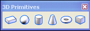
* These tools allow you to construct Slab, Sphere,
Cylinder, Cone, Torus, and Wedge by drawing a series of vectors to
describe that solid.
* The Slab, Cylinder, Cone, and Wedge all work in a similar fashion.
* When drawing a Sphere however, the very center of
the Sphere is placed along the ground plane. To move the Sphere up, get
into front view and use the move tool to move the Sphere up to the
ground plane by first selecting the Sphere, then typing " F" to move
Accudraw to the front orientation, and then finally move the Sphere. To
get Accudraw back onto the ground plane type " T" for top.
* For the Torus tool, it is good to type a value for
the primary radius, secondary radius, and/or angle in the place torus
dialog box.
5. BOOLEAN OPERATIONS
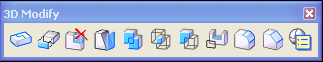
* To bring up the 3D modify tools go to: : Task Manager > Solids Modeling > 3D Modify.
* There are a variety of tools in this palette. For
now, we will just look at the basic Boolean operations: Union,
Intersection, and Difference.
* Construct Union: Combines two objects into one solid object (fifth icon from left).
* Construct Intersection: Creates a solid object as
the shape common to two elements (sixth icon from left).
* Construct Difference: Subtracts one object from
another. First, select the object to remain. Second, select the object
to subtract (seventh icon from left).
6. 3-D CONSTRUCT TOOLS
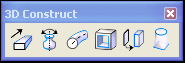
* To bring up the 3D construct tools go to: Task Manager > Solids Modeling > 3D Construct.
![]() *
Extrude: Makes a planar object 3-dimensional. The original 2-D object
must be a closed object. A group of connected smart lines can become a
shape using the Complex Shape tool in the “Groups” toolbar
(see 8 Groups Tools below) . Creates the group of lines into a
surface.
*
Extrude: Makes a planar object 3-dimensional. The original 2-D object
must be a closed object. A group of connected smart lines can become a
shape using the Complex Shape tool in the “Groups” toolbar
(see 8 Groups Tools below) . Creates the group of lines into a
surface.
* Click on the closed object to drag to desired height.
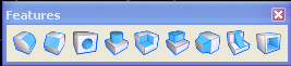
7. SMART GEOMETRY (“True Parametrics”)
Task Manager > Feature Modeling
![]()
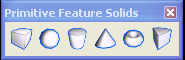
* Primitive Feature Solids(second sub-palette -
label "W"): Slab Feature/ Cylinder placed within the Slab Sphere placed
within Slab boundary

* Difference Tool (third sub-palette – label
“E”, third tool in palette) Select Slab to keep, then
object to create difference from, and left-click to accept
* Modify parametric solid/feature (9th sub-palette
– label “F”, first tool in palette) – Select
object; allows you to modify the dimensions of differences created by
feature modeling shapes. Try changing the dimensions of the cylinder.
Select it on its bottom.
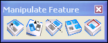
* Manipulate Feature (6th sub-palette – label
“A”, ”, first tool in palette)Move feature at
leftmost icon in sub-palette– allows you to move/copy the feature
model shape within the object. For example, move the cylinder inside
the slab (select the cylinder at its bottom).
* Features (seventh sub-palette – label
“S”) – allows to create a hole within the slab by
establishing a diameter then clicking on the object and moving the
whole into place switching surfaces on the slab simply by sliding
across it. (countersink holes can also be created), Use 3rd icon from
left in sub-palette.
NOTE: remember you can always look to lower left corner of the screen for any tool instructions
8. GROUPS TOOLS
From main tool palette on the left hand side of the screen, select the sixt sub-palette, labelled with "6".
![]()
Open up the sub-palette
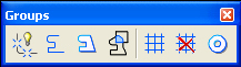
Drop element [Groups/ 1st tool] Makes separate pieces out of a single shape.
Create complex chain [Groups / 2nd tool] Makes a single line out of independent pieces.
Create complex shape [Groups / 3rd tool] Makes a single shape out of independent pieces. In order to extrude, you need to have single elements, typically made with this tool. See Methods above.
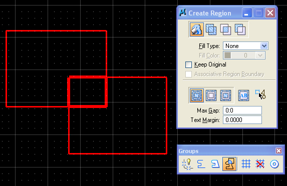
Create region [Groups / 4 th tool] Uses Boolean logic to make shapes out of the unions, differences, or intersections between two or more elements. There is also a flood option.
9. GROUP TOOL
Selected entities can also be grouped together to function as a single object through the use of the pull-down menu" group" tool under edit/group (or CTRL - G) as well as ungrouped under same menu through the "ungroup" tool (or CTRL-U).
