
Workshop 5 Notes, Week of September 22,
2008
ACCUDRAW, 3D CONSTRUCTION PLANES
& DIGITAL TERRAIN MODELING
Note: This workshop focused on a number
of digital terrain modeling methods. The primary method of concern is
reflect in notes captured under item #4 below. The other methods are
more advanced and extracurricular to the requirements of arch 541.
- The Accudraw Compass
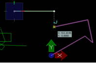
coordinate readout / entry in Accudraw
- XY(Z) axes
- Dynamic Coordinate Readout / Entry
- Precision input M:S (Master Unit : Sub Unit )
- AccuDraw Settings:Display – Display
Coordinates
- Spacebar or F11 – give AccuDraw input
focus
- Context sensitivity to gesture
- Just type in distance
- Last distance remembered, PGup/PGdn distance cache
for previous values used
- Popup calculator (+,-,*,/) Enter operation right
into Accudraw box
- Variables (pi) and parenthetical expressions can
also be used
- Spacebar change mode between polar and rectangular
coordinates
- Composite distances (X, then Y) and trackings
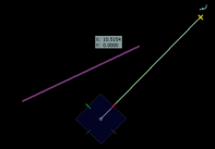
compass rotates to line
- Compass Follows you and rotates.
- Return to Top - T
- RQ – rotate quick (twist mayline)
- RE – rotate to element
quick locks – geometric alignments
- Quick Locks – geometric alignments
- Enter – Axis lock established by typing "X", "Y" or "Z"
- Lock X, Y, Z
- Measured distances (and calculations)
- Shift Origin - Letter "0"
- Snap shortcuts
- C (centroid, not just center)
- N (near, use with Axis lock for y=mx+b)
- I (intersect)
- K (divisor to subdivide element)
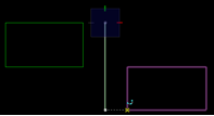
2. 3D Construction
Planes
rotation of accudraw compass
- V rotation
- T rotation
- F and S rotation
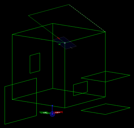
- Location and Rotation – Accudraw with snapping
in 3D-space
- Build a 3D box…
- O shift origin
- Rotate ACS
- RC – rotate to Current ACS
- RX, RY, RZ axial rotations
- RE – Rotate to Element in 3D
- Type ? for quickkeys help
3.
Polygon Mesh Objects:

solid sphere with control vertices exposed by using the select tool
- Create new file
Surface Modeling Task
menu
Create Solid Sphere
Mesh Tools > Construct mesh
Arrow Tool - Click to see mesh points
Click again on a point to edit / move
- Unfold Mesh
Mesh Tools > Modify Mesh > Unfold
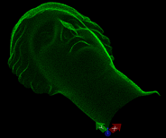
point cloud of head
- Mesh from Point Cloud
Tools > Annotations > XYZtext > Import
Demo Head – Point Cloud.txt
Construct Mesh – From Points
4. Terrain [KEY METHOD USED IN TERRAIN
MODELING]
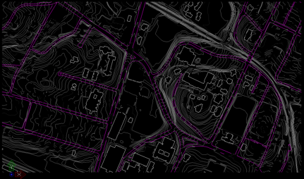
dgn file of Carr’s Hill
- Open Carr’s Hill.dgn
from the classes folder.
- Rotate to view 3D survey data – typical of GIS
data received from municipality
- Change to Land Surface layer
- Selection tool – open triangle – select
by layer – Index, Intermed
- Surface Modeling > Mesh Tools > Create Mesh
from Contours (creates digital terrain modeling in minimum number of
steps).
[ADVANCED METHODS EXTRACURRICULAR TO
ARCH 541]
5. Terrain from Image File: New CAD File
- Image underlay –
Utilities / Image / Display – get Topo2.jpg
- Scale – 1”=300’, 7.5 x 12
inches in paper size
Calculate area of the map
- Close the image
- Draw rectangle at proper size
- Use accudraw to perform the calculation
- Fit View
- MDL Load Civtools (tool available for download
from website)
- [P] tools – parameters – set
major/minor interval and colors/layers
- Choose first tool – place contours
- Type curve, planar
- Set current elevation – 600 – and draw
Keep going up the mountain.
- Mesh Tools – Construct Mesh – From
Contours
6. GeoPak Site [See more detailed description of this method under digital terrain modeling (2006 workshop notes)]
digital terrain TIN mesh from Mountain.dgn file generated by Geopak.
- Open File Mountain.dgn
Activate Bentley Civil (Applications Menu)
- Change active layer to Default.
- Turn off all layers except contours
- Extract Graphics (contours, layers,
view, Process)
- Build Triangles
- Load Features – Triangles
– display only
- Analytical extractions:
Load Features
Contours (5, 20) (minor, major)
- Height / Slope
Mode Elevation
Mode Slope (single point and slope between)
Slope Area
tool
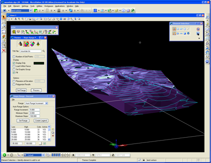
7. Themes Analysis Tools
line of sight thematic analysis of digital terrain model
- Elevation – range 620-1000, increment 20
- Slope % - range 0-100%, increment 5 (open slopepercent.rng
file)
- Aspect – open aspectrange.rng file
- Drainage Tools
Watersheds (first tool)
Drainage Patterns
Downstream and upstream traces
Flow arrows diagram (arrow size 20)
Ridge Lines and Sump Lines
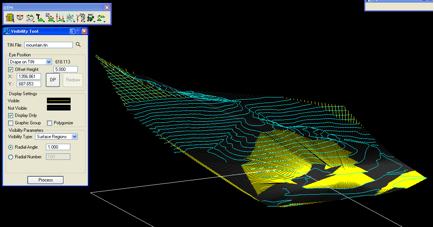
- Visibility tools (turn off contours layer)
Line of sight (visible (yellow), not visible (dark gray)
Surface points / Surface Lines / Surface
Regions
