PROJECTIONS
AND CLIP PLANES & 3D HUMAN FIGURES
Workshop
12 notes, Week of December 1, 2008
PART I: GENERATING A PDF PRINT IMAGE AND CUT SECTION
1. WITHIN MICROSTATION V8 XM: 2D Print to PDF
- Goto the
File Print Dialog Box. And using the magnifying glass icon (see arrow
below), open the driver for pdf.plt created to "print" to a pdf file rather than directly to a printer.
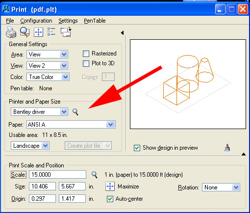
- Select the window you wish to print from in the view text box (e.g., "view2" in upper-left corner of dialog box above).
- Use the maximize option or set paper scale (e.g., 15 paper in to 1 feet in model in above example) .
- Goto File Print dialog and create the PDF file.
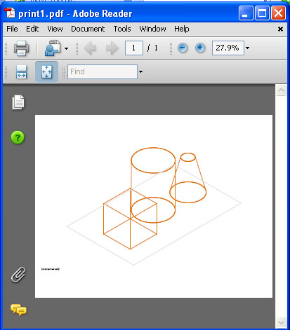
- Edit or Review in the PDF file Adobe Acrobat. Note, vector graphics holds resolution in transferred formats.
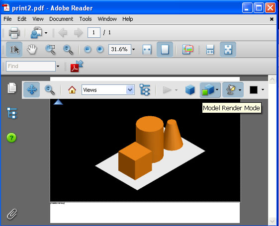
2. WITHIN MICROSTATION V8 XM: 3D Print to PDF
- Select to "on" the "Plot to 3D" dialog option within Print Dialog Box
- Note that the preview image is shaded.
- Follow remaining steps of outlined in previous example.
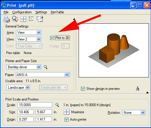
- Edit or Review the PDF file in Adobe Acrobat. Note, vector graphics holds resolution in transferred formats.
4. WITHIN MICROSTATION V8 XM: Export to UCDf format
- Create an animation for the box moving in the air as in the previous workshop on animation.
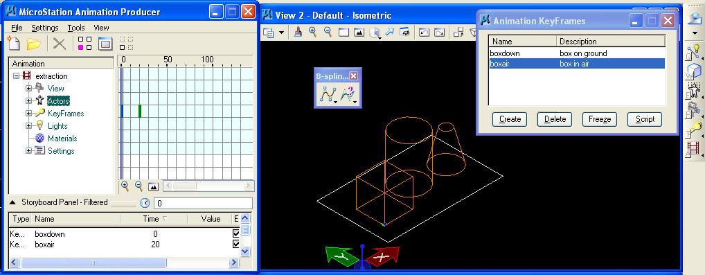
- Go to File/Export/Export UCD and save the file.
- Go to Adobe Acrobat Professional 8.1 and load in the file using the advanced editing tools.
- To load the file, use Tools/AdvancedEditing/3dtool and place a rectangle in the PDF file. First place the rectangle and then the browser opens for retrieving the file.
- Note that the animation is now viewable in the PDF file format.
4. WITHIN MICROSTATION Bentley Architecture V8 XM: Create Section through Extraction Manager
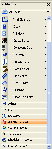
- From the Architecture tasks on the left-hand side of the screen, open the Drawing Manager dialog box.
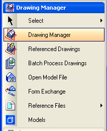
- From within the Drawing Manager tasks, select the "Drawing Manager" tool.
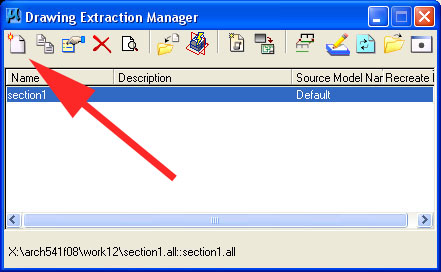
- Within the "Drawing
Extraction Manager" dialog box that follows, select the icon on the
upper left hand side, to create a "Drawing Definition"
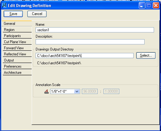
- Within
the "Edit Drawing Definition" dialog box that follows, use the drawing
definition process to specify the sectional information to
be extracted from the drawing. This dialog box has several tabs.
- Go to the
"General" tab and name the drawing (e.g, "section1" ) as well as
determine an output directory (e.g., "t:\temp\mydrawing").
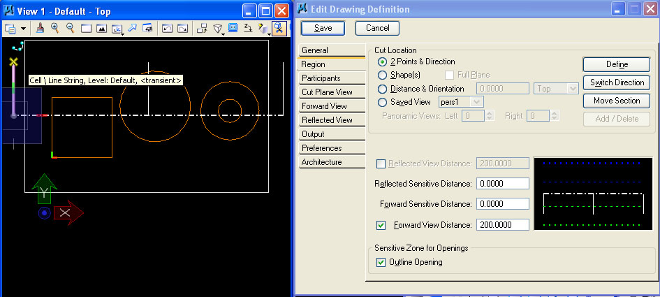
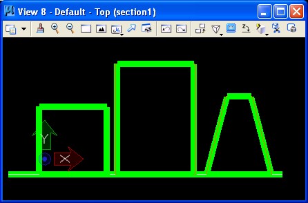
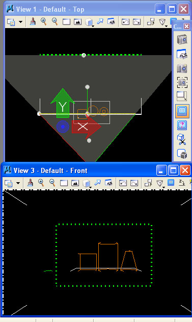
- Go to the
"region" tab", select the "Define" button for a Cut Location determined by "2 Points & Direction",
and create the section line and direction in the top view.
- Note
that "Forward View Distance" determines the visible part of model
beyond the section cut to be included in the extracted section.
- "Forward
Sensitive Distance" determines visible part of model beyond the section
cut sharing the same line graphics as the section.
- Similarly,
"Reflected View Distance" and "Reflected Sensitive Distance" (not used
in this example) reflect the part of the model that lies in front of the section cut. This is typically not shown in a section.
- Go to the
"Participants" panel and select the option to "Process Master File
Only" (we are not creating more than one extracted section drawing).
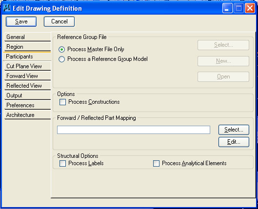
.
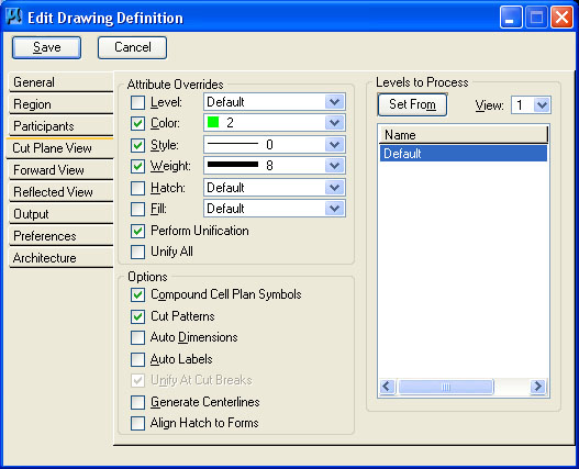
- Go to
the "Cut Plane View" tab and select line weight, color and style,
turning check boxes for each on. Note that the "Weight" is set to
8 to provide a thicker setion line.
- Go to
the "Foward View" tab and select check-box option to "Process
Forward View" (you may also choose line weight, . stule, color,
and other attributes of the graphics of the section beyond the section
cut.).
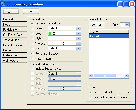
- Also insure that the "Perform Unification" check-box is on.
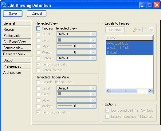
- Go to
the "Reflected View" tab if you wish to "Process Reflected View"
rcapturing geometry in front of the section (not done here or
typical).
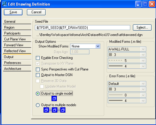
- Go to the "Output" tab and select the option to "Output to single Model" (rather than creating multiple output files).
- Leave the default options as they are in the "Preferences" and "Architecture" tabs and hit the "Save" button.
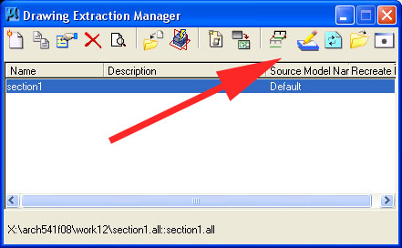
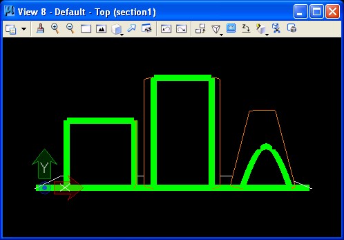
- This
results in returning to to the previous dialog box,. See the
section named "section1" now listed, and select the "Calculate
All" icon to create the section drawing (red arrow points to this
icon).
- The new
sectional drawing now appears in a separate window and can be plotted
according to the techniques of PARTII, Section 1. above. It is
also stored under the name "section1.all" in the directly named under the
"Drawings Output Directory" in the "General" panel described previously. The file extension "all" is readible within Microstation and can be opened as a separate drawing for printing.
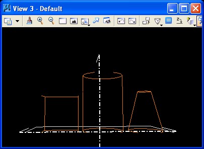
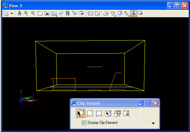
- An alternative approach is to create a 3D perspective section. This involves several more steps.
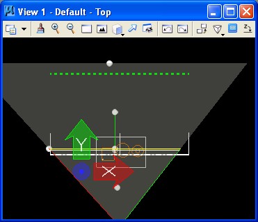
- Create
a perspective view in view 3 using the "Define Camera" tool perhaps in conjunction with the "Rotate View" tool.
- Note that
when useing the camera tool, the camera viewing envelop is evident in the top view.
- Within the same palette as
used for the tool"Define Camera". Select the "Set Display Depth"
tool (4th icon from bottom in figure below), and
1) first, select view 3 (the perspective view depicted below) as the basis for the new display depth.
2) second, go to view 1 (the top view) and place two data
points to indicate the "front" and "back" clipping planes.The "front" clipping plane will determine the section line in the extracted drawing.
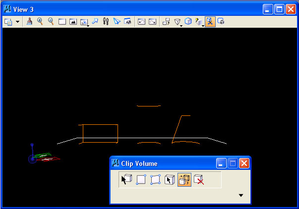
- In view
3's attribute manager (which can be retrieved from the pull-down symbol in the upper left hand corner of tje view window), turn on
the "clip front" and "clip back" options. This turns on the clipping
planes for this view.
- Next,
save the perspective view 3 in the "Utilities/Saved Views" dialog box
according to the methods we used during the last workshop.
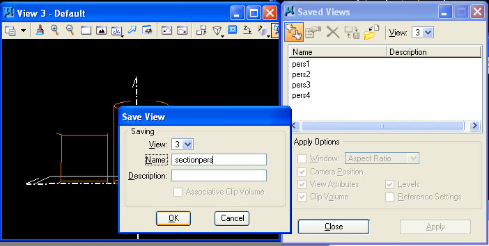
- Finally, go back to the drawing manager tool. Here, double click on the new drawing name (e.g,. "section1")
to enter back into the "Edit Drawing Definition" dialog box. Within the
"General" tab, choose the saved view option, and select the newly
created "sectionpers" view. All other paramters for this
edited drawing defintion can be retained as previously.
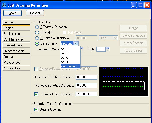
- Now go to the output tab, and turn on the "Sync Perspectives with Cut Plane Option". THIS ENSURES THAT THE "FRONT" CLIP PLANE DETERMINES THE SECTION LINE FOR THE OUTPUT DRAWING FILE.
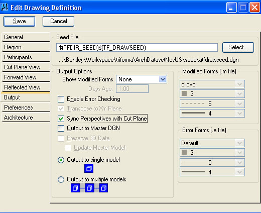
- Next, hit the "Save" button. Now we repeat steps we followed earlier when we created the first extracted drawing.
- That is, returning to the previous dialog box, select the drawing definition "section1" as listed.
- Second, select the "Calculate All" icon to create the section drawing.
- This yields the Sectional Perspective" below.
- Note that an object animation produced in this file will also be viewable in the PDF file under Adobe Acrobat 8.1. (solar animations can not be viewed).
PART II: USING THE VOLUME CLIPPING PLANE
1. CLIPPING VOLUME
- Reset the clipping planes again such that the entire model is visible, or turn them off in the "View Attributes Dialog Box".
- Also in the "view Attributes Dialog Box", turn on the volume clipping plane option.
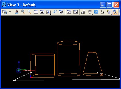
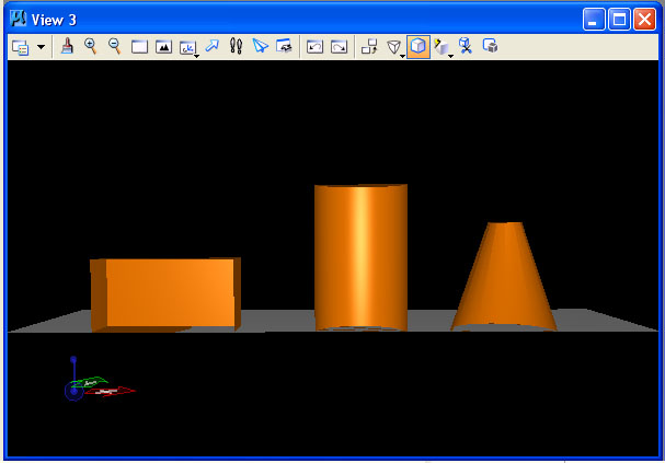
- Place a solid cube on a separate layer that partiially intersects with the model.
- In the view window
controls, select the "Clip Volume" icon (2nd from end, icon with
scissor in image below) and pick the cube.
- The model is now
clipped according to the placement of the volume. You can move the cube
to change the part of the model that is impacted. That is, all the
parts of the model outside the cube are clipped away. Only those parts
of the model inside the cube are visible.
- Within the Clip Volume, dialog box, select the second icon from the right-hand side to turn off the visibility of the clipping volume. (Alternatively, for the perspective
view, you may want to turn off the layer which holds the cube.)
- This
also ensures that the objects (e.g, the box, cylinder and truncated
cone) within the clipping volume are visible when the view
is shaded.
WE MAY ALSO ADDRESS THE FOLLOWING IN THE WORKSHOP IF TIME ALLOWS
PART III: SIMPLE EDITING IN PDF FORMAT
1. IMPORT UCD File into PDF document with Adobe Acrobat 8.1
- Open up Adobe Acrobat Professional and load a PDF file created by one of the methods above.
- Use advanced editing options to place the UCD file into the model exported above.
PART IV: ADDITIONAL VIEW OPTIONS IN PDF FILES
1. USE THE SECTIONAL TOOL on 3D PDF FILE
- Open up Adobe Acrobat Professional and load a 3D PDF file created by one of the methods above.
- Use sectional viewing tool to create cut plane and determine visibility of model.
PART V: 3D Human FIgures
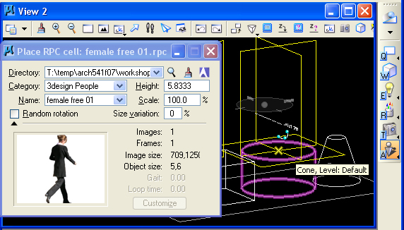
1. RPC FILES
RPC files are provided by commercial retailers who
will occasionally provide samples. These files will reorient to the
view desired. Commercial sites for obtaining such figures are: http://3dpopulate.com and http://www.archvision.com/.
The use of such figures requires the Microstation plugin available
through the visualization menu, the last sub-palette and icon indicated
below in the dialog box used to select an RPC file and place it. These
files can consist of a number of images or frames that provide varied
views syncronized with each new view orientation towards the model.
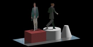
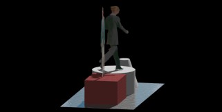
Note that two renderings from different camera
positions capture the RPC figure in 3D. However, the first figure of
the man developed through transparency mapping appears paper-thin when
viewed from some angles. For example, compare the first and second
figures below.
 |
 |
| juxtaposition of transparency map with rpc figure |
juxtaposition of transparency map with rpc figure |
See a few free samples of RPC files at
G:\Arch541-Mark-F08\Examples\people\simplerpcfiles
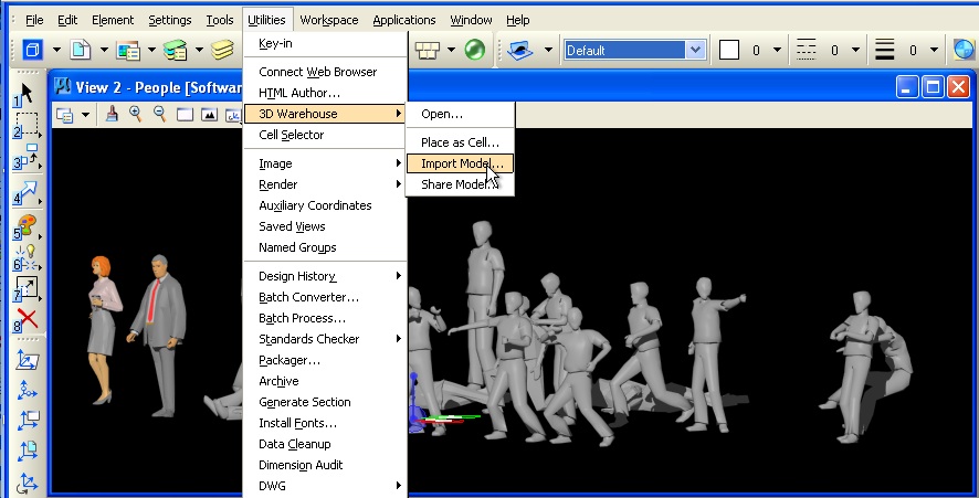
2. 3D WHAREHOUSE
Microstation's implementation of 3D Wharehouse allows
direct insertion of 2D and 3D figures(saved in the sketchup
format) into a 3D model. The dialog box under the utilties menu goes to
a web search engine for grabbing 3D and 2D human figures as well as
other objects. Some of the 3D objects may add substantial
rendering time to a model, but have the advantage of being more
easily adapted to different views of the model. Note, the option
selected under 3D Wharehouse should be "Import as Model". The 3D Wharehouse links to web site that provides many different downloadable 3D models. The example below was provided by searching under "people" and then choosing "Assorted People 3D" authored by "Distressed American. (The "Place as Cell" option would create a instance of object from a "Cell" library, something we haven't covered.)