![]()
Workshop 6 Notes, Week of October 6, 2008
ACS AND ACCUDRAW REVISITED, ARCHITECTURAL SOLIDS
1. ACS and ACCUDRAW
ACS and ACCUDRAW are two inter-related but two distinct ways of establishing construction planes. The ACS, Auxilliary Coordinate System, is set into place on a more continuous basis and can be moved into any location and orientation. ACCUDRAW, a consturction plane compass, is set into place on a more transitory basis, and can be very quickly rotated and setup in relationship to the the active ACS. The combination of both systems affords quick and contextually sensitive options to build construction planes as needed.
ACS = Auxilliary
Coordinate System. The ACS is the active construction plane, a two
dimensional plane on which you create data points.
ACCUDRAW = The Accudraw Compass. The ACCUDRAW compass is a construction
plane that is defined in relationship to the ACS. It is accssible
through a set of QUICK KEYS (e.g, "F" - front, etc.). By default, it is
co-planar with the ACS.
2. ACCUDRAW REVISITED
2. Test Accudraw by building a simple cube

2.1 preset designations (QUICK KEYS: "F" – front, or "S" – side, or "T" – top views)
Accudraw via "F" key transforms to front construction plane
Accudraw via "S" key transforms to side construction plane
2.2 determine 2d plane by any 3 points (QUICK KEYS: "RA" + pick three points)
Accudraw via "RA" key transform to 3 pt selection of construction plane
2.3 2d plane rotate 90 degrees on any axis (draw circles, arcs, etc.) (QUICK KEYS: "RX", or "RY", or "RZ")
Enter the first data point on the current Accudraw construction plan, enter the letter "O" for offset, and then use one of the following quick key combinations to rotate Accudraw around the x, y, or z axis:
Accudraw via "RX" key transforms to rotation of 90 degrees around x-axis.
Accudraw via "RY" key transforms to rotation of 90 degrees around y-axis.
Accudraw via "RZ" key transforms to rotation of 90 degrees around z-axis.
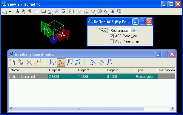
2. Menu item utilities/auxiliary coordinates for ACS options:
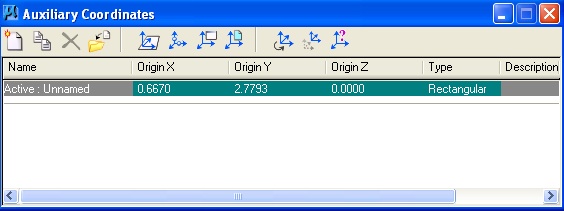
2.1a The current ACS can be saved under a named identity with the "Create new ACS icon"
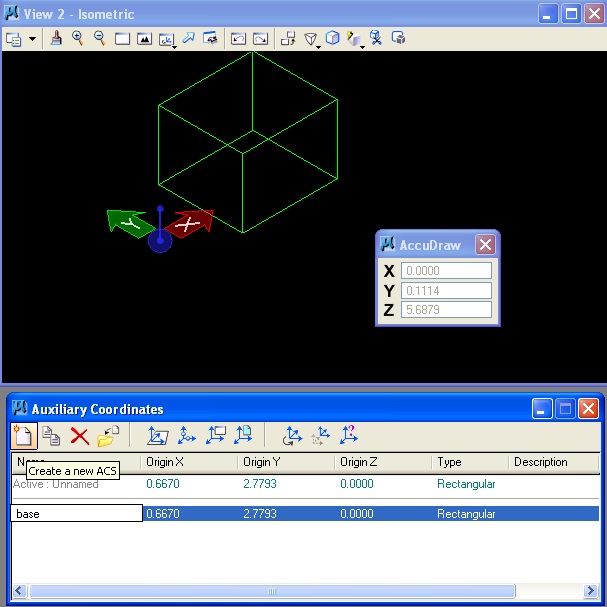
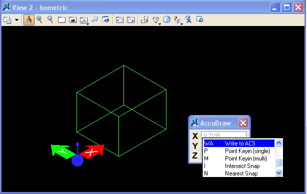
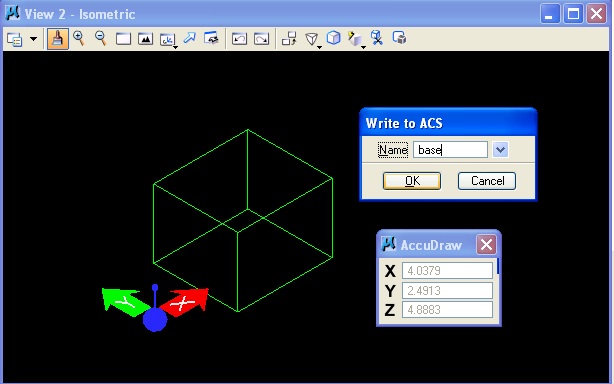
2.1b Alternatively, save “base”
(default ACS) via Accudraw by selecting Accudraw dialog box and using the quick key combination "WA"
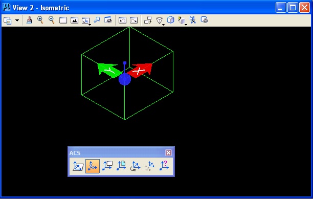
2.2 Redefine ACS (three point method). Note that the red and green arrows are rotated into the new position.
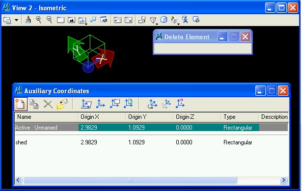
2.3 Similar to example 2.1, we can use the save the current ACS as “shed":
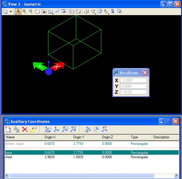
2.4 Double-clicking on “base”
restores the ACS "base":
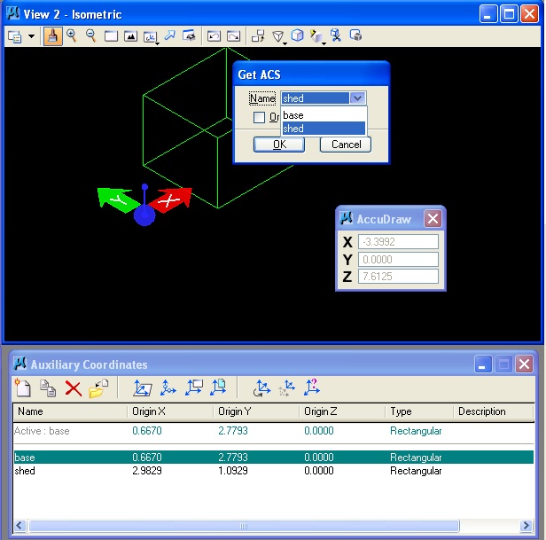
2.5 Alternatively, using Accudraw, the quick key combination "GA" restores ("gets ACS") the ACS "shed":
3. ACS via TOOLS Menu
Menu item tools/auxiliary coordinates obtains a separate dialog box thatalso allows the following ACS operations:
icon 1: define acs with element (select front rectangle of cube, fix acs to it.
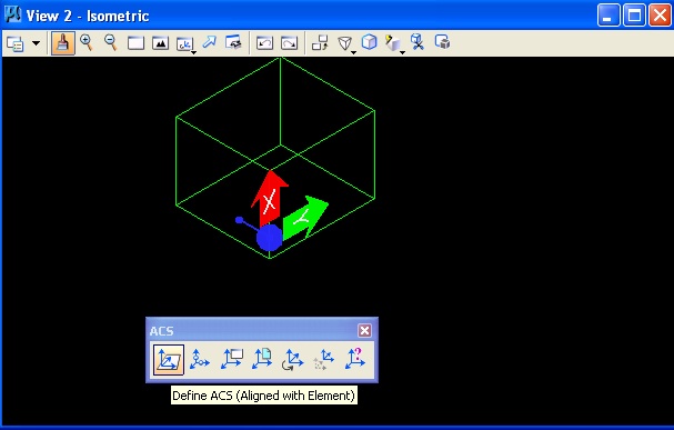
icon 2: define acs with 3 points (on face of cube)
icon 3: align acs with view
icon 4: align with attached reference file (skip)
icon 5: rotate it by value
icon 6: move it (if time)
icon 7: select ACS (similar quick key "GA”)
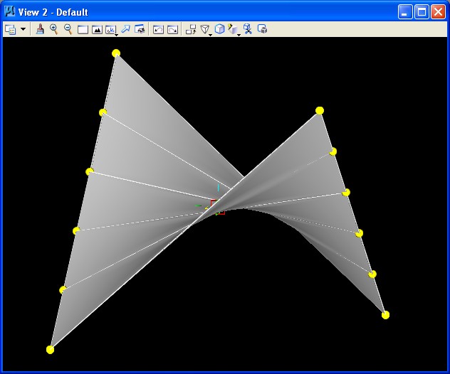
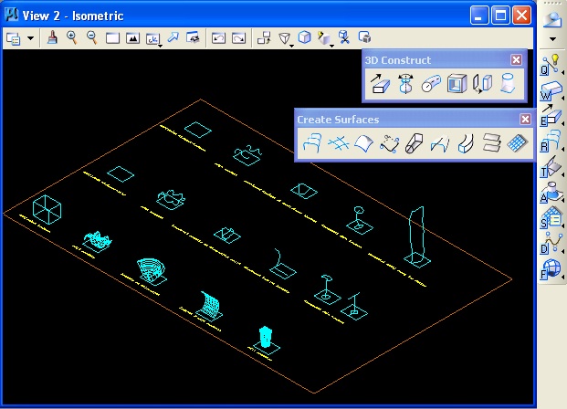
4. SURFACES
Load the file classes\Arch541-Mark-F08\Examples\surfs\surfs.dgn. In the Surface Modeling Task list, retrieve the tool boxes associated with icons labelled "E" and "R" below, and use the tool specified in each case of a surface type entity indicated in the text adjacent to each figure in the dgn file as illustrated below.
5. ARCHITECTURAL SOLIDS
Open Bentley Architecture V8 XM from the Bentley Product Suite.
Use the "Place Wall" tool to place a wall in the iso view window. Note that "Default Interior Partition" has height of 12.0 and Thickness of 1.0.
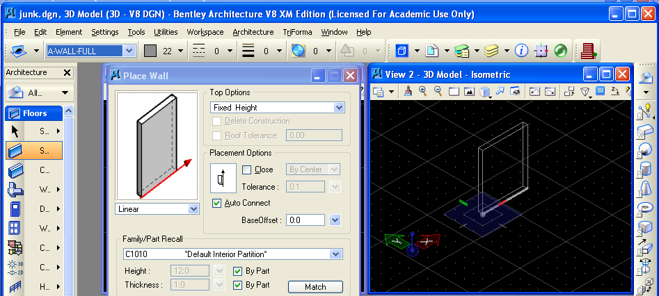
Create Two walls that cross in plan.

Copy the pair of walls five times via the "Manipulate" palette.
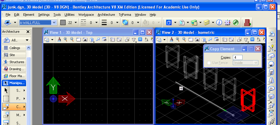
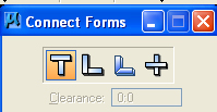
The "Connect Forms" utilities may be used to join walls in
distinct ways, including a "T" intersection, and "L" intersectiion of
where one wall is dominant, and "L" intersection with both walls form a
mitre joint, and a "X" intersection where one wall divides the other
wall into two separate walls.
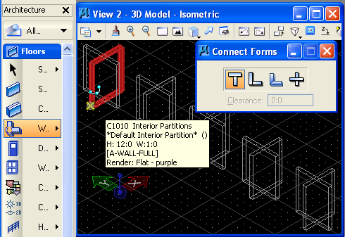
The "T" intesection (first icon) is used to joint the first pair of walls in the image below.
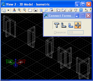
The other intersection tools are used on the next three walls to yield the following image.
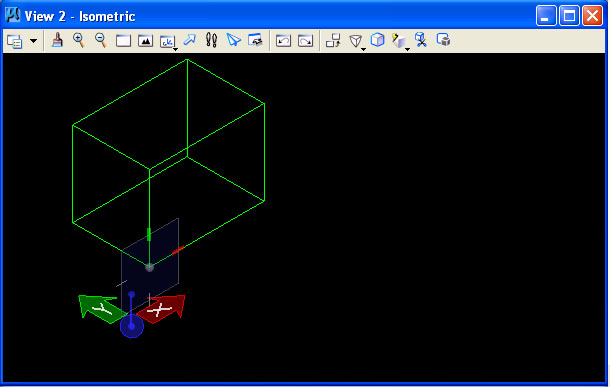
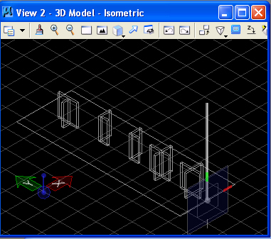
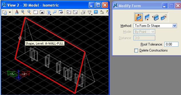
Build shed roof using line primitives and block from basic drawing palette.
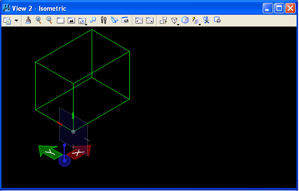
Begin by drawing a "Place Block" rectangle in the ground plan, and then, rotating Accudraw with the "F" key, place a verticle line at the mid-point of one of the sides as follows.
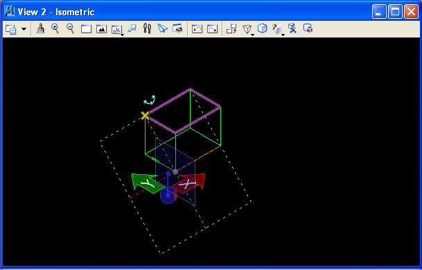
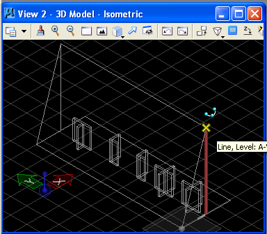
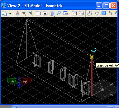
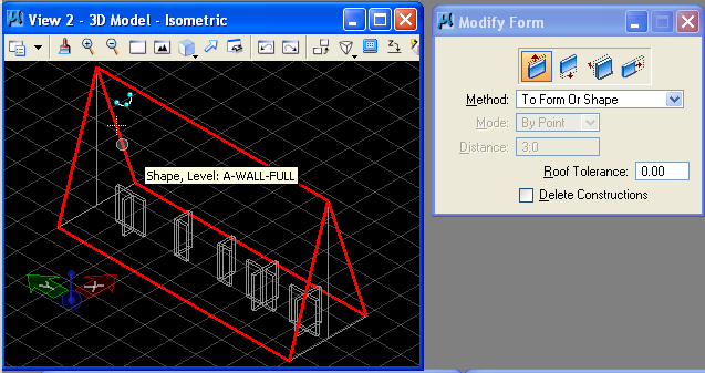
Copy the vertical line to the opposite side of the rectangle, and then draw two closed smart lines to make two sides of the shed roof.
 |
 |
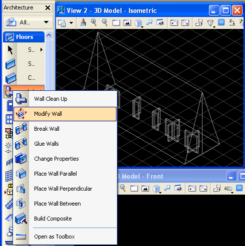
The "Modify Wall" tool is also used Project walls up to roof.
 |
 |
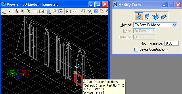
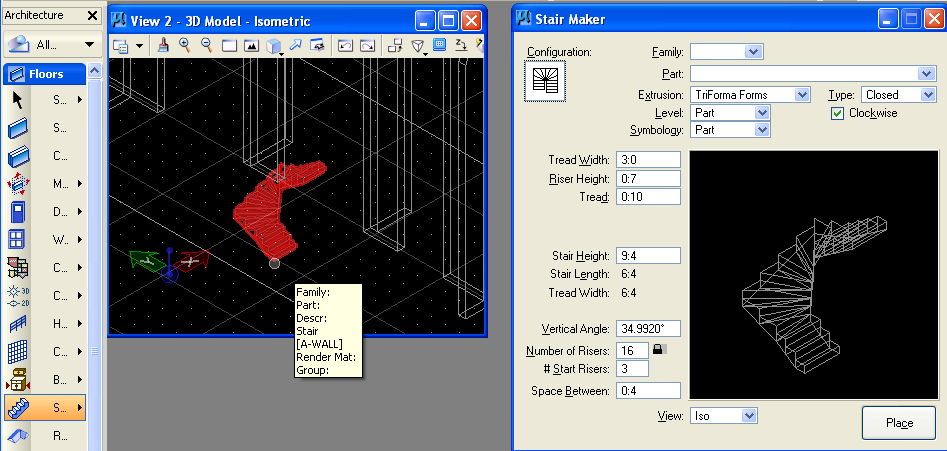
Automated tools also can be explored for drawing wall elements and stairs.
For example, the "Place Stair" tool can be used to configure and place
a stair in the model at a designated data point. This tool is also
obtained from the "Floors" palette.
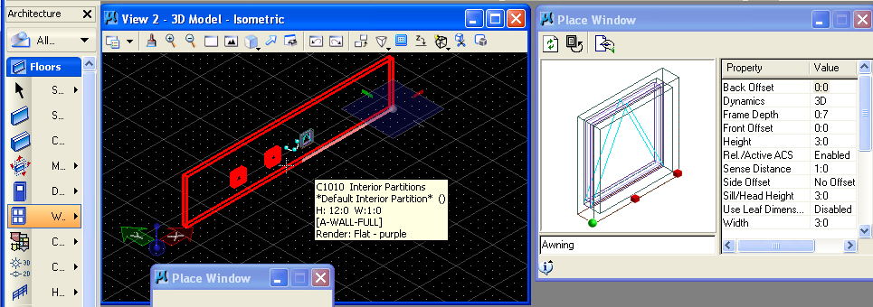
The "Place Window" tools in the same palette provides for the automated placement of pre-defined window types into walls.
6. PREVIEW OF GENERATIVE COMPONENTS
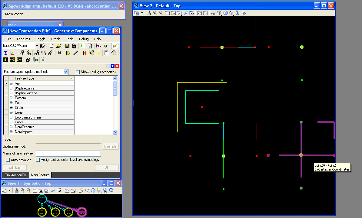
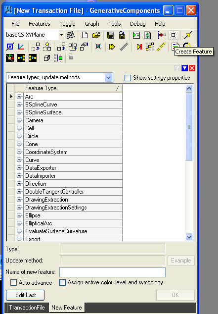
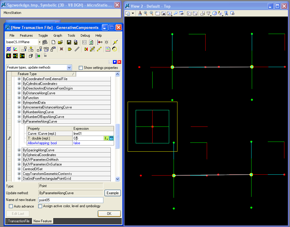
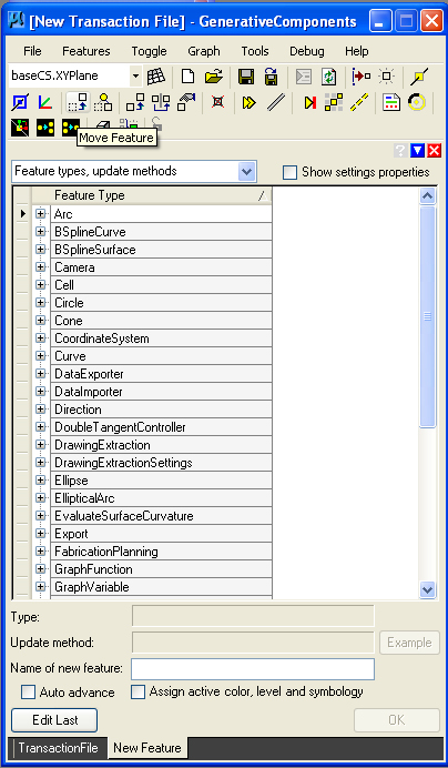
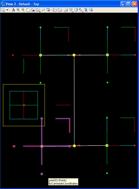
Open GenerativeComponents from the Bentley Product Suite. This is a sneak preview of technology we will explore more in earnest following the reading break. The "Transaction File" window contains a group of icon driven commands as well as so-called feature types and update methods. This example will illustrate a method of setting "constraints" with points and lines.
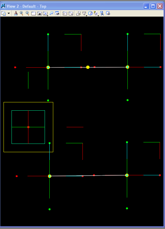
Use the "Create Point" tool (highlghted in white below) to place four points in the default plan view.
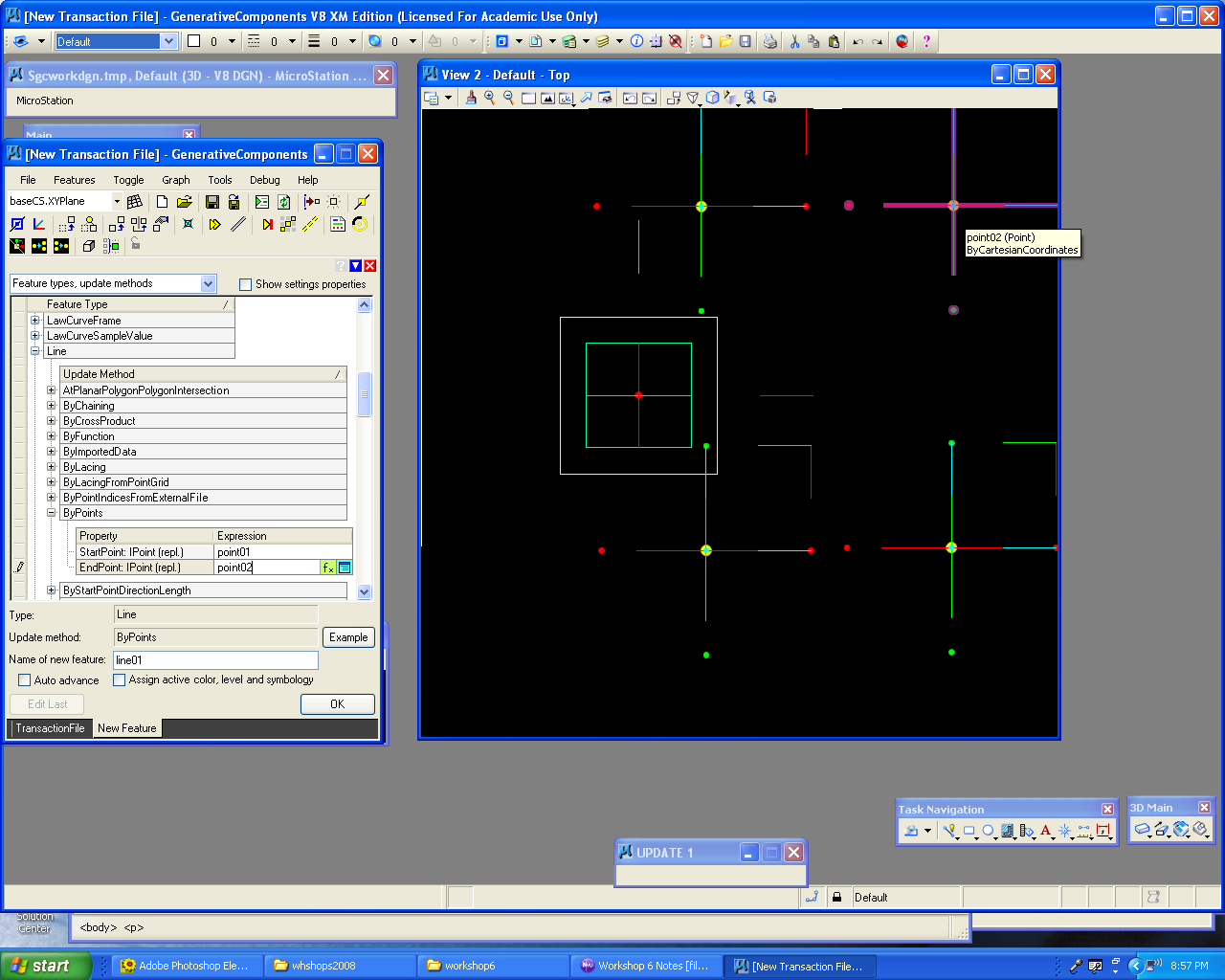
Use the feature type LIne" and ByPoints update method. Select the "StartPoint" text box, hit the "control key" and then select Point1. Similarly, select the "EndPoint" text box, hit the "control key" and then select Point2.

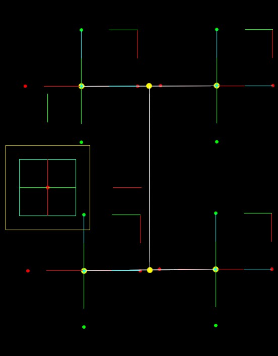
 |
 |
| Before | After |