COMPUTER AIDED ARCHITECTURAL DESIGN
Workshop 3 Notes, Week of September 14, 2009
1. ACCUDRAW
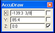
The accudraw coordinate dialog box is anchored in the lower part of the application window and echos back coordinate information:
![]()
Dragging the dialog box out of the margins of the applicaiton window will change its shape as follows. This may be more convenient for juxtaposition with the drawing elements in some situations.
Accudraw is on when you see a dialog box where you can enter distances (XY&Z) of elements that you are drawing. Your curser will also have a box around it with square crosshairs. This works with many tools (drawing lines, copying, scaling, etc.).
![]() (If Accudraw is not on, click on the green and red crosshairs symbol in
your toolbox Attribute toolbox at the top of the screen.)
(If Accudraw is not on, click on the green and red crosshairs symbol in
your toolbox Attribute toolbox at the top of the screen.)

To ensure that you are drawing at right angles, allow your line to lock into the appropriate direction. (When your line become thick). Press enter to lock into this direction. When drawing at an angle, Accudraw will adjust to this angular field. To return to the xyz orientation, press Shift and “T”.

READ ACCUDRAW HANDOUT FOR MORE DETAIL ON BASIC CONCEPTS AND TOOLS
TECHNIQUES COVERED
2. ACS PLANE LOCK AND ACS SNAP LOCK
a.Open the active locks menu, located in the bottom right corner next to the snap menu.
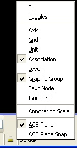
b.The ACS plane Lock forces the drawing plane to the ground plane.
c.The ACS plane snap Lock forces object snaps to attach at the ground
plane (this lock should be turned off for today's exercise).
There are a range of solid modeling options: shapes,
extrusions. This includes both standard solids in the menu "Solids
Modeling" we will explore today, and as we will see later on,
so-called feature or smart solids that allow for parametric control.
3. USING ACCUDRAW IN 3D
* Accudraw allows you to draw in Perspective View, providing you with 3 default drawing planes.
* Pressing "T" gives you Top drawing plane in x and
y, pressing "S" gives you Side drawing plane in y and z, pressing "F"
gives you Front drawing plane in x and y.
* Locking on x, y and z dimensions are possible in all three drawing planes.
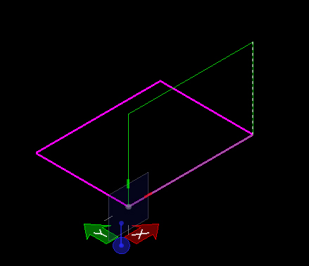
4. ROTATING ACS PLANE IN 3D
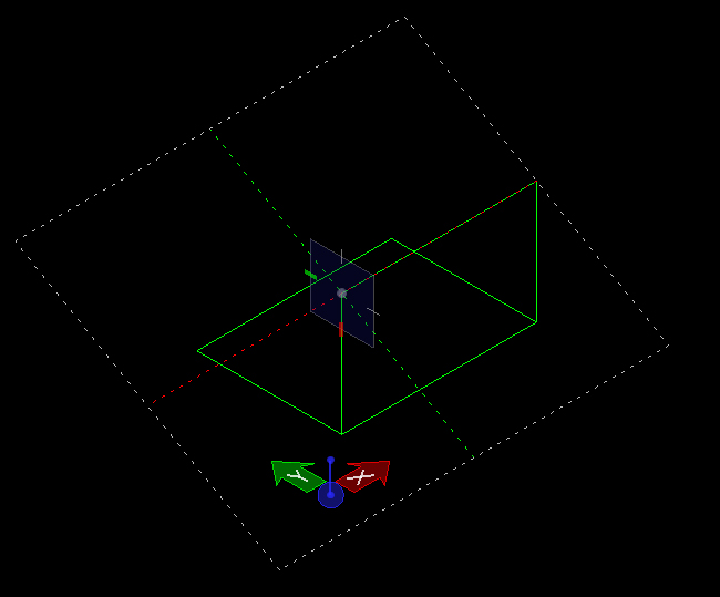
* While Accudraw is on, press "R" then "A" to activate 'Rotate ACS.'
* You can pick 3 points to set a different ACS plane in Perspective View.
* This allows you to draw on that plane, making it
easier to draw on the elements that may be rotated or slanted such as a
roof.
* Pressing "T", "S" and "F" still gives you default 3 drawing planes when ACS plane is rotated.
5. SOLID PRIMITIVES
* To bring up the solid tools go to: Task Manager > Solids Modeling > 3D primitives.
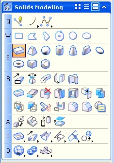
Note: These tools can be activated by specifying
their letter and number address. The solid slab tool above can be
activated by the letter and number "E1". The torus (doughnut shape) can
be actived by the letter and number "E8".
* These tools allow you to construct Slab, Sphere,
Cylinder, Cone, Torus, and Wedge by drawing a series of vectors to
describe that solid. The sequence of vectors parallels a step by step
sequence for geometry developed by Keith Critchlow (see his book
"Order in Space").
* The Slab, Cylinder, Cone, and Wedge all work in a similar fashion.
* When drawing a Sphere however, the very center of
the Sphere is placed along the ground plane. To move the Sphere up, get
into front view and use the move tool to move the Sphere up to the
ground plane by first selecting the Sphere, then typing " F" to move
Accudraw to the front orientation, and then finally move the Sphere. To
get Accudraw back onto the ground plane type " T" for top.
* For the Torus tool, it is easier to create one if you type in an explicit value for
the primary radius, secondary radius, and/or angle in the place torus
dialog box.