COMPUTER AIDED
ARCHITECTURAL DESIGN
Workshop 12 Notes,
Week of November 30, 2010
PERSPECTIVE REVISITED, DRAWING EXTRACTION MANAGER, AND RENDER FARMING
1. PERSPECTIVE REVISITED
Viewing Control, Perspective, Sections, and Saved Views
- Open a new drawing "simpleroom.dgn" in MicroStation V8i (SELECT Series 1)
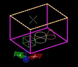
- Create a large solid box as a simple room. Put other objects - box, cylinder, cone. into it.
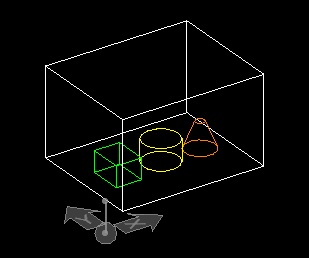
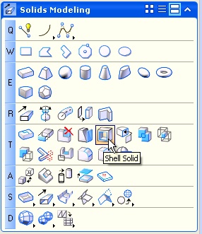
- Use the Shell Solid Tool (T5), with option to Shell Outward, choosing the top face to remove
- Place a new Slab Solid on the top, snapping to corner points to make a roof again.
- Go to the front view
- Visualization Tools (left hand side)
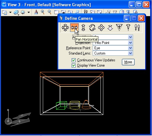
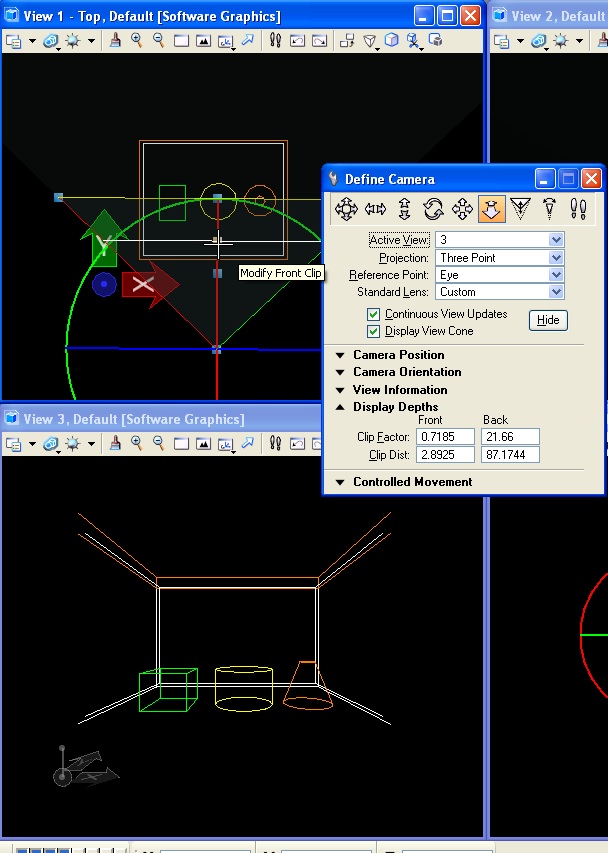
- Define Camera Tool (E2)
- Make sure Display View Cone and Continuous View Updates are checked
- Choose Pan Horizonal to Pan Left and Right (Second Tool in options) - click in the window and move the mouse to pan
- Choose Pan Vertical to Pan Up and Down - click and move mouse to pan
- Choose Dolly Forward and Back (6th option tool) - click and move mouse to move in and out
- Choose Lens View Angle (8th option tool) - click and move the mouse to zoom the camera's lens.
- Click More button. Expand Camera Position. Set Eye Pt and Target Pt Z elevation to 1 (feet). Quick way to establish proper elevation.
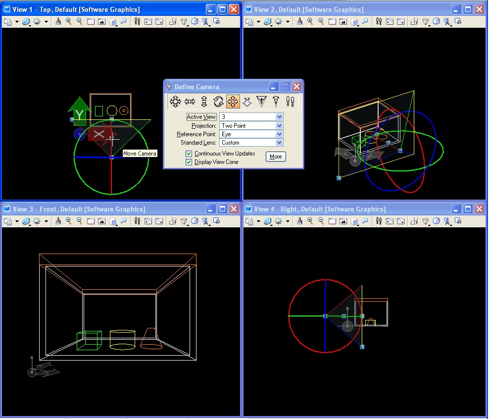
- Unmaximize your window - get back to 4 views.
- Fit view in each of the four views
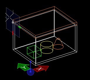
- Notice the View Cone and the white dots indicating viewing angle, eye point, and target point.
- Manipulate these points. Watch the perspective view change as a result.
- Go to View Attributes drop down (top left of perspective window)
- Check Clip Front and Clip Back
- Within the Define Camera tool, under Display Depths, adjust the "Front Clip Factor"
until the the model begins to clip away in the front view.
- A positive value of at least 0.2 under the front clip factor will begin to establish this clipping plane inside the viewing envelope.
- Note that the factor value is a percentage distance from the view point to the opposite end of the viewing cone.
- Look in perspective view now and you will see part of the model cropped away.
- Look in the view cone in the plan view - there is a new line and control dot representing the section plane. Move it and watch the section cut move in the perspective window.
- Set it to a location that you like
- Go to the Utilities/Saved Views menu.
- Choose the Two-Hands icon to capture your view.
- Give it a name "sectionsperspective" in the settings dialog that appears, then click in the perspective window to save it. A balloon will pop up indicating it is saved.
- Rotate and zoom to a different view.
- Go back to the Saved Views drop down and double click the named view you just saved. Your view will return to this state.
2. DRAWING EXTRACTION MANAGER
- Close MicroStation.
- Open Bentley Architecture V8i (SELECT Series 1) (from Bentley Building subfolder of the Bentley Program Group in the Start Menu)
- Find and Open the file you were just in
- Fit view in all four views.
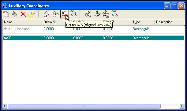
- Turn of the ACS Plane and ACS Plane Snap locks
- Use the Auxiliary Coordinate Dialog Box to Define the ACS Aligned with the front view # 2
- Go to Main Menu at top of screen, find the menu Project Management > Drawing Manager > Drawing Manager
- In the Drawing Manager window, choose the New (Create a Drawing Definition) icon (first icon)
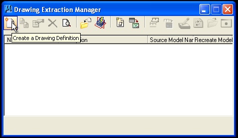
- Type in a name for this drawing - call it Plan 1
- Click on Region tab - choose 2 Points & Direction and click Define
- In your front elevation view (usually lower left), draw a line with two data points at an appropriate "plan" elevation level. This will be the section cut line of the plan.
- Choose a direction (up or down) to view. For a plan, this should be down: place a data point below the elevation level to determine the direction.
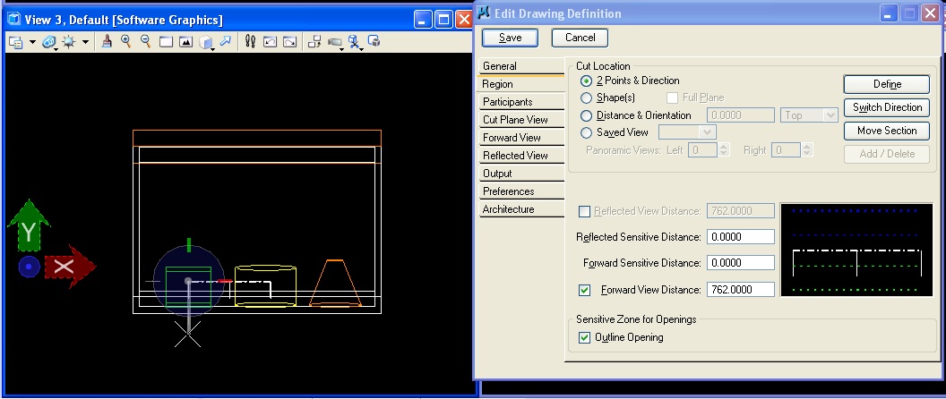
- Go to the Cut Plane View tab - make the Weight of the cut plane a weight of 2 (heavier line weight for what is cut in section) and turn the check-box for the weight to "on"
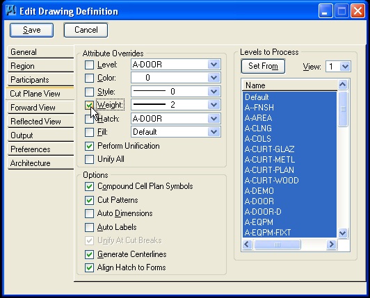
- Go to Forward View tab - notice that it is set to Process a Forward View (interior elevation beyond the cut plane)
- Go to Reflected View tab - Uncheck this option unless you want the reflected view
- Go to Output tab - Choose Output to Single Model
- Click SAVE at the top of the window. This saves your drawing definition
- Do the same sequence for a Section view, Defining the section with 2 Points & Direction, adjusting the other tabs as as before, and using the plan window (top left) to place it.

- Do the same for a Saved Perspective View, loading the section perspective view saved earlier, , and then adjusting the other drawing definition tabs as before
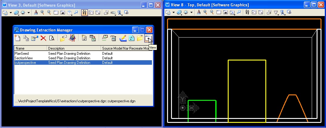
- The only difference here is to use Saved View instead of 2 Points & Direction to define the Region (see image below), then select the saved view you want to use
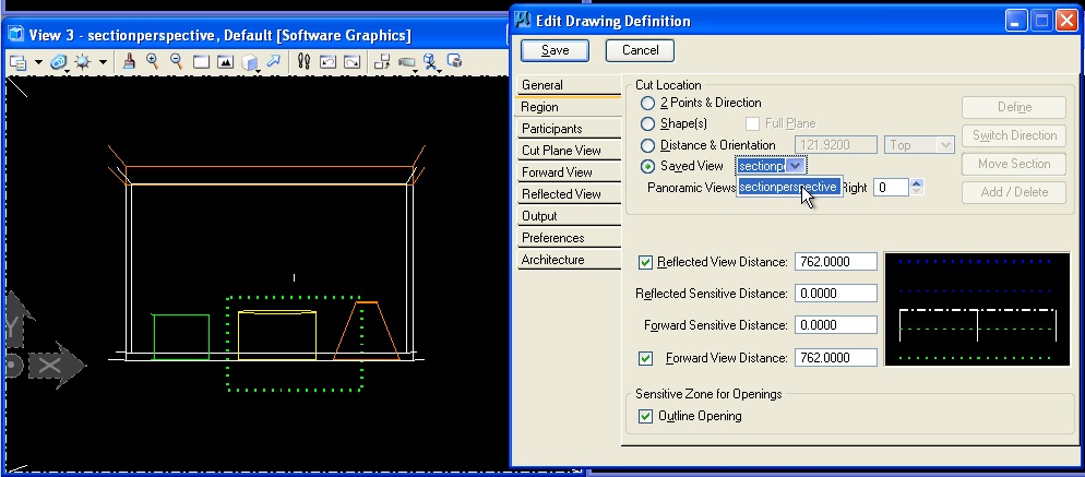
- Then go to Output tab and select the checkbox to " Perspectives with Cut Plane"
- Click SAVE
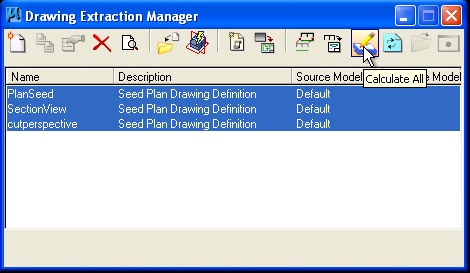
- Now back in the main Drawing Extraction Manager Window, select each of the defined drawings in the list (use CTRL to select more than one of them), and then click Calculate (blue paper with pencil icon) to calculate all of the drawings.
- When done, choose one of them and click View (far right icon) to see the drawing in preview. Note sections lines are highlighted in greater line-weight.
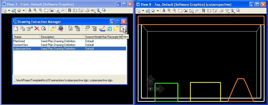
- or Open (second from right) to open the extracted drawing as it's own file for editing.
- Go back to main Model File via Top Menu > Project Management > Drawing Manager > Open Model File
- Modify your model -> move things around, or resize, or add more objects.
- Go back to the Drawing Manger window.
- Click Calculate again, then open an extracted drawing. The extracted drawing has been updated to reflect your changes (resized cylinder in the section below).
3. RENDER FARMING
Rendering Farming can be used to take advantage of a concentrated cluster of CPUs dedicated to rendering.However, during peak periods of usage, such as during final design studio charlette, the limited number of CPUs may be exploited by a potentially large number of users thus dividing up their effectiveness. Thus, during peak periods, the current level of technology may be less effective than rendering images on one's personal computer. In the near future, a larger grid computing cluster that is currently being tested may help to ensure the effectiveness of this technology for a large simultaneous cohort of users. The luxology render window contains an icon for distributed rendering that is second from the upper-left hand corner. Details for render farming with Microstaion are described in the handout MicrostationDistributedRendering.pdf.
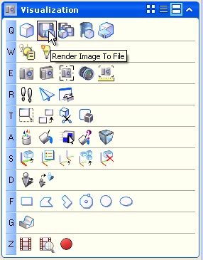
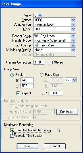
In addition, a key advantage to render farming is that Microstation files can be placed in a shared public folder, such as on "scantemp", "projects", or "classes", the rendering software launched, and Microstation exited while the rendering is in progress. The luxology rendering window can not be used directly for this. Rather, the tool needed for rendering in this particular way is located in the Visualization Task. Select the Render Image to File "Q2" tool and in the dialog box that follows, choose the option for distributed rendering. Ensure that both the file to be saved as well as the dgn file are both located on one of the public folders.