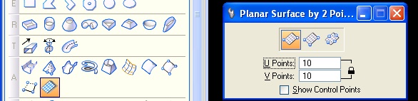
- Planar Surface by Points - with UV 10 and 10 (A 10)
COMPUTER AIDED
ARCHITECTURAL DESIGN
Workshop 6 Notes,
Week of
October 4, 2010
SURFACE EDITING, PERSPECTIVE CONTROL AND CLIPPING PLANES
1. Surface Editing
Surface Modeling Toolset
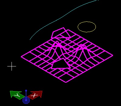
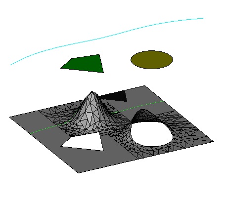
- Planar Surface by Points - with UV 10 and 10 (A 10)
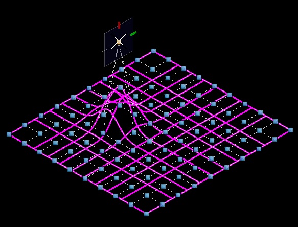
- Grab handles with selection tool (arrow tool), elevate points to make wavy surface
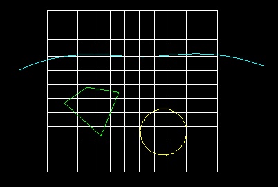
- change color -> Draw Polygon shape on top of the surface
- change color -> Draw Circle on top of the surface
- change color -> Draw bSpline curve on top of the surface
- grab all three and Move them in the front construction plane (F CP) to hover above the surface.
- Grab whole set - make a Copy to the side
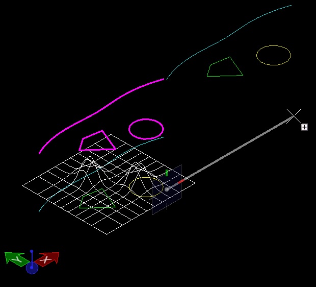
- Optionally, use plan view for ease of orientation
- Zoom to first surface
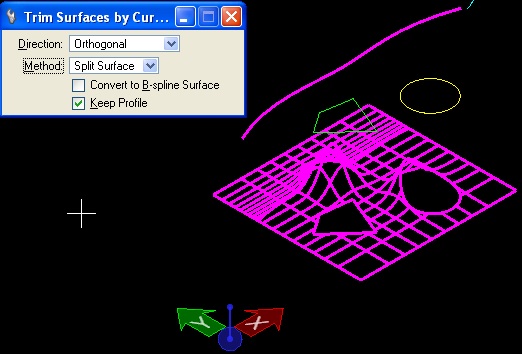
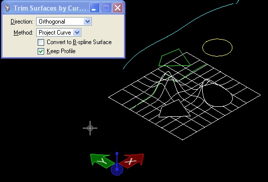
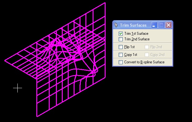
- Trim Surfaces by Curves tool (S2)
- Make sure Keep Profile is checked.
- Option Trim Surfaces / Orthogonal
- Select Surface, select polygon.
- Do again with circle
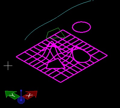
- Do again with bSpline
- note which side you grab matters to which one you keep
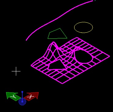
- Same Tool (Ctrl -Z to undo previous cut)
- Change settings to Split Surface - do again
- Change to Project Curve - do again (see green bspline projected onto surface below).
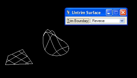
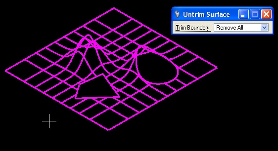
- Go to copied polygon, circle and bsplne, copy surface and use untrim-surface tool (S3) with "Remove All" option.
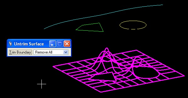
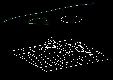
- Surface trimmed holes are removed
-Select the Mesh From Element toos (Z1) and apply it to the restore surface.
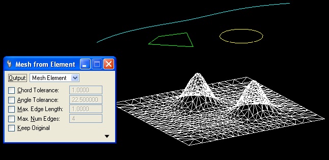
- Go back to Trim Surfaces tool, with Trim Surface method - perform the same operations the meshed surface.Same result .
(( SHOW ONLY ))
(Rotate/Copy mesh surface and bSpline up to a standing wall, use Trim Tool)
- We're doing these on top-down surfaces, but they work just as well standing up.
Make a Copy of one of the original surfaces
- Untrim Surface tool (S3)
- Select Reverse as method and see what happens.
- Undo and Select Remove All as method, to remove all cuts and get back to original uncut surface.
- Rotate surface upon itself using Front Constuction Plane and Active Angle method at 90 degrees, Making a Copy
now we have two intersecting surfaces.
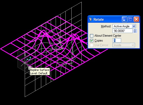
- Use Trim Surfaces (S1) tool. Select both Trim 1st and Trim 2nd Surface options. Select the pieces of each surface you want to keep.
Planar Slice Tool (F4) - extract sections and profiles of geometry
- Copy and Untrim the surface again (or just undo a few times)
- Go to the Side View orientation
- Draw a line over and bypassing the surface.
- Copy the line several times to make a bunch of them at equal intervals. (use number of copies option on copy tool)
- Now using the selection tool, grab all of the lines
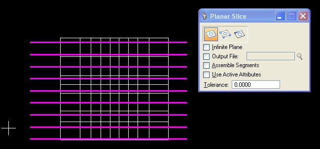
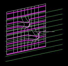
- Use the Planar Slice tool (F4) with the First option icon (Slice by Element), and confirm.
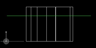
- Rotate around to see the sliced section lines. You might need to delete the surface or change layers to see it clearer.
(( Show only ))
This can also be done with planar, non-planar and non-linear elements
- draw a polyline at various right angles across the surface. Extrude in both directions to get an upright plane.
- use the Planar Slice tool to generate the section along that edge.
- Do the same with a series of bSpline curve extrusions.
2. Viewing Control, Perspective
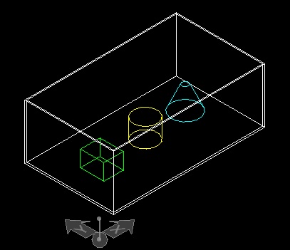
- In Solids Modeling tools, create a still-life of Platonic objects
- Create a large solid box as a simple room. Put other objects - pyramids, ellipsoids, spheres, polyhedra, etc. into it.
- Use the Shell Solid Tool (T5), with option to Shell Outward, choosing the top face to remove.
- Place a new Slab Solid on the top, snapping to corner points to make a roof again.
- Go to the front view
- Stretch into a perspective (quick) - you already know how to do this.
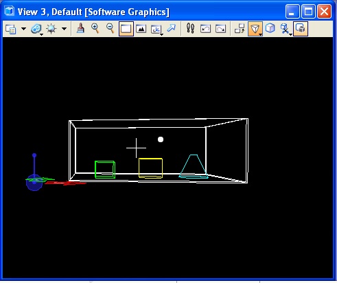
- Now change the camera lens. Normal - Telephoto - Extra Wide - Dynamic
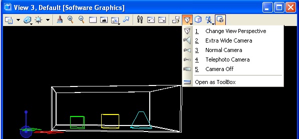
- Return to Normal Camera
- Visualization Tools (left hand side)
- Define Camera Tool (E2)
- Make sure Display View Cone and Continuous View Updates are checked
- Choose Pan Left and Right (Second Tool in options) - click in the window and move the mouse to pan
- Choose Pan Up and Down - click and move mouse to pan
- Choose Dolly Forward and Back (6th option tool) - click and move mouse to move in and out
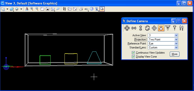
- Choose Lens View Angle (8th option tool) - click and move the mouse to zoom the camera's lens.
- Click More button. Expand Camera Position. Set Eye Pt and Target Pt Z elevation to 5 (feet). Quick way to establish proper elevation
- Unmaximize your window - get back to 4 views.
- Fit view in each of the four views
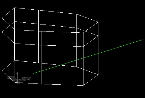
- Notice the View Cone and the white dots indicating viewing angle, eye point, and target point.
- Manipulate these points. Watch the perspective view change as a result.
3. Clipping Plane and Saved Views
- Go to View Attributes drop down (top left of perspective window)
- Check Clip Front and Clip Back
- Look in perspective view now and you will see part of the model cropped away.
- Look in the viwe cone - there is a new line and control dot representing the section plane. Move it and watch the section cut move in the perspective window.
- Set it to a location that you like
- Find the Saved Views drop down from the top tool bar (mountain in a camera lens).
- Choose the Two-Hands icon to capture your view.
- Give it a name in the settings dialog that appears, then click in the perspective window to save it. A balloon will pop up indicating it is saved.
- Rotate and zoom to a different view.
- Go back to the Saved Views drop down and double click the named view you just saved. Your view will return to this state.