COMPUTER AIDED ARCHITECTURAL DESIGN
Workshop 5 Notes,
Week of October 3, 2011
DIGITAL
TERRAIN MODELING PART I
Note:
This
workshop
focused on a a few introductory digital terrain modeling methods. The primary method of more
immediate practical value is captured under item #1 below as applied to
Carr's Hill. We will advanced to other
methods later on involving external "tin" and "lat"
files the offer more complete analysis options that you might undertake
in studio.
1. Terrain
Modeling (expeditious method)
dgn file
of
Carr’s Hill
- Open
SiteCarrsHill.dgn
from the classes folder.
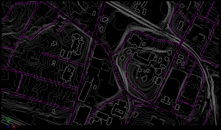
- Rotate
to view 3D survey data – typical of GIS
data received from municipality
- Create
and make active a new layer titled "simpleTIN".
- In a few weeks time we will explore other possibilies with layers to capture an advancedTin and latticed mesh terrain model.
- Turn
on predefined contour layers named " INDEX" and" INTERMED", and turn
off all
other layers except for the active layer simpleTIN.
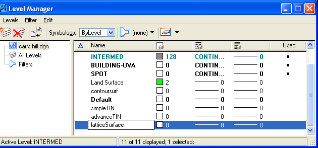
create levels
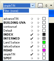
make simpleTIN the active level
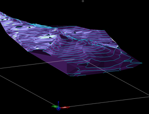
- Select "Mesh from Contour Tool" from
pull out toolbox from icon in lower left-hand side of Surfaces palette.
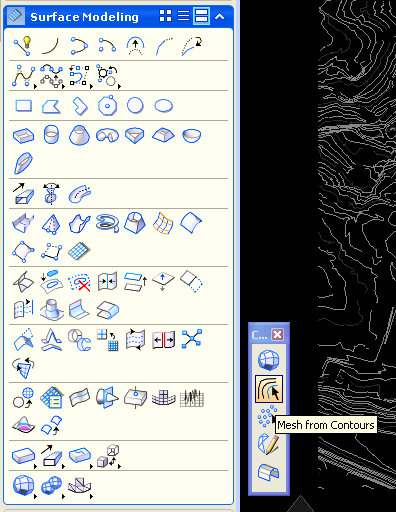
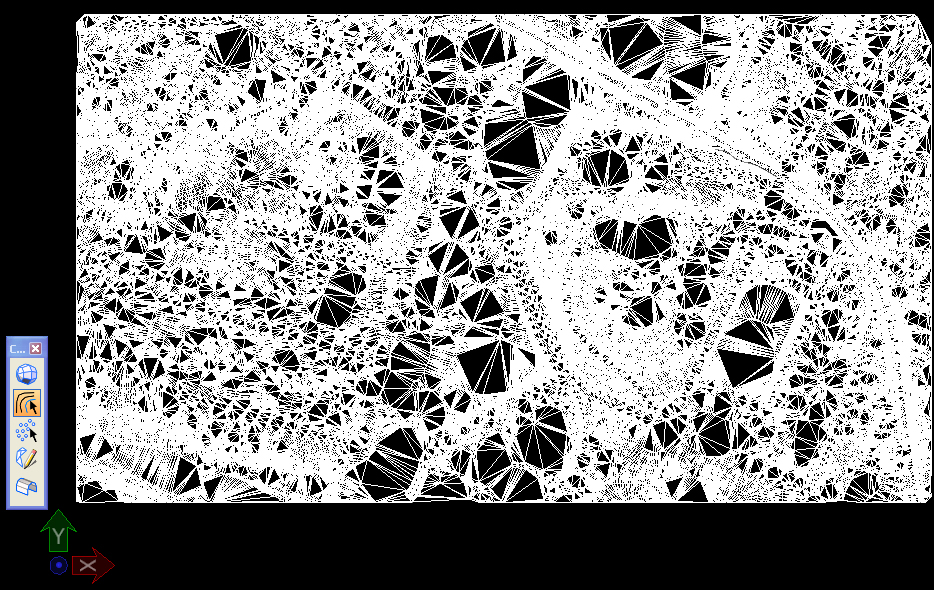
- Select the tool and then hold down
continuously the
left mouse button to draw an invisible box around the contour lines on
the screen. Move the mouse off the contour lines, and hit the left
mouse button to accept the contour lines and generate a
triangulated mesh.
2. Terrain
from Image File:
New CAD File (Due to a temporary configuration issue, it is necessary to use the older version of Microstation V8i for this exercise).
- The Image
underlay file topo2.jpg that has been placed in in classes is a scanned
in image of a site plan with topological lines. –
- Note the scale of topo2.jpg is
1”=300’ and the actual dimensions of the scanned
in image are 7.5 x 12
inches in paper size
- Close
the image
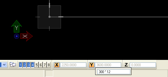
- Inside Microstation, draw
rectangle at an appropriate size for attaching topographic image
above, using the Addudraw popup calculator in the coordinate text
boxes for "X" and "Y". After entering a lower left-hand data point,
then for the "X" coordinate enter "=" and then "300 * 7.5", and for the
"Y"coordinate enter "=" and then "300 * 12.0".
- Fit
View
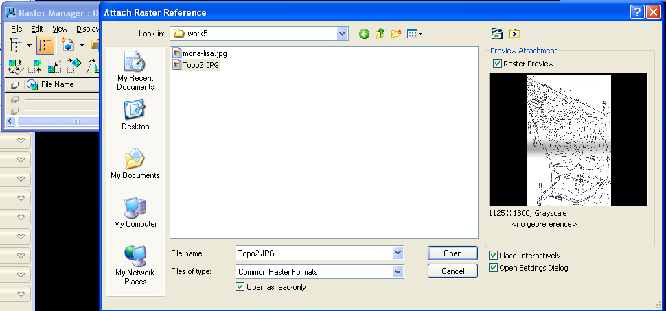
- Use the File Menu/Raster Manager
dialog box, and interactively load the file topo2.jpg and use the
"Place Interactively" feature so that it is
scaled to the rectangle created in step 4.
- Use the Utilities>KeyIn dialog
box, to enter "MDL
Load Civtools" (tool available for download
from School of Architecture website)
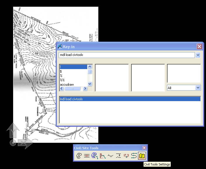
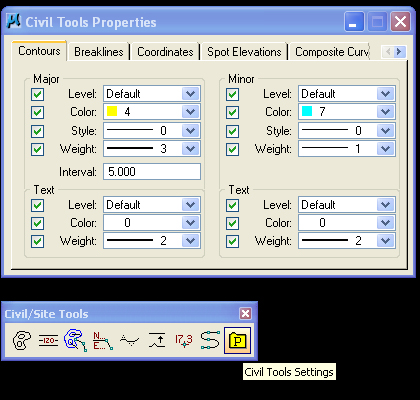
- Within the Civtools dialog box:
- [P]
tools – parameters – set
major/minor interval and colors/layers
- Choose
first tool – place contours - establish elevation level for each
contour line and trace over the scanned in image using the curve tool
option, and setting "planar" check box to on.
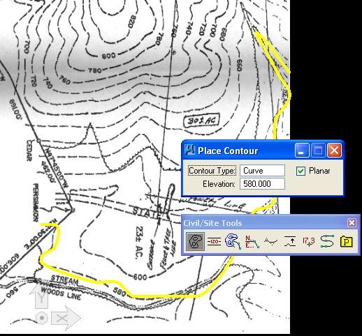
- Note: you need to explicitly enter
in new elevation values into the Place Contour dialog box for each
contour line, such as the elevation 580' above.
- Set
current elevation – 600 – and draw
Keep going up the mountain.
- Once the contours have been
created, you may use either Surface tool "Mesh from Contours" tool to build a terrain file. (Here is a version of
the above file with contour lines (blue) re-loaded and normalized from
the external TIN file.