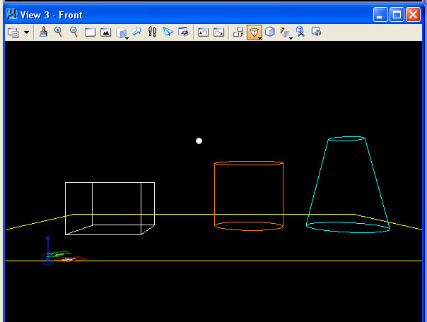
2. Go to the front elevation view.
3. Select perspective too from view 3 window (quick method tool selected in window below).
COMPUTER AIDED
ARCHITECTURAL DESIGN
Workshop 10 Notes,
Week of November 14, 2011
Animation, Demonstration of Generative Component Surfaces
1. Animation
Part I. Animation WIth the Animation Producer Dialog Box
Animating Views and Sun
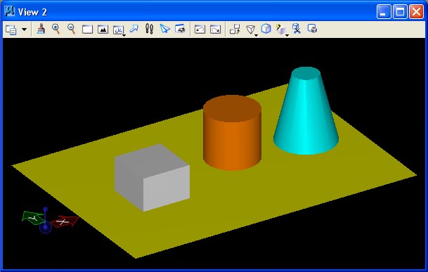
1. Construct a simple model with a surface
plane and three simple solid objects (slab, sphere and cone – from Solids palette)
in iso view.
2. Go to the front elevation view.
3. Select perspective too from view 3 window (quick method tool selected in window below).
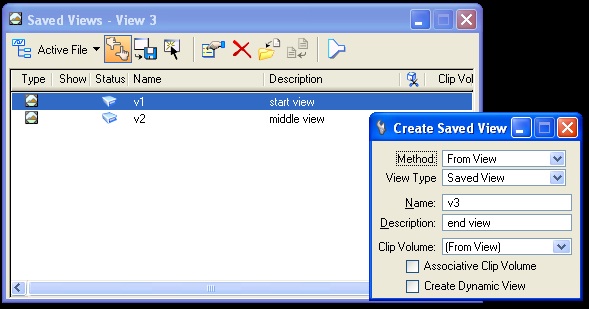
4. Begin to save a series of views that establish a sequence of movement towards the three objects. Keep in mind that as you set up your views (keyframes)
you will be able to apply different velocity descriptors: "constant", "accelerate",
"deaccelerate" as a way to control the seed of movement between views. We will will use "constant" velocity further below. Go to: utilities/saved views, and save at least three successive views of the model.
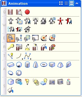
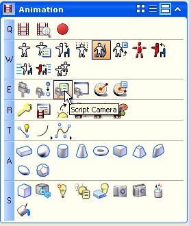
5. Once you have saved the views you can begin to assemble the views into your animation sequence. Go to: Task List Animation. Select the animation producer icon highlighed below (Q1).
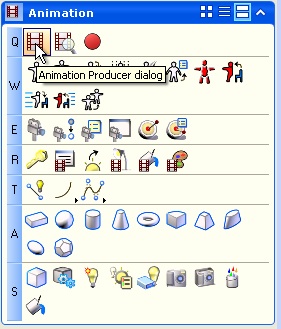
and then, from the "Animation Producer" dialog box, open "tools/saved views":
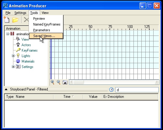
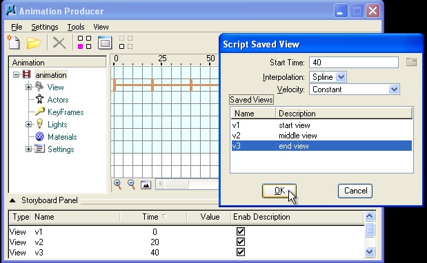
as depicted below, in the Script Saved View dialog box::
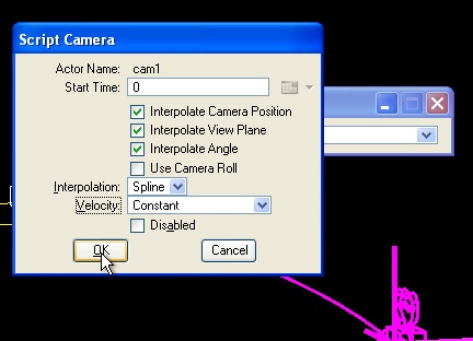
double click on v1 and enter: Start Time "0", Interpolation "spline", Velocity "Constant"
double click on v2 and enter: Start Time "20", Interpolation "spline", Velocity "Constant"
double click on v3 and enter: Start Time "40", Interpolation "spline", Velocity "Constant"
.... and so on if there are any additional saved views you wish to incoporate into the animation sequence.
Note that Interpolation “Spline” refers to the movement between your views as key framed locations for the camera in the model space. Velocity “Constant” refers to
the velocity that the animation moves between the given views.
Next, create a subdirectory, such as one named "movieframes", for storing individual animation frames on your local hard drive (a folder).
6. Go to Visualizationm task, select the W1 lighting manager tool, to setup global lights and turn on the sunlight. Check also that the Ambient Light and Flashlight are set to appropriate intensites and that the color of all the lights is white.

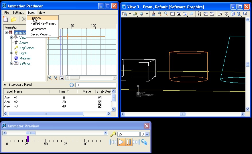
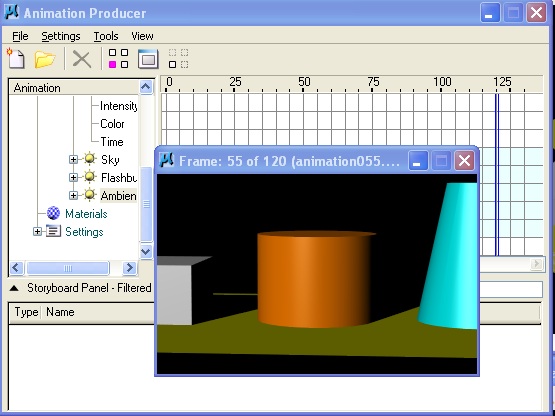
6. To preview your movie from within the Animation Producer dialog box. goto Tools/ Preview, and play through the results for view 3.
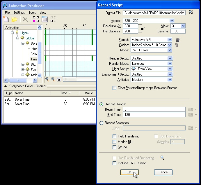
7. Next, return to Animation Producer dialog. Go to File/Record Script in order to record animation as a series of single single jpg files with the following settings:
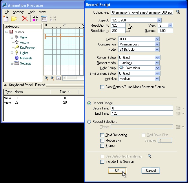
Select the "OK" button, and animation will render with a visible echo back to the view screen.
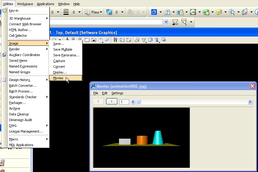
8. To play your movie: go to the menu utilities/image/movie, and then with the "Movies" dialog, box, go to "Load" and find the image file "testani000.jpg" under whatever folder you have created in step 5 above.
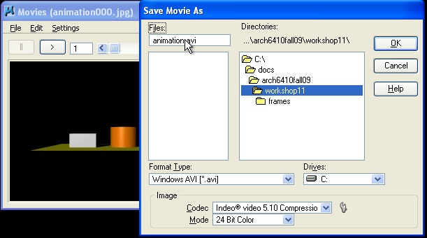
9. From the same Movie dialog box, you can then use file "Save As" option to save the completed movie to single file ( avi etc.), such as
" animation.avi".
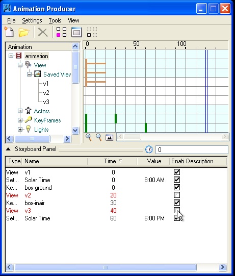
10 . In order to simulate the pathway of light throughout the course of a day, in the Animation Producer dialog box/animation palette go to:
Lights/Global/Solar/Time, and right-click on the word "Time" to select the "script" option. This results in the "Animate Settings" dialog box.
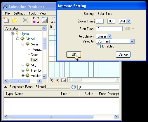
In the "Animate Settings" dialog box, create the following settings for two different times:
11. As before, record animation in the jpg format with the following setttings:
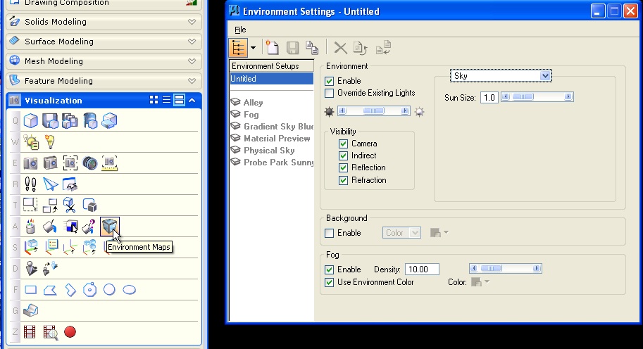
12. Use the "Environment Maps" (A5) tool to create background environmental conditions for the "Untitled" setup, such as for fog as depicted with the settings below. Note that the value for "Density" at 10.0 would represent a fairly thick fog. Density is a setting that can be animated through the animation producer dialog box, similar to solar time.
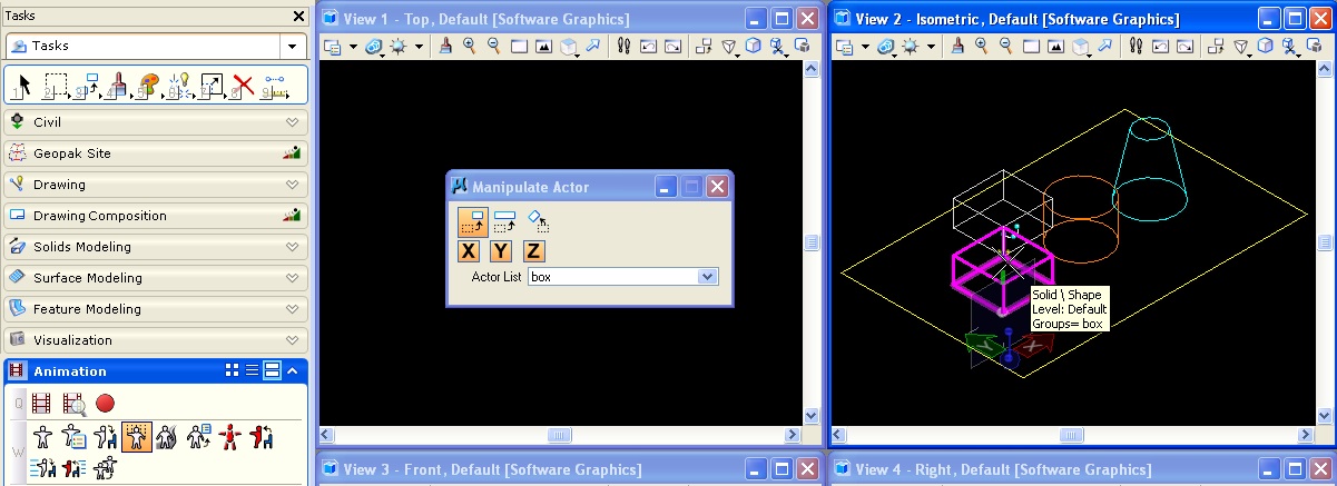
PART 2. Animating Objects
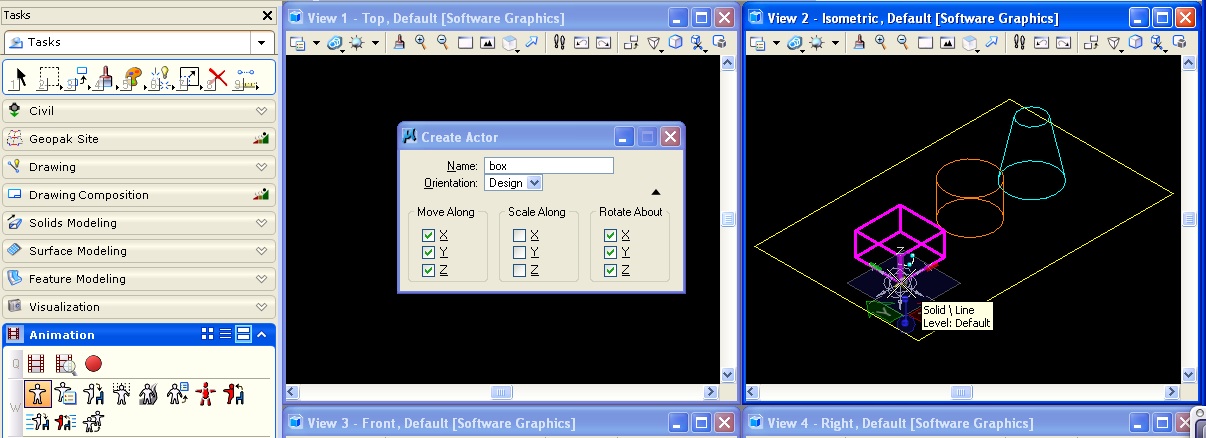
1. Making an actor
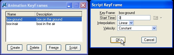
2. Now keyframe the actor via Animation Producer Dialog box:
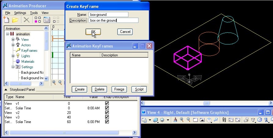
3. Now script the keyframes at 0 and 60
4.Record the animation as jpg or avi as before.
5. You can then make and select more actors (animate more objects) if so desired.
6. Using algebraic descriptors
6.1 Go to the Tools/parameters
in animation
Producer
Dialog box, and create a variable
From the Animation Producer dialog box's Tools menu, choose "Parameters" .
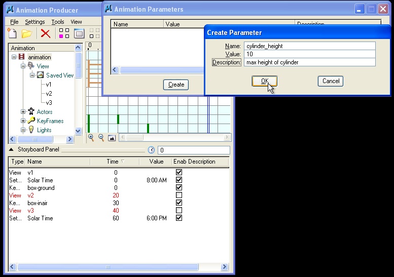
| The Animation Parameters dialog box opens |
6.2. Now, go to the Script actor tool (W6), and select the "box".
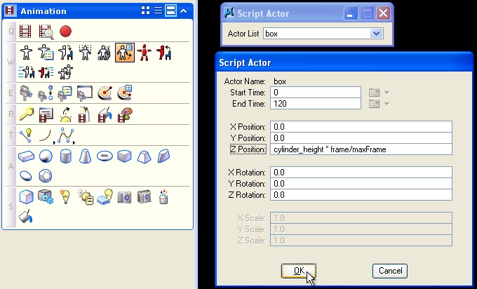
In the blank field for "Z Position" , enter "cylinder_height * frame/maxFrame" and select the OK button.
6.3 Record animation using methods already expored.
res. 320 x 200
raytrace – antialias
save to walk4.avi
6.4 Similarly, the Z Positio parameter could use the Sine function "sin" and the absolute value functions "abs" such as in the expression:
"fabs(heightbox * sin(frame * 360/ maxFrame))"
Additional variables
| Variable |
Description |
|---|---|
frame |
frame number |
pi |
the mathematical value, Pi, which is equal to the angle covered by one-half of a circle |
tSeconds |
elapsed time from beginning of sequence (frame 0) in seconds |
beginFrame |
beginning frame of the section currently being recorded |
endFrame |
end frame of the section currently being recorded |
minFrame |
first frame number at which action is defined (frame 0); also first frame of a preview |
maxFrame |
last frame number at which action is defined; also last frame of a preview |
beginSequence |
frame number of the start of the current script |
endSequence |
last frame number of the current script |
sequenceLength |
length of the current script in frames |
tSecondsSequence |
elapsed time (in seconds) from beginning of the current script |
Additional functions
These functions are identical to those in the standard C math library, except that all angular values are expected and returned in degrees rather than radians.
| Function |
Description |
|---|---|
radiansFromDegrees(d) |
radians from degrees |
degreesFromRadians(r) |
degrees from radians |
secondsFromFrame(f) |
seconds from frame number |
cos(angle) |
trigonometric cosine of angle |
acos(value) |
arc cosine of value |
sin(angle) |
sine of angle |
asin(value) |
arc sine of value |
atan(value) |
arc tangent of value |
atan2(valueY, valueX) |
arc tangent of valueY/valueX |
tan(angle) |
tangent of angle |
cosh(value) |
hyperbolic cosine of value |
sinh(value) |
hyperbolic sine of value |
tanh(value) |
hyperbolic tangent of value |
exp(value) |
exponential of x |
log(value) |
natural logarithm of value |
log10(value) |
base 10 logarithm of value |
pow(x,y) |
x to y power |
sqrt(value) |
square root of value |
fabs(value) |
absolute value of |
ceil(value) |
smallest integer not less than value |
floor(value) |
largest integer not greater than value |
fmod(x,y) |
floating point remainder of x/y |
rand() |
pseudo random number |
srand(x) |
set random seed |
Note: The use of cylinder_height above is but one example of a customized animation parameter. We can paramterize objects in a way that is similar to how we used algebraic expressions within generative components.
2*revolution — to rotate the actor 720°
revolution/2 — to rotate the actor 180°
Each newly defined custom parameter is stored in the active script along with the script entries themselves. You can then include this script in other scripts. Where you have commonly used parameters, you can place these in a separate DGN file and then import them as required.
PART 3: Graphing the Movement Of Objects
1. A third method of scripting an actoris to graph it. To explore this method:
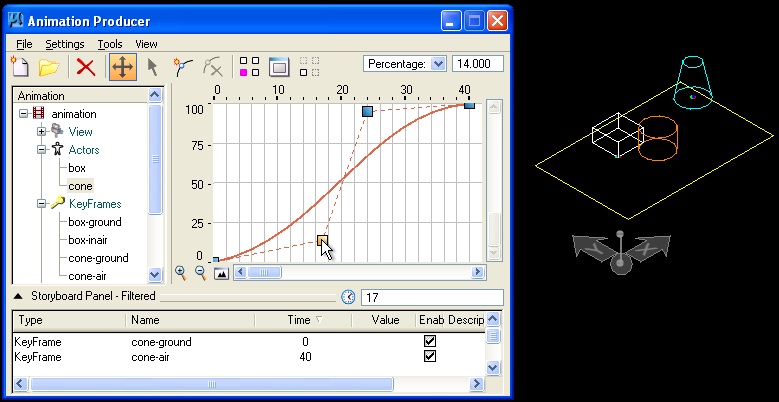
2. Throughout, remember to create new subdirectories
to keep all the rendered images of ananimation together.
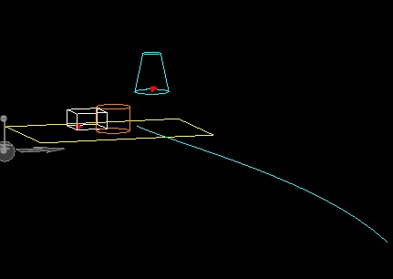
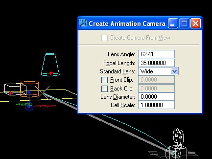
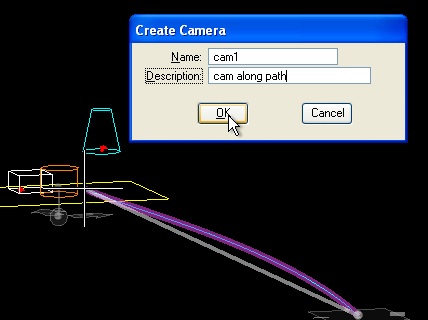
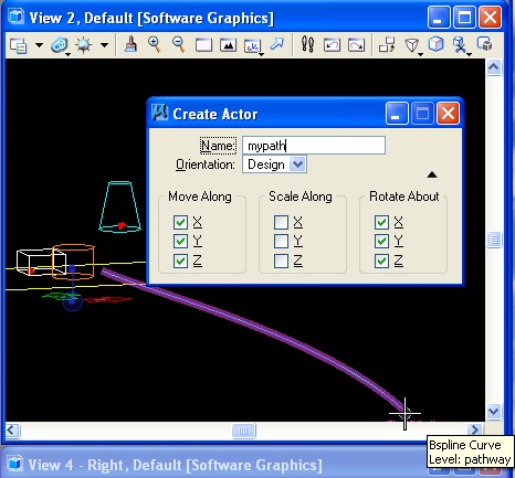
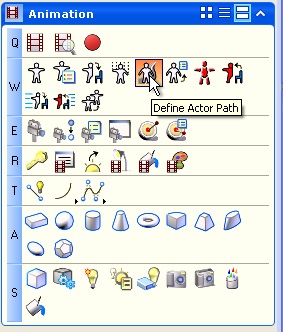
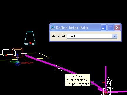
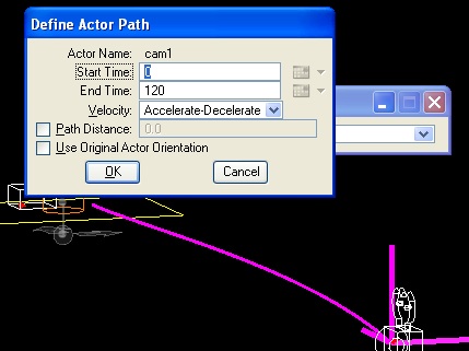
PART 4: Motion Paths
To move an actor or camera along a path. You first create a path, such as bspline. You also create a camera. You then set the actor or camera in motion along the path. The path can be a closed element (such as a block or circle), or an open element (such as a line, line string, curve, arc, or B-spline curve). You can identify the actor graphically, or you can double-click its name in the drop-down Actor List menu in the tool settings
 |
 |
 |
 |
 |
PART 5: CREATING MOVIE FILES FROM JPG FRAMES IN QUICKTIME
Animations saved as AVI can be viewed though Quicktime can be download from Apple's web site.
A series of animation frames can also be flie loaded through Quicktime Pro available
on public computers in the school and saved directly to the Quicktime mov format (e.g., myanimation.mov) for higher quality 24 bit color. Quicktime Pro is available for purchase through Apple Computer.
PART 6: Animation through Simpler One-off Options (not covered workshop)
1. Solar Animation
1. Go to: Utilities/render/solarstudy
2. Select a start time and total time
3. Pick the number frames
4. Save (AVI 16 bit) in desired drive/directory
5. Use the above steps for viewing.
2. Fly By / Through
1. Go to a plan/top view and zoom out and create a separate level on which to place your path.
2. Use a bspline curve to set your path by drawing the curve towards your model from across the screen. Go to a side view to move the curve up in space.
3. Then:
Utilities/render/flythrough
4. Fix target position
Output view 3
Raytrace
30 frames
Note: For further animation reference materials (older interface) you may want to consult the ARCH 545 website:
http://www.arch.virginia.edu/arch545/handouts.html2. GENERATIVE COMPONENTS & POLYNOMIAL EXRESSION
PART II: Generative Components (GC)
Vectors and Functions Revisited in DetailThe script file may be downloaded by selecting the links given below.
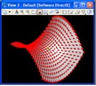
EXAMPLE 1. Hyperbolic parabolic surface by means of a basic scripting technique
We begin by establishing a point grid on the ground plane. We then use the equation of a hyerbolic parabolic surface to establish a point at a vector distance from each point on the ground plane. The full script is hyperbolicparabolicbyhand.gct.
Step 1: Create vars for resolution (e.g, 1.0) and scale (e.g., 0.2).
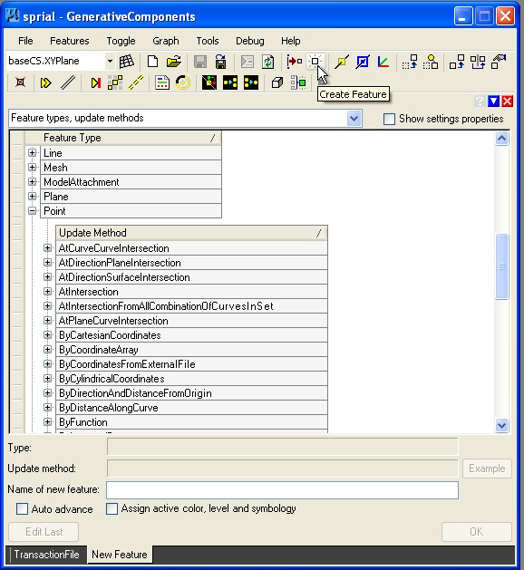
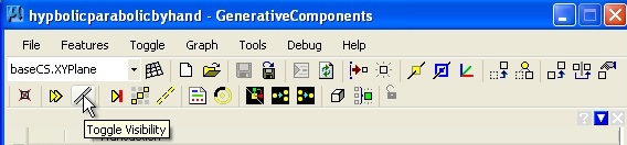
Step 2: Use Create feature tool create point01 via two Series expressions as described in the table below.
Using the ByCartesianCoordinates update method, we enter the following values.
Point01 CoordinateSystem baseCS XTranslation Series(-10,10,resolution) YTranslation Series(-10,10, resolution) ZTranslation 0
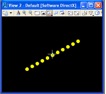
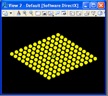
The following values points are created.
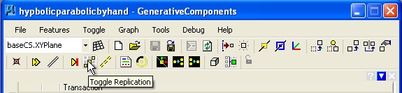
Step 3: Replicate the point
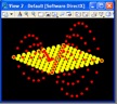
Step 4: Add a point02 at a vector direction (Zdirection) and distance (hyperbolic parabolic equation) from point01
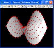
Origin point01 Direction baseCS.Zdirection DistancefromOrigin scale * ((point01.x * point01.x) – (point01.y * point01.y)) Step 5: Hide base points
Step 6: Create polygon mesh from point02