Example: Line determined by two points.
COMPUTER AIDED
ARCHITECTURAL DESIGN
Workshop10 Supplemental Notes,
Week of November 14, 2011
Generative Components and Process Based
Description
An Associative Geometrical
and Parametric Modeling Tool with Constraints
General Background
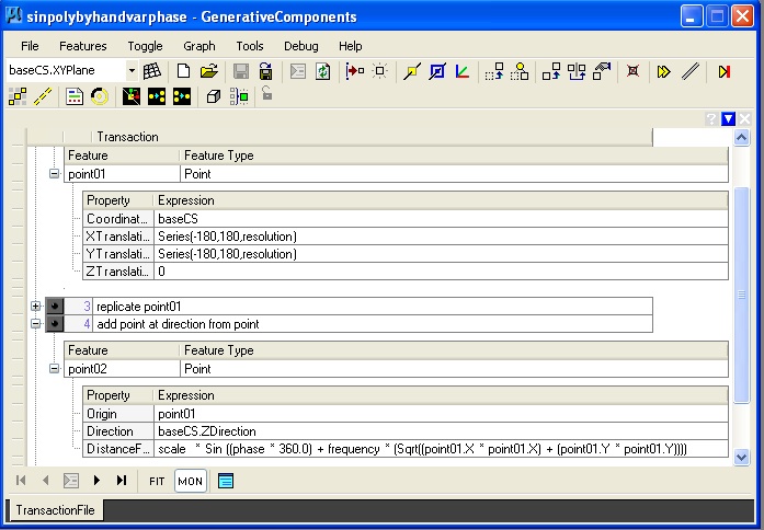
Generative Components (GC) is an associative geometrical modeling tool that uses constraints. Geometry can be associative in the sense that the transformation of one element is intentionally linked to the transformation of other elements. A constraint is a designed restriction on how elements may be transformed or in how objects may be tied together. For a simple example, a door may be associative with an opening in a wall. The resizing of a door may be automatically linked to the resizing of the opening in a wall. A door may also have constraints with respect to the hinge it rotates about. More abstract associations between geometrical elements leads to geometrical models that are more easily changed to fit emerging directions in a design project. This first hands-on introduction of GC will demonstrate the concepts needed to construct some basic geometrical elements. After Thanksgiving Break we will look at more advanced approaches, including scripting a short algorithm as a way to build geometry. Such a model can also be parametric where adjusting a few geometrical elements or parameters can dynamically regenerate the entire model.Specifics of Generative Components
The building blocks of a generative components model are referred to as features. Examples of features include a point, a line, an ellipse, an arc, a bspline, a surface, a polygon mesh. Points constitute one of the most basic feature types. Other types of features are defined in terms of points. For example, a line feature may be defined by two point features (end points).
Example:
Line determined by two points.
A symbolic graph describes the dependency relationship that exists between geometrical features. For example the “baseCS” coordinate system is the basis for the definition of two points, and, in turn, the points are the basis for the definition of a line. Within most CAD systems, these dependency relationships are somewhat hidden from the end user. Within Generative Components these dependency relationships are more explicitly developed by and represented as a graph to the end user. Given the dependency relationships, the user can more self-evidently move any one of the points so as to more directly redefine the line.
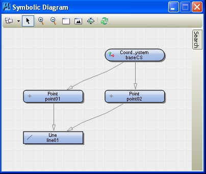
Directed
symbolic graph of elements.
Similarly, points can determine a bspline curve. In turn, bspline curves can determine surfaces. And, surfaces can determine the components of a paneling system. In such a more elaborate set of dependencies, these directed relationships are defined such that if the designer changes the locations of any of the points then the system automatically propagates changes to geometry determined by the points in a kind of chain reaction. For example,if the points are changed and they are used to determine bsplines, then the bsplines will automatically be changed, and in turn, if the bsplines determine surfaces, then the surfaces will automatically be changed and, again in turn, the surfaces may propagate changes to a paneling system. By making accessible all the elements of this dependency hierarchy, it is easier to make dynamic changes to a computer model.
Variables
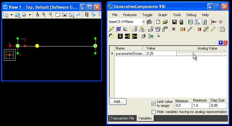
Variables can be used to store values in memory that are the basis for describing geometrical elements and their numerically ordered relationships. In the example below, parametricPtOnLine.gct, a graph variable named "parameticDistance1" is created to determine a local point at a parametric distance along a line:
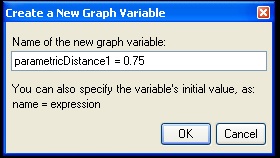
A graph variable may also be setup to have a limited range in values, such as between 0 and 1 and only in increments of 0.05 (i.e., 0.0, 0.05, 0.1, 0.15 …. 1.0).
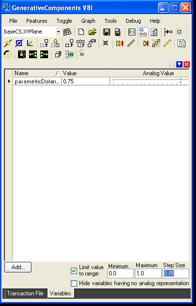
Graph
variable “parametricDistance” with incemental
values of 0.05
Once a graph variable has been created, you can use it to dynamically
control the location of a point feature along the line. Here the point
"feature" is created using a "ByParameterAlongCurve" so-called update method.
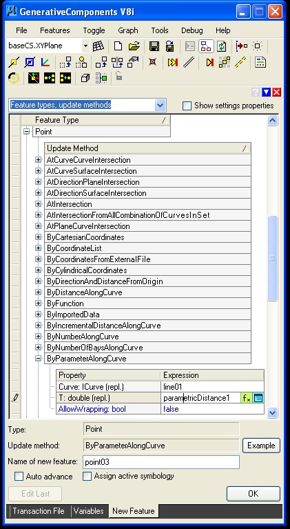
Point determined ByParameterAlongCurve update method.
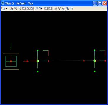
The new point appears as depicted in the image below.
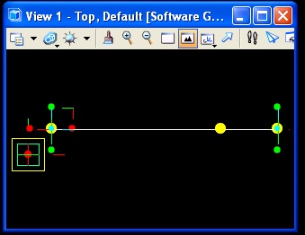
Interactively changing the the value of the parameter dynamically changes the location of the point along the line.
Series and Geometry
A Series (1,5,1) refers to a sequence of numbers that begins with the number 1, concludes with the number 5, and that is incremented by the step size of 1. That is, the Series (1,5,1) is the set of numbers 1, 2, 3, 4, 5. More generally, the series notation system is specified in terms of (start value, max value, step size value). Series are used to determine a set of cylindrical points in the next example below.
Update Methods
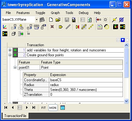
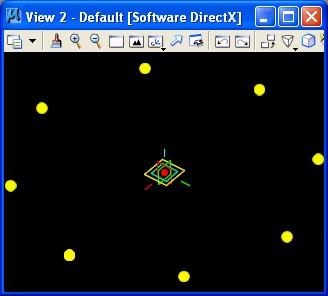
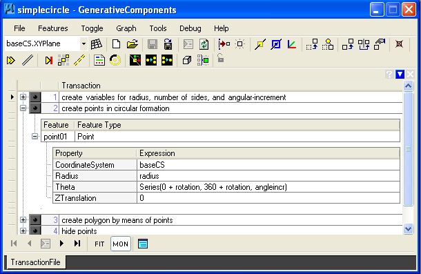
For geometrical features such as points, lines, arcs, etc., there are a variety of update methods that may be used to initiate as well as update the description of them. In the dialog box below, a point feature is defined in terms a series expression incorporated into the “ByCylindricalCoordinates” update method. For example, in the example of simplecircle.gct, the variable “numcorners” is an integer used to determine the number of points in the circular array depicted below. The variable “radius” is a decimal number used to determine the distance of the points from the center of the base coordinate system (baseCS).
 |
 |
Within the dialog box above, a cylindrical point array is defined with the use of the variables “radius” and “numcorners”. Alternatively , the cylindrical “point01” could have been described in terms of 1) the coordinate system "baseCS", 2) its fixed radius distance of "1"master units (feet) from the origin of the coordinate system, 3) an angular rotation of "45" from the x-axis of the coordinate system, and 4) a height of "0" master units along the z-axis of the coordinate system. That is, the point point01 could have been defined with the following values plugged into the update method:
|
CoordinateSystem |
baseCS |
|
Radius |
1 |
|
Theta |
45 |
|
Ztranslation |
0 |
|
CoordinateSystem |
baseCS |
|
Radius |
1 |
|
Theta |
Series (0, 360, 360/ numcorners) |
|
Ztranslation |
0 |
If the numcorners = 8, The expression "Theta = Series (0, 360, 360/ numcorners)" establishes the series of points at rotation values of 0, 45, 90, 135, 180, 225, 270, 315, and 360 degrees, thus generating eight points in the array depicted in the figure above at the height of z = 0.
Examples
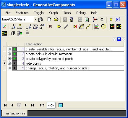
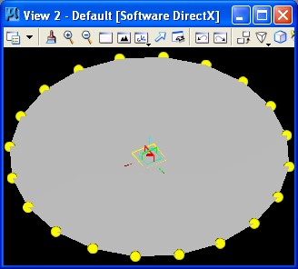
1. Simple Circle: simplecircle.gct
 |
 |
Key update method description of
point series:
Some of the remaining examples below also use series statements to generate a repeating pattern. These examples also demonstrate a range of update methods. These will be referred to in greater detail in class.
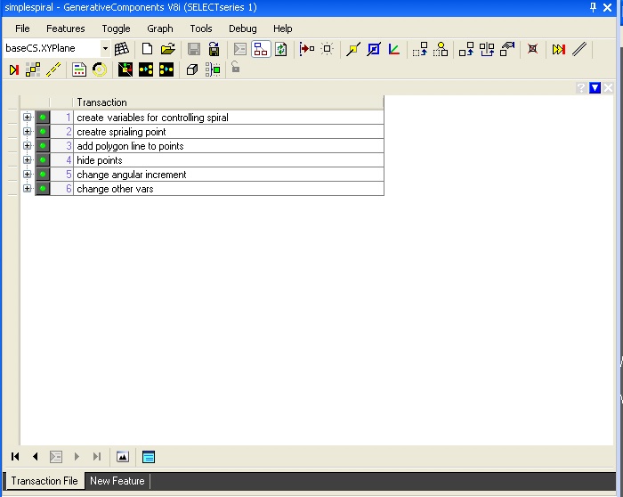
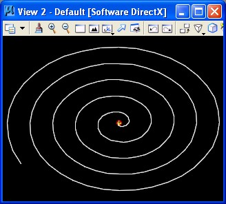
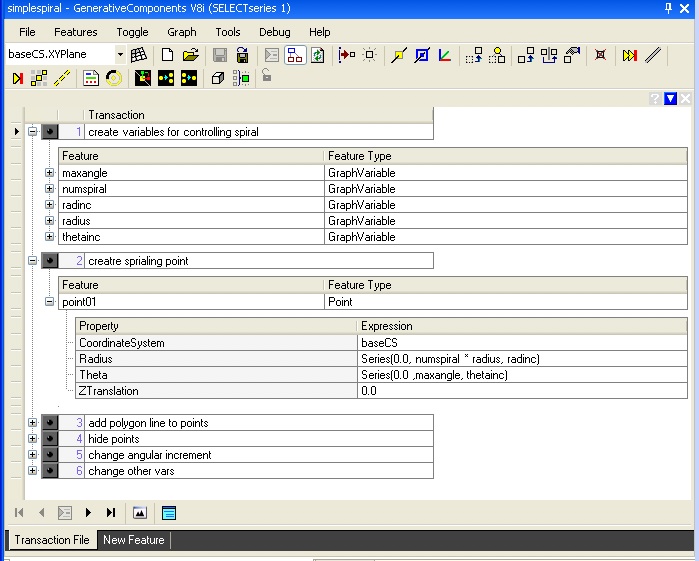
2. Simple
Spiral: simplespiral.gct
 |
 |
Key update method description of point series:
3. Helix: helix.gct
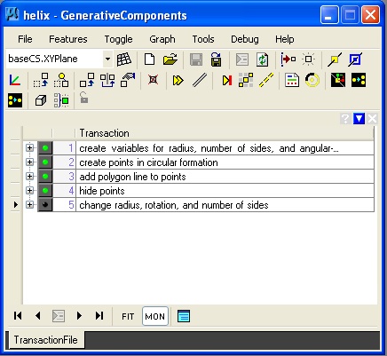 |
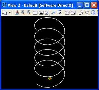 |
Key update method description of point series:

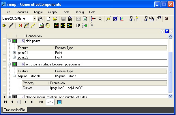
4. Ramp: ramp.gct
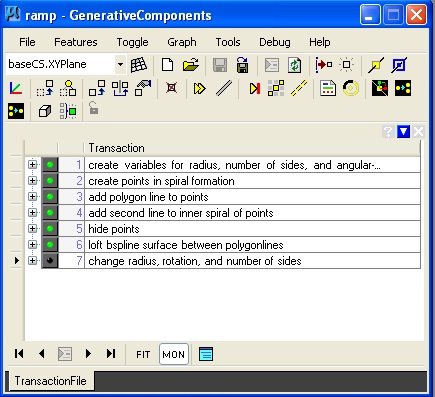 |
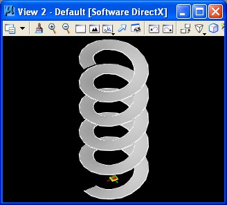 |
Key update method description of bspline surface:
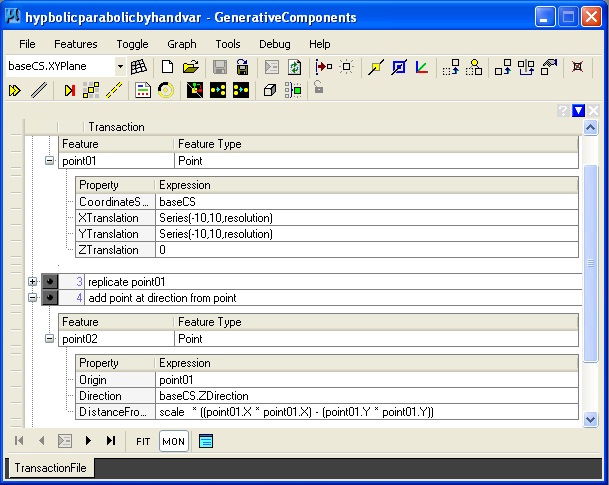
5. Hyperbolic Parabolic Surface: hyperbolicparabolic.gct
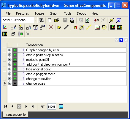 |
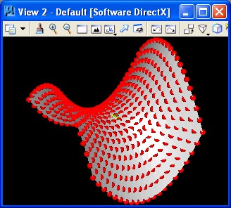 |
Key update method description of point series:
6. Sin Surface: sinsurface.gct
 |
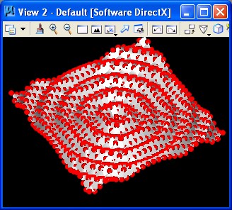 |
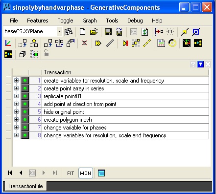
Key update methods description of point series: