COMPUTER AIDED
ARCHITECTURAL DESIGN
Workshop 11 Notes,
Week of November 28, 2011
Bentley Architecture,
Editing Solids by Projection, Generative Components Ramp and Surface Editing
1. Bentley Architecture
STEP 1: STAIRS
Open Bentley Architecture V8i and create a new file (e.g., "building.dgn").
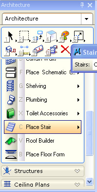
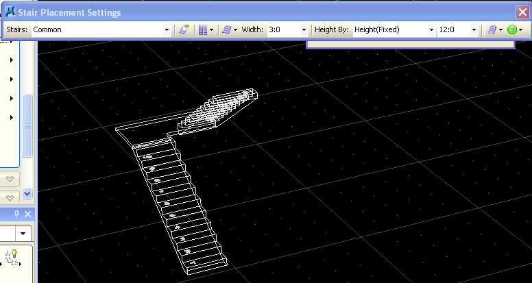
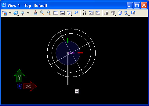
In the floors task, create a stair of Half-turn by locating a point on the ground, designating the size platform, and then giving the stair orientation.
|
|
STEP 2: WALLS
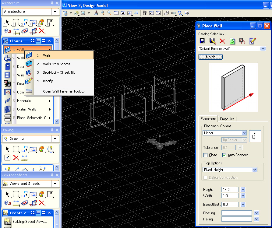
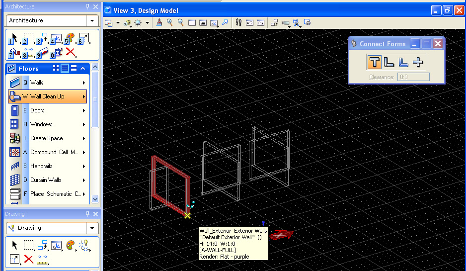
In the Generic Forms task, create four sets over overlapping "Linear Forms" walls forming a "X" intersection, either directly or by copying a pair of walls.
In the floors task, use the Connect Forms/Connect Forms tool to perform T, and Cross, and to L Shape Joint. Note that dominant wall is selected last.
STEP 3: ROOF
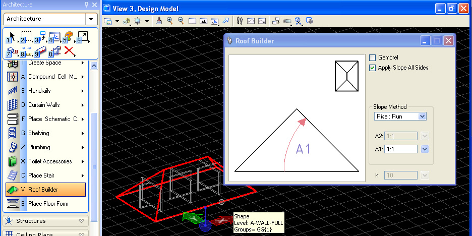
Build a simple shed roof from a rectangle in the gound plane.
In the floors
task,
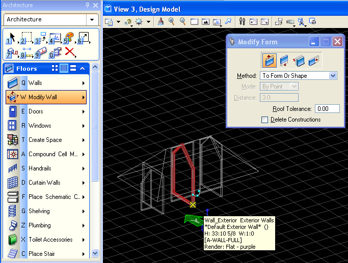
use the Floors/Modify Wall/Modify Form tool and "To Form or Shape" tool
to connect the walls to the roof
forms .
Note :
1. first select all the roof elements with the left-mouse
button.
2. confirm these elements with the left-mouse button.
3. reset the mouse with the right-mouse button.
4. select all the walls one at a time and they will project to the roof
element.
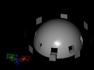
2. Edit Dome by Projection
Step 1: From the Solids Modeling task, create a solid sphere using the "E3" tool.
Step 2: Shell the solid sphere with the "T5" tool.
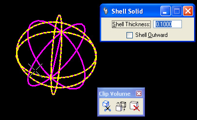
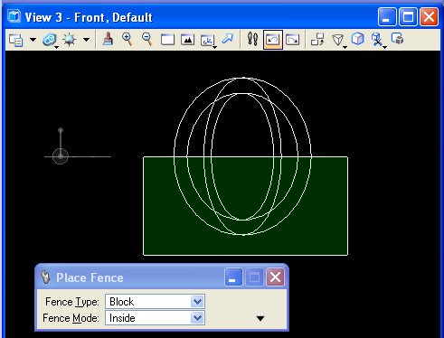
Step 3: Use the Place Fence tool (#2 top task) to superimpose a fence over the lower-half of the solid sphere in the front view.
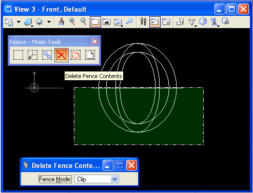
Step 4: Open the fence tools sub-palette by clicking on the #2 tool, and from the front view, use the "Delete Fence Contents" tool, switch the Fence Mode to "Clip" and cllick inside the front view to subtract the lower portion of the sphere.
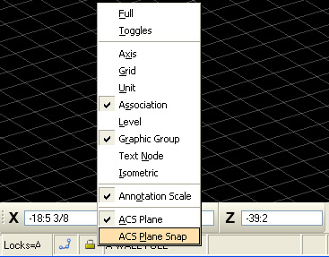
Step 4: From the front elevation, set ACS in the front view, and create a rectangular shape with the Solids Modeling "W1" tool that sits on the elevation sphere.
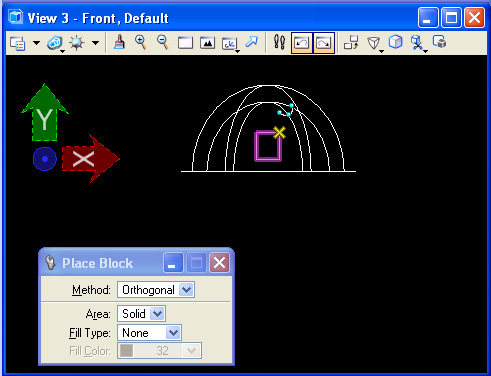
Step 5: Move the rectangle outside the sphere.
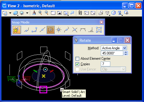
Step 6: Using the center snap on the sphere, rotate and copy the square around the center of the sphere 7 times at 45 degrees each.
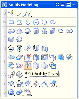
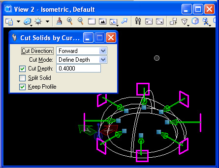
Step 7: Preselect all of the rectangles. Use the cut surface tool "T11" to cut the rectangular shape through the dome, with "Cut Direction" set to "Forward", "Cut Mode" set to "Define Depth", "Cut Depth" set to on with a depth (e.g., 0.4000) that projects the rectangular shape past the outside wall of the dome and "Keep Profile" to on. Select the dome solid to complete the operation.
|
 |
 |
3. GC Ramp Example
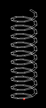
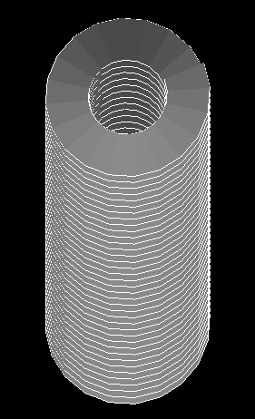
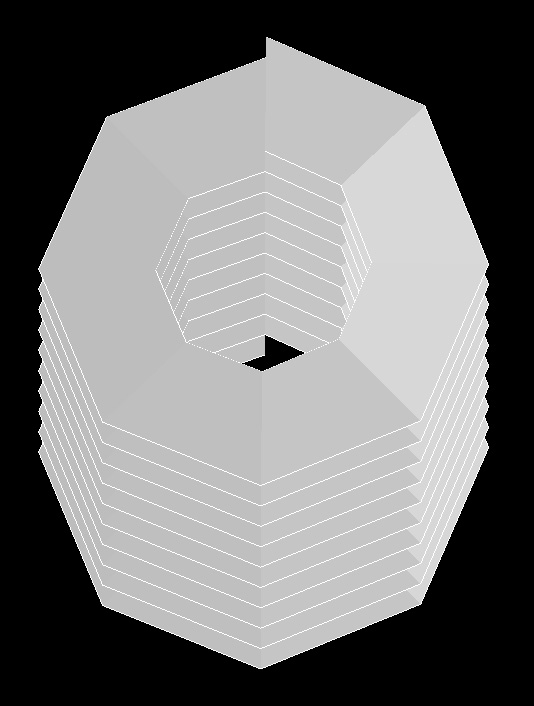
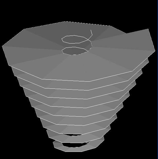
The script ramp.gct is based upon a set of steps and expressions to generate two parallel sets of spiraling points. Each set of spiraling points is connected by an open polygon line. The two parallel polygon lines in turn contitute two edges a polygon surface. A set of parametrical variables can be used to modify the characteristics of the spiraling ramp. We will reconstruct ramp.gct here, but you can load it directly from the link ramp.gct for reference.
 |
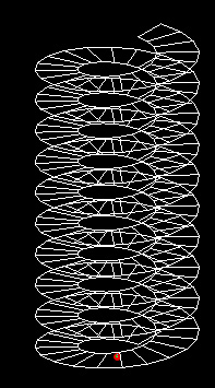 |
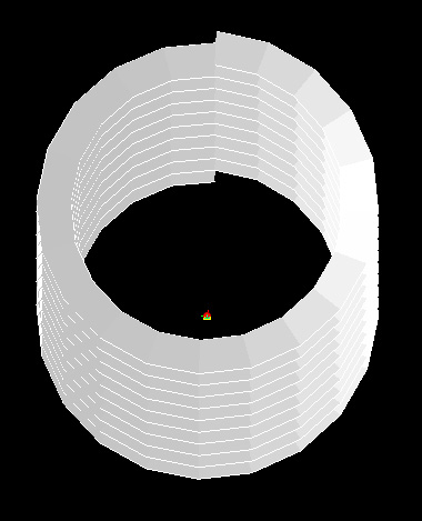
| Ramp Before Modification | Ramp After Modification |
Open
Generative Components, and created variables to determine
“floorheight”,
“numfloors”, “numsides”,
“angleincrement”,
“radius1” and “radius2”. In Generative
Components, the use of the Graph/Manage Graph Variables dialog box
includes setting numerical values for the minimum, maximum and step
sizes for all of these variables except for the variable
“angleincrement”.
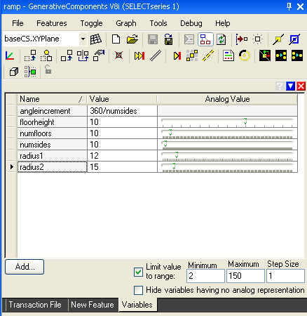
The variable “angleincrement” is a “dependent” variable that is defined on the basis of the “numsides” variable (i.e., angleincrement = 360 / numsides). The other variables are “independent” in that they are not defined on the basis of other variables. Each variable is to be initialized according to the following table:
|
Expression |
Min |
Max |
Step Size |
Purpose |
|
floorheight = 10 |
1 |
20 |
1 |
the height of any 360 loop within a spiral |
|
numsides = 10 |
3 |
360 |
1 |
the number of sides in each loop of a spiral |
|
numfloors = 10 |
1 |
20 |
1 |
the number of 360 loops within a spiral |
|
angleincrement = 360 / numsides |
|
|
|
angular increment between points in a spiral |
|
radius1 = 12 |
1 |
100 |
1 |
the inner radius of the ramp |
|
radius2 = 15 |
2 |
120 |
1 |
the outer radius of the ramp |
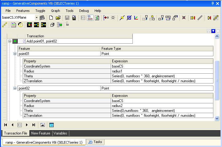
Step 2: Initiate the inner and outer points within the two parallel spirals. Each point is defined using the “ByCylindricalCoordinates” update method. Within this method, a “Series” statement is used for “Theta”, the angular increment between each point. Another “Series” statement is used for “ZTranslation”, the rise in height of each point. In general the “Series” statement includes three numbers: an initial value, a final value and an interim step value. Thus the statement “Series{0, 6, 2}” is the series of numbers 0, 2, 4 and 6. Below, the set of points “point01” is the first series of inner spiraling points, and the set of points “point02” is the second series of outer spiraling points.
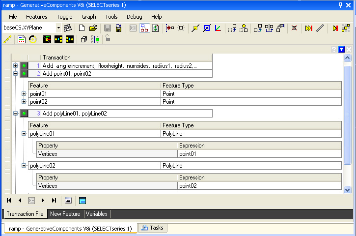
Step 3: A polyLine feature is threaded through each
of the two spiraling sets of points, “point01” and
“point02” by using the “ByVertices” update
method. Note that these polyLines are actually not used to generate the ramp in the steps that follow. Rather they provide a simple visual check on the presence of the spirals.
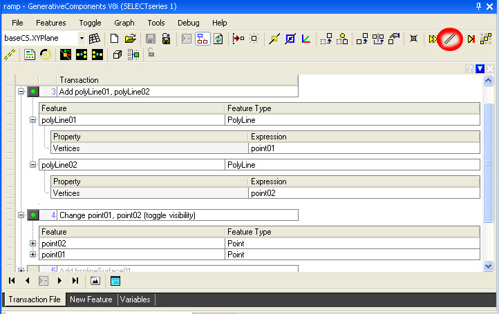
Step 4: Turn off the visibility of the spiraling
points using the “toggle visibility” tool (3rd icon from
right-hand side, the diagonal line highlighted with a red circle in the
top row of icons in the figure below).
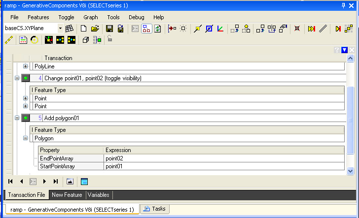
Step 5: Create a polygon surface “polygon01” between the two polyLines by using the "ByLacing" method and entering point01 and point02 into the text boxes labelled "StartPointArray" and EndPointArray".
Note that the variables can be modified so that each loop in the spiral’s number of sides may be changed, the radii of the inner and outer edge of the spiral can be changed, the height of each 360 turn of the spiral can be changed, and the overall number of loops within the spiral can be changed.
Part 1: How could you modify a value of variable in
the GC script above such that it draws twenty loops within the spiral?
Part 2: How could you modify a value of variable in the GC script above such that it draws a spiraling octagon within each loop of the spiral?
Part 3: In step 1, how could you have initialized
the variable radius2 as a dependent variable upon radius1 such that the
ramp surface is always 10 units wide?
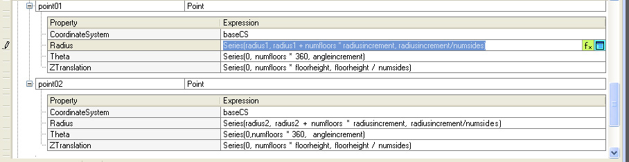
Part 4: Assume that you had initialized a new
variable named “radiusincrement” in step one that can have
a minimum value of 1, a maximum value of 5, and a step size of
0.5. Also assume that in step 2, we had initialized the values of
Radius for point1 and point2 as a Series, where for point1 the value of
Radius is set to:
Series(radius1, radius1 + numfloors * radiusincrement,
radiusincrement/numsides);
and for point2 the value of Radius is set to:
Series(radius2, radius2 + numfloors * radiusincrement,
radiusincrement/numsides);
These revised values for point01 and point02 are shown in the figure below.
These modifications impact the ramp as it rises from the ground so as to form an increasingly wider outward spiral.
Also, requiring the use of Series statements is the GC script file bananatruss.gct. The script contains an embedded polygon function. This is loosely modelled after Grimshaw's WaterLoo Terminal study developed by Robert Aish, initial author of GC, though is simplified for didactic purposes.
4. Distributed Rendering
Follow the steps outined in the documentation on-line: