COMPUTER AIDED ARCHITECTURAL DESIGN
Workshop 7 Notes, Week of October 24, 2011
INTRO TO LIGHTING AND RENDERING IN RHINO
PART 1. LIGHTING
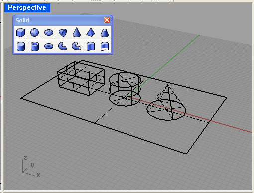
1. Create a Rhino Model with a ground plane surface and three solids as follows:
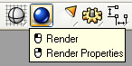
2. Open the lighitng icon from upper right-hand side of screen.
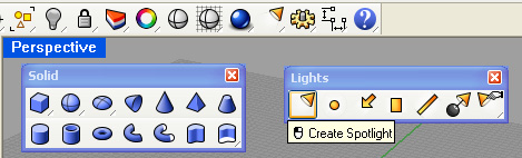
3. Place a spot light in the model from the front view, entering the target and radius first, and then the light location second.
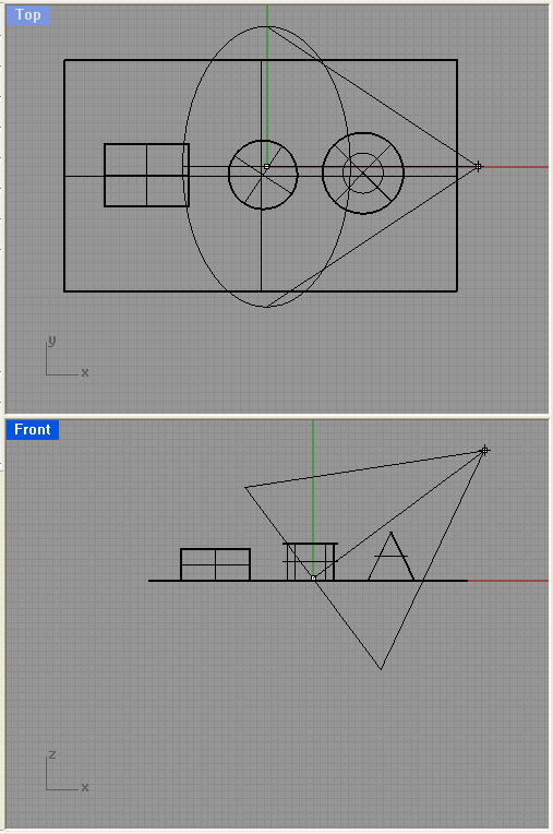
4. Turn on the planar lock. Select the light and turn the control points to on.
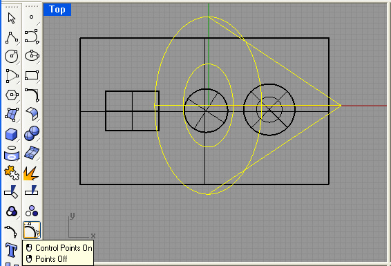
5. From the top view, move the lighting source position to the +x, -y position relative to the ground plane.
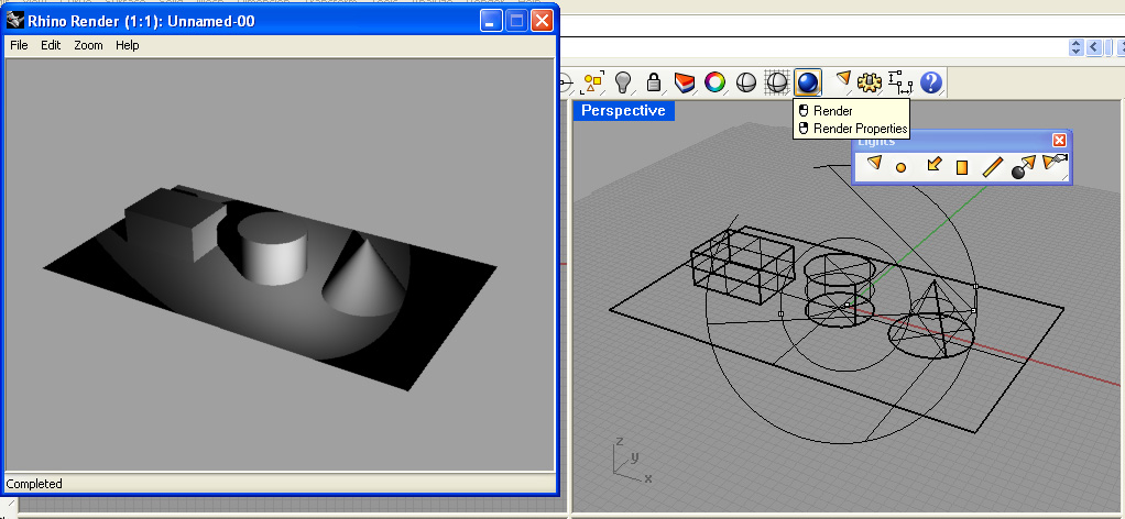
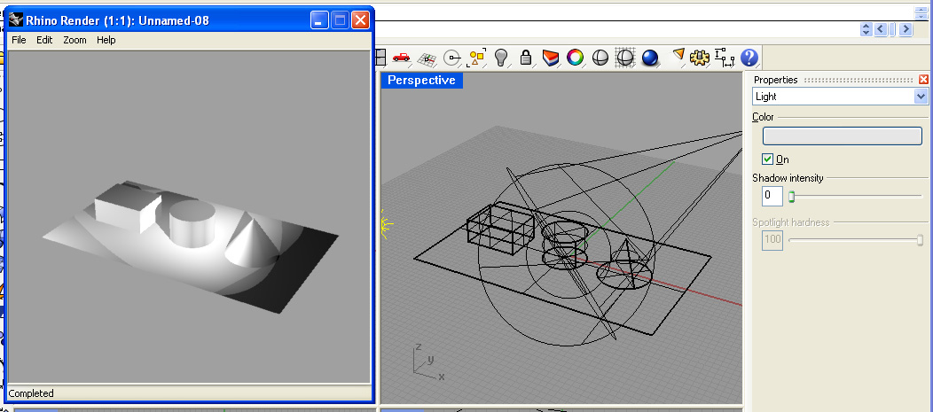
5. Activate the perspective window, select the rendering icon, and render the view.
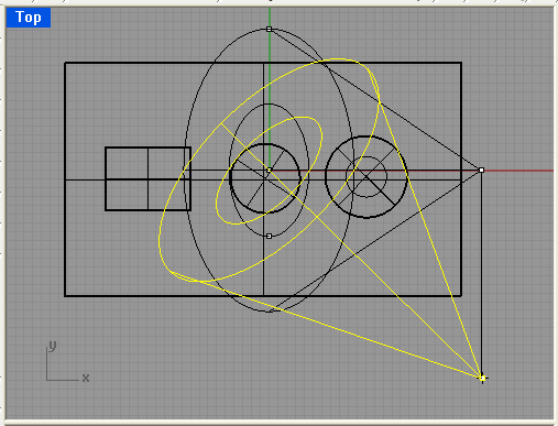
6. Following a similar procedure, create a back spot light pointing towards the center of the model and create a rendering.
 7.
7.
7. Select the properties icon for the back light and reduce the shadow intensity to 0.
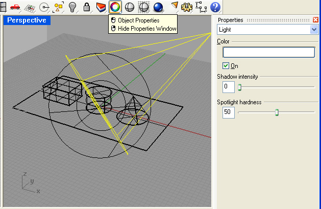
8. Render the perspective window again and note that the second light is no longer casting a shadow.
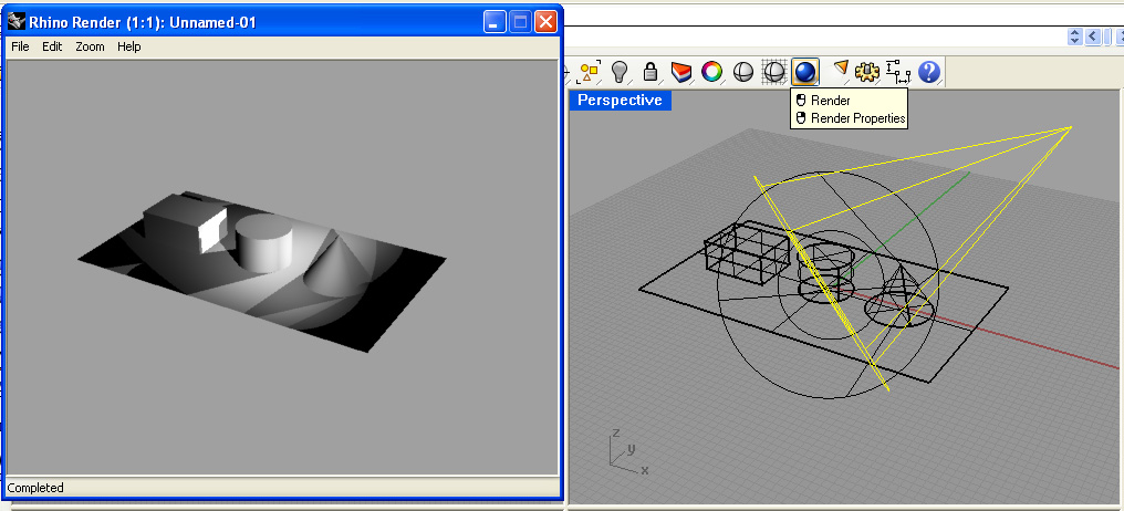
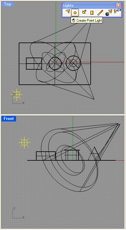
9. Add a point light to the upper left hand corner of the model. Here it is only necessary to position the light source. Begin in the front view and continue to place the light in the top view similar to setting the light source lcoation for the spot light.
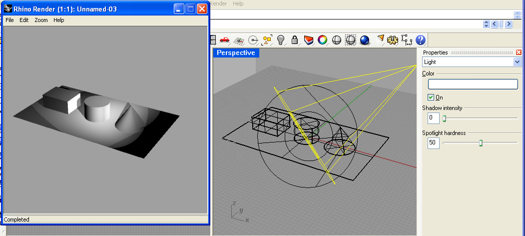
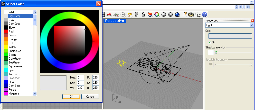
10. Using the properties icon, adjust the shadow intensity of the point light to 0 and the color to gray.
11. Render the perspective again for a rough simulation of three points lighting.
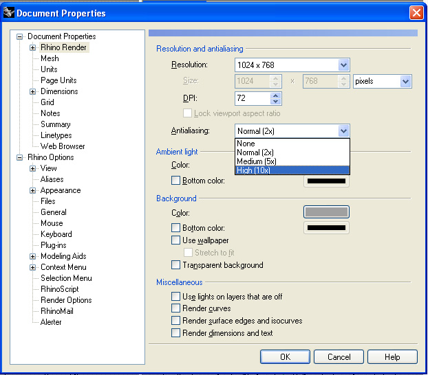
12. Note that the edges of the geometry running diagonally across the rendering are jagged, such as on the cone and the box.. This is due to aliasing. To correct for this, open up the render properties dialog.
PART 2. RENDERING
1. Within the render properties dial box, set the antialiasing to high and the screen resolution to 1024 x 768 pixels.
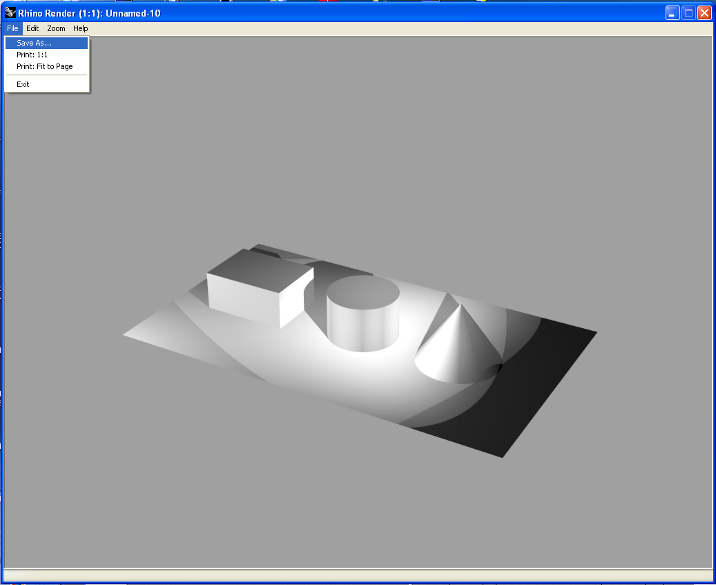
2. Render the perspective view and note the anti-aliasing effect as well as the image size. From within the Rhino Render window, use the File/Save As Option to save the rendeirng to a jpg or tif image.
3. You can continue to adjust the antialiasing level by rendering the same modeling within a more advanced rendeing tool as we will see in a later tutorial.
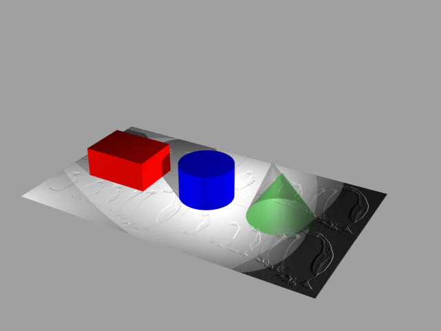
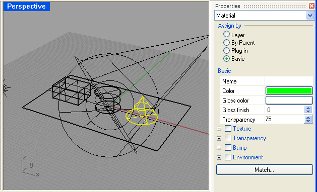
4. Using the same properties icon as before, set the material colors of the box, cylinder and cone to red, blue and green, and also make the cone transparent. Note that the "Material" pull-down tab is active, that the "basic" assign by method is selected, and that for the cone, the transparency value is set to 0.75. Do not sleect the "Transparency Check Box" which refers to a separate material property.
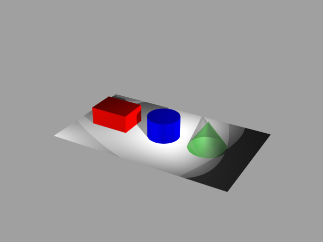
5. Rendering the view to 640 by 480 pixel resolution results in the following jpg file.
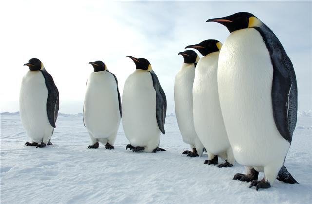
6. Download the image of penguins below by right clicking on it and saving it to your local working folder.
7. Now select the ground rectangle, open up the properties dialog, select the check-box for "Bump" and also select the "+" symbol for "Bump". Load the file above through the map file interface. Adjust the "tiling" to 1 by 1, and render.
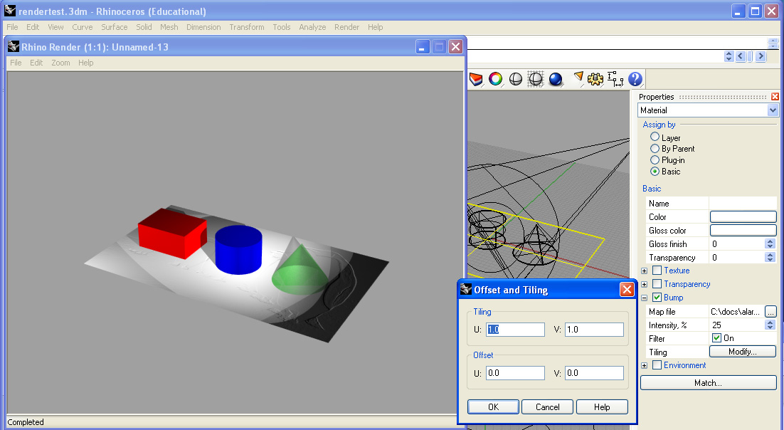
8. Within the same dialog box, adjust the tiling to 2 x 2 , increase the intensity to 75 %, adjust the gloss finish to 50, and re-render.