
COMPUTER AIDED ARCHITECTURAL DESIGN
Workshop 4 Notes, Week of September 23, 2012
INTRO TO SURFACES, FEATURE SOLIDS, ACS AND ACCUDRAW REVISITED
1. SURFACES
Load the file Classes\Arch3410-6410-Mark-F11\Examples\surfaces\surfs.dgn. In the Surface Modeling Task list, retrieve the tool boxes associated with icons labelled "E" and "R" below, and use the tool specified in each case of a surface type entity as indicated below.


 |
 |
| select edges | generated edge defined surface |

 |
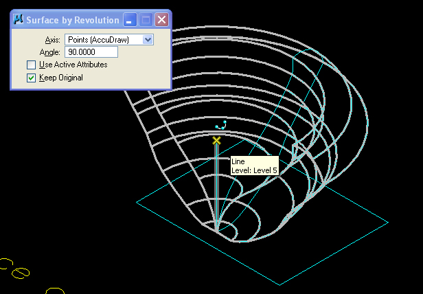 |
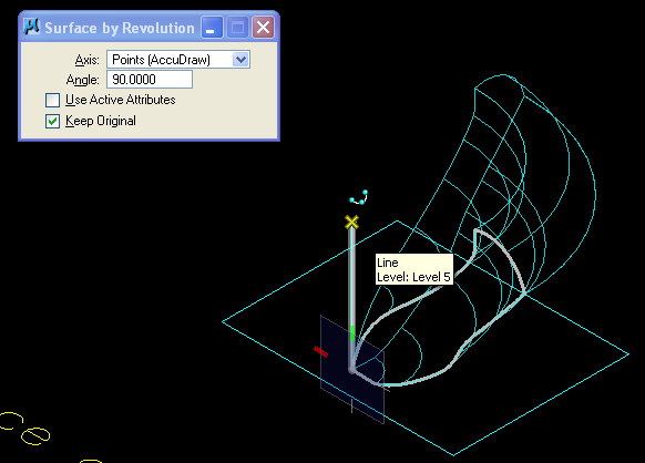
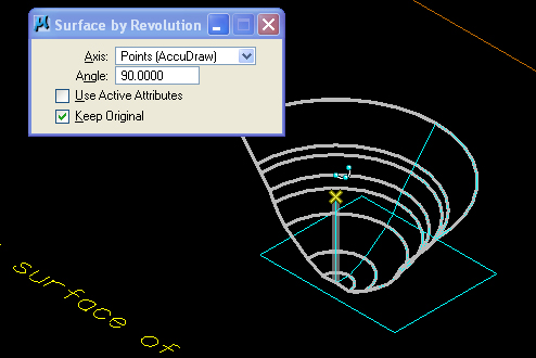
| Selecting the profile curve and the upper and lower portion of the vertical axis sweeps out 90 degree surface | Enter a data point off the geometrical elements to sweep out next 90 degrees of surface. |
 |
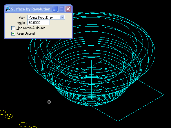 |
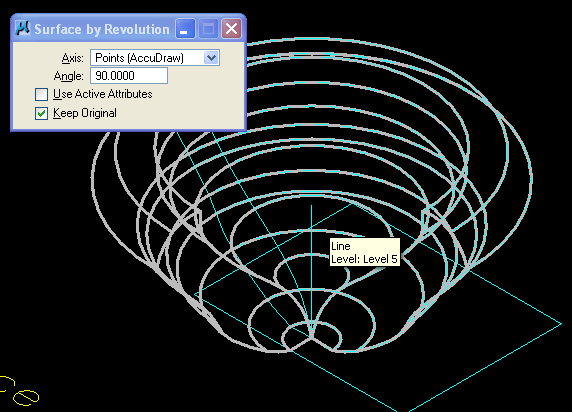
| Enter a data point again to sweep out the third 90 degree surface (= 270 degrees). | A fourth data point will sweep out the full 360 degrees. |

 |
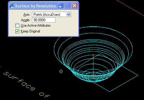 |
| Selecting the profile curve and the upper and lower portion of the vertical axis sweeps out 90 degree surface | Enter a data point off the geometrical elements to sweep out next 90 degrees of surface |

 |
 |
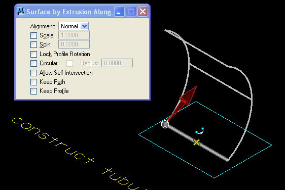
| dialog box settings | preexisting condition |
 |
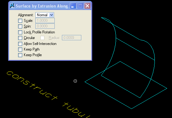 |
| select profile curve and then horizontal line along ground to generate tenative surface | accept with left mouse button data point to yield this final result |

 |
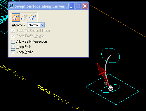 |
| the Sweep Two Along One option is selected | select the profile curve |
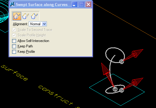 |
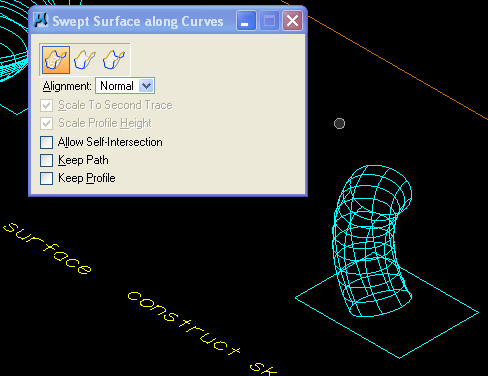 |
| select the end curves | enter an additional data point to accept the generated surface |
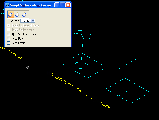 |
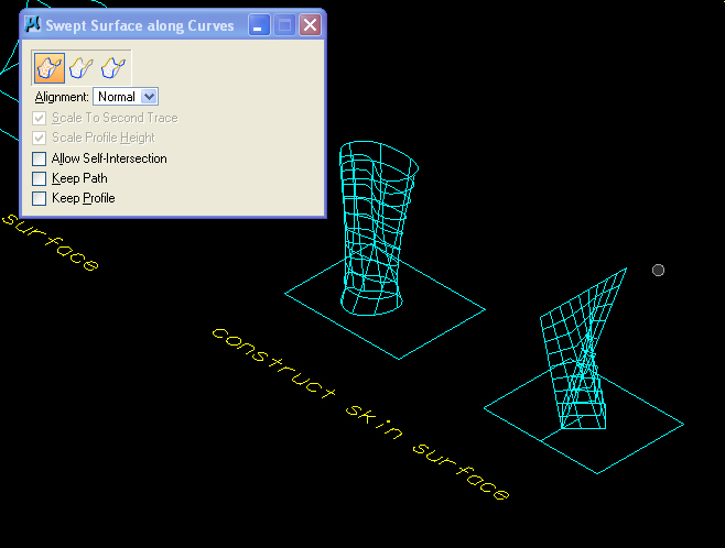 |
| The Sweep Two along One option also selected for each of the two cases above | select the profile curve, and then select the end curves in each case, enter an additional data point to accept the surfaces |
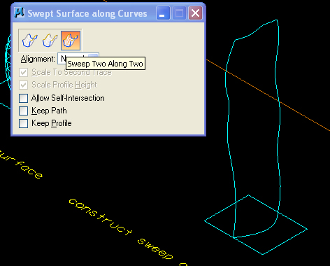 |
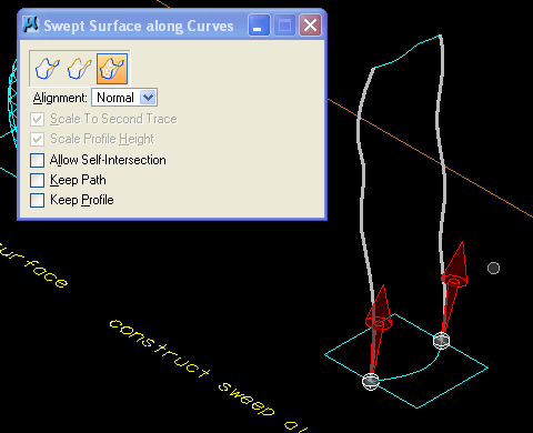 |
| select the profile curves | |
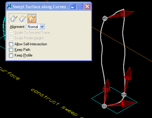 |
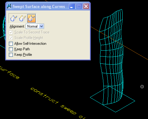 |
| select the end curves | enter an additional data point to accept the generated surface |
 |
 |
| surfaces rendered in wireframe | surfaces rendered in phong shading |
2. FEATURE SOLIDS OR SMART SOLIDS
Create block with the Slab Feature tool from the Feature Solids Menu

 |
|
Enter Holes

 |
 |
Move Holes

 |
 |
 |
 |
Modify Dimension of Holes

 |
 |
Modify Edges With Blend Feature

 |
 |
 |
 |
3. SIMPLE SADDLE REVISITED (FROM LECTURE)
1. With ACS Plane Lock set to On, Create a 12 x12 rectangle (place block tool) in the ground plane.

2. Using the "F" front Accudraw rotation plane, create vertical lines in opposite corners at 7 and 11 feet high each.
 |
 |
3. In the Sufaces Menu, generate a surface from four corner points.

 |
 |
4. In the Feature Solids menu, thicken the surface 1.0 feet.

 |
 |
5. Add a hole to the center of the new solid, using the same methods applied to the slab above.
 |
 |
6. Copy the hole using the Move Feature tool, using the same methods applied to the slab above.
 |
 |
7. Change the dimesions
of the hole using the "Modify Solid or Feature" tool, using the same
methods applied to the slab in the earlier example.
 |
 |
8. The same "Modify Solid or Feature" tool can be use to thicken the simple saddle roof.
 |
 |

4. . ACS and ACCUDRAW
ACS and ACCUDRAW are two inter-related but two distinct ways of establishing construction planes. The ACS, Auxilliary Coordinate System, is set into place on a more continuous basis and can be moved into any location and orientation. ACCUDRAW, a consturction plane compass, is set into place on a more transitory basis, and can be very quickly rotated and setup in relationship to the the active ACS. The combination of both systems affords quick and contextually sensitive options to build construction planes as needed.
ACS = Auxilliary
Coordinate System. The ACS is the active construction plane, a two
dimensional plane on which you create data points.
ACCUDRAW = The Accudraw Compass. The ACCUDRAW compass is a construction
plane that is defined in relationship to the ACS. It is accssible
through a set of QUICK KEYS (e.g, "F" - front, etc.). By default, it is
co-planar with the ACS.
5. ACCUDRAW AND AUXILLIARY COORDINATE SYSTEM (ACS) REVISITED
1. 2d plane rotate 90 degrees on any axis (draw circles, arcs, etc.) (QUICK KEYS: "RX", or "RY", or "RZ")
Enter the first data point on the current Accudraw construction plan, enter the letter "O" for offset, and then use one of the following quick key combinations to rotate Accudraw around the x, y, or z axis:
Accudraw via "RX" key
transforms to rotation of 90 degrees around x-axis.
Accudraw via "RY" key transforms to rotation of 90 degrees around
y-axis.
Accudraw via "RZ" key transforms to rotation of 90 degrees around
z-axis.
2. Menu item utilities/auxiliary coordinates for ACS options:

2.1a The current ACS can be saved under a named identity with the "Create new ACS icon"

2.1b Alternatively, save “base” (default ACS) via Accudraw
by selecting Accudraw dialog box and using the quick key combination
"WA"


2.2 Redefine ACS (three point method). Note that the red and green
arrows are rotated into the new position.

2.3 Similar to example 2.1, we can use the save the current ACS as
“shed":

2.4 Double-clicking on “base” restores the ACS "base":

2.5 Alternatively, using Accudraw, the quick key combination "GA"
restores ("gets ACS") the ACS "shed":

3. ACS via TOOLS Menu
Menu item tools/auxiliary coordinates obtains a separate dialog box
thatalso allows the following ACS operations:
icon 1: define acs with element (select front rectangle of cube, fix
acs to it.

icon 2: define acs with 3 points (on face of cube)

icon 3: align acs with view
icon 4: align with attached reference file (skip)
icon 5: rotate it by value
icon 6: move it (if time)
icon 7: select ACS (similar quick key "GA”)