COMPUTER
AIDED
ARCHITECTURAL DESIGN
Workshop 12
Notes,
Week of November 26, 2012
TEXTURE MAPPING, REAL SCALE AND ADDITIONAL MATERIAL PROPERTIES (DRAFT NOTES)
Part I: Maxwell in Rhino Continued
The Rhino plugin for Maxwell addresses scale according to two different settings. Map projection is in part handled via Rhino's separate texture mapping control. Combining Maxwell and Rhino tools, texture mapping can be developed with great flexibilty to match specific object conditions.
For a more complete treatment of these techniques in Maxwell see See Maxwell For Rhino Plugin Manual
Within workshop Notes 6, the technique of making a basic texture map was illustrated in Rhino. Within workshop Notes 10, those techniques were expanded for Luxology. Similarly, here, the techniques for texture mapping are expanded for Maxell.
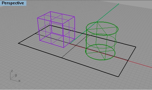
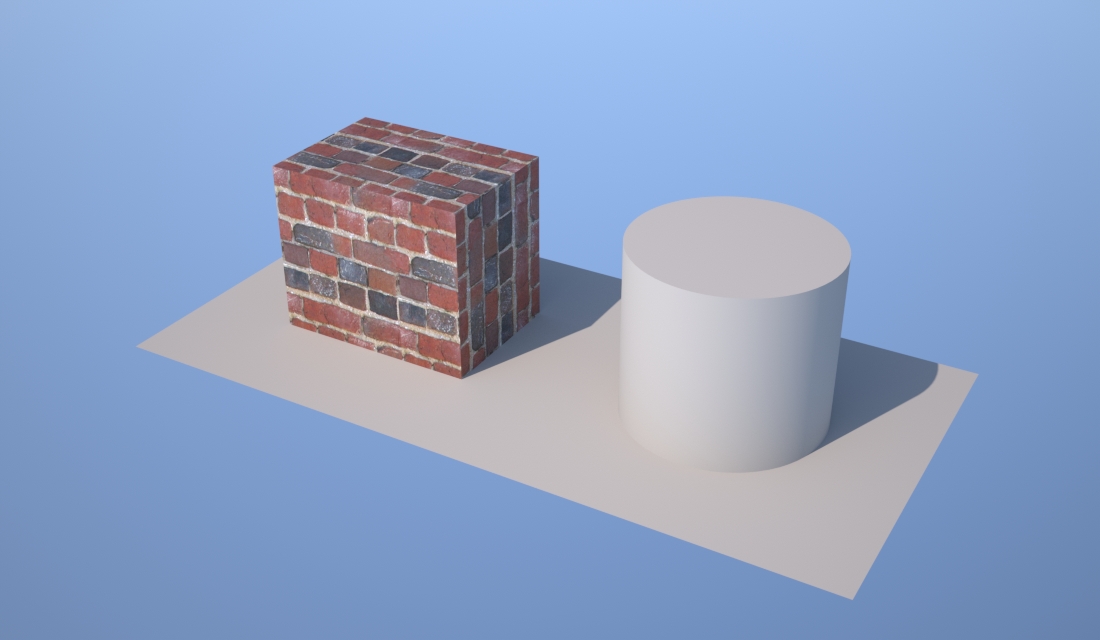
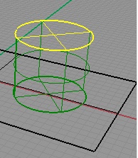
Begin by making a solid box and a cylinder, and place these objects on a simple planar surface.
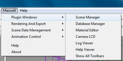
Go to the Maxwell Menu and Open the Maxwell Scene Manager:
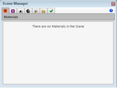
Next, go the Materials tab
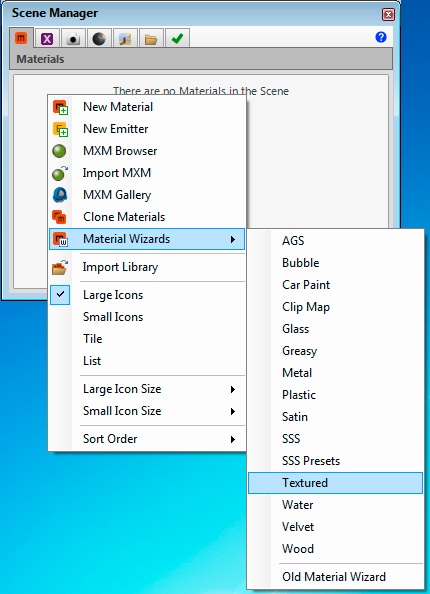
Right-click in the white area of the dialog box, select the "Material Wizards" option to create a new material, and select the "Textured Option".
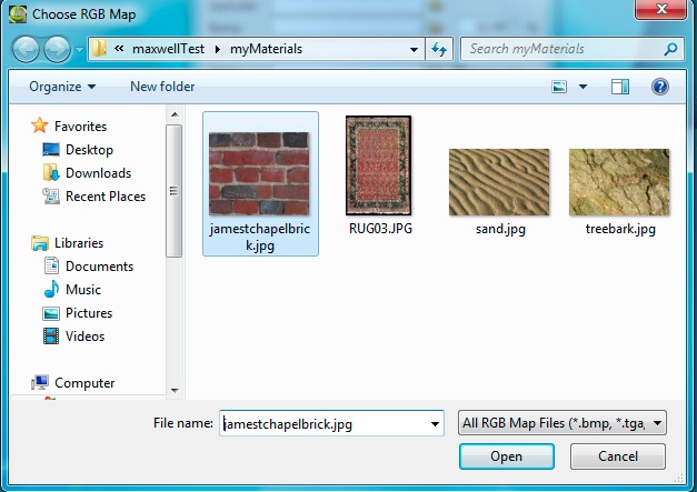
Within the "Textured Wizard" dialog box, choose the yellow folder icon adjacent to "Color" and select an image file:
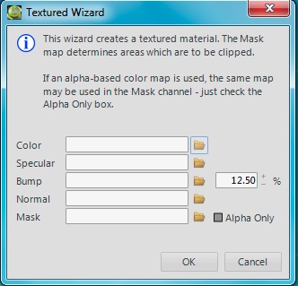
Load in a texture map based upon a jpg image file.
Similarly, choose the brick photo for the bump map such that both the "Color" and "Bump" map areas now include links to the jpg texture.
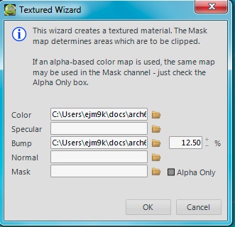
Next, select the OK button, and the material appears in the Scene Manager Library.
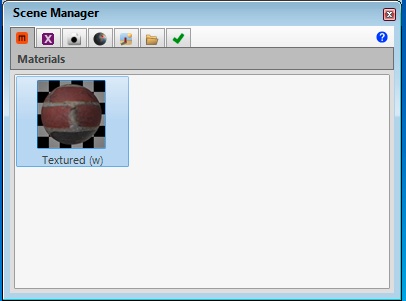
Now double-click on the brick to get to the "Material Editor". Select "BSDF" under the the title "Base".
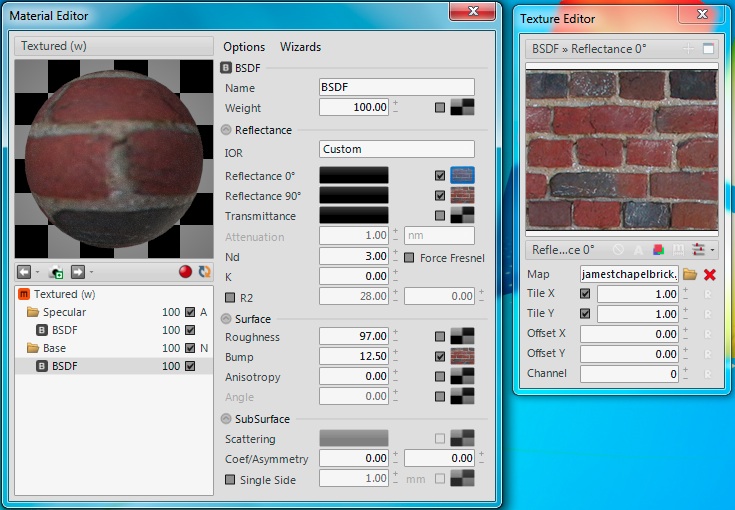
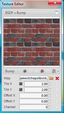
Note that there are two alternative settings for controlling how the texture map is applied to any given object in Rhino. The default setup is to determine the number of tiles that fit to any surface. In the window above. the number of tiles is given at "Tile X" = 1 and "Tile Y" = 1, thus creating single tile on each surface to which it has been applied. If we change these numbers to 2 and 2, then essentialy there would be four such images applied to each surface. For consistency, this should be done for the map adjacent to "Reflectance 0", for the map adjacent to "Reflectance 90", and for the map adjacent to "Bump"through the Texture Editor.
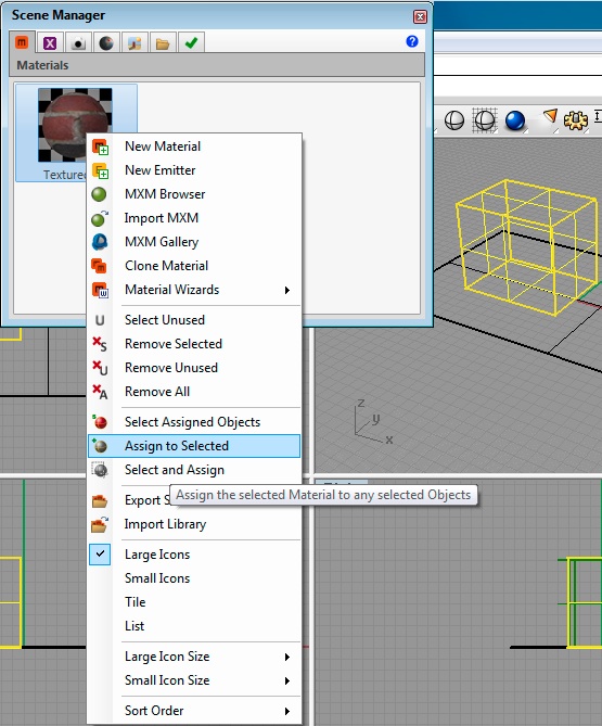
Having completed this adjustments, right-click on the brick material in the "Scene Manager" dialog box, and use the "Assign ti Selected" operator to assign the brick to the cube inside Rhino.
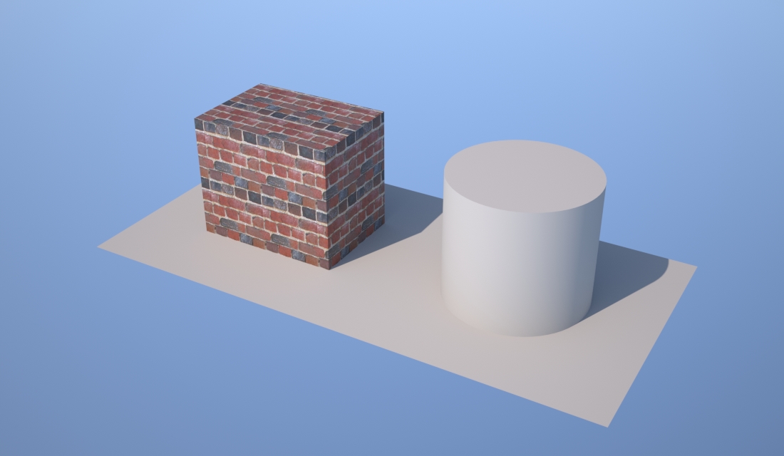
If now rendered in Maxwell, the cube appears as follows:
Or, the option exists to change to the second scheme, one based upon real scale rather than a specified number of tiles per surface. To do this, select the symbol "m" on the right-hand side of the dialog box and just below the image for the material. Note that now the Tile X and Tile Y numerical value system now refers to 2 x 2 meters, the measurment unit upon which this is based. For consistency, this also needs to be done for the map settings for Reflectance 90 and Bump. The sample size changes accordingly.

Moreover, the resulting rendering also changes the relative scale of the brick.
Moreover, note that our default texture mapping method isn't well suited to the block. Brick on the side are in vertical rather than horizontial courses. To correct this in Rhino, we go to the object properties of the block, select "Texture" and the radio button labelled "custom", and adjust the texture mapping option to surface.
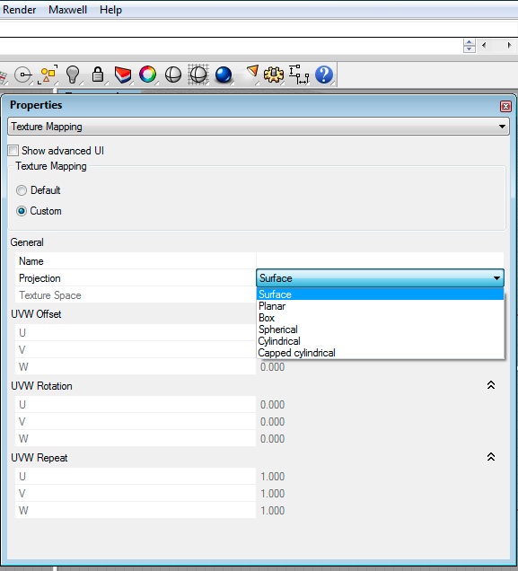
The resulting rendering is as follows:

Make a new material with the same brick texture map. Apply the cylinder mapping technique to the cylinder, disable real scale, set the tiling in x and y to 4.0 x 1.5 for each of reflectance 90, reflectance 0, and bump, similar to what was done above, and get the following result.
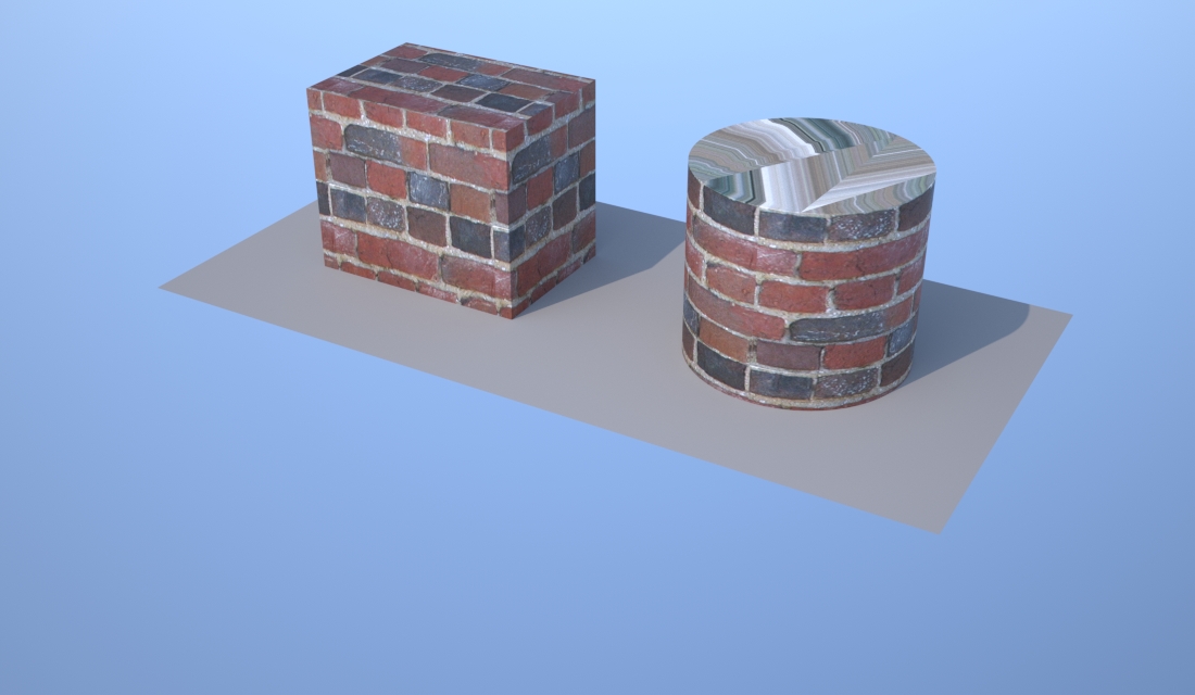
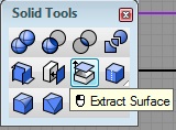
Note that the top of the cylinder isn't being mapped appropriately. Here, depending upon the details of the construction of the cylinder, a number of options may be feasible. One strategy is to separate out the top of the cylinder from the rest of it, and to apply a separate texture map to it. Within the solid modeling palette of Rhino, select the Extract Surface tool, select the top surface of the cylinder and hit the enter key.
Create a new planar texture map to be applied to the extracted cylinder top, turn on real scale, adjust the size parameters to 2 x 2 in x and y for each of reflectance 90, reflectance 0, and bump, for the cube, cylinder and the cylinder top, then the result is as follows:
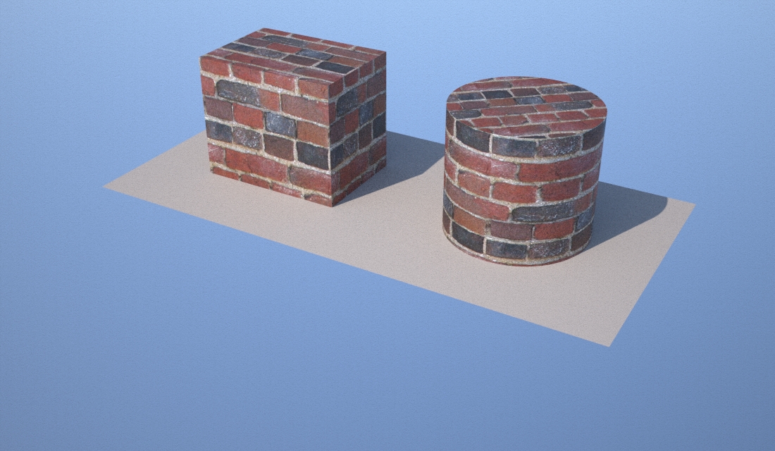
However, the result was less than satisfying since the scale of the bricks is too small. We need to adjust the map to an appropriate scale. Disabling the "real scale" option within the material editor for the top of the cylinder initiates this process. Next, select the surface of the cylinder top again, and under the properties tool, select "Texture Mapping". Finally, change the projection type to "Box" and select the "Equalize Button". Render the model again and you will likely obtain the following result:
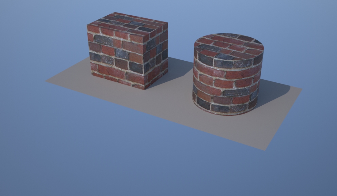
In terms of real world application, the tops of both of the objects above would need to be treated with greater nuance. Bricks would not be set within the top of either the cube or cylinder in the way just described. More adjustments to scale and texture offset values (offset is available in both Rhino's texture mapping tool as well as through Maxwell.).
Within Rhino, use the Object Properties/Plugin tab to also control the scale of the material relative to the object, with values for "x", "y", and "z" establishing the scale separately along each axis in 3D space.
With respect to the methods we've undertaken in this class, the primary advantage of rendering in Maxwell is the immediacy of the plugin to directly rendering the model in Rhino, the convenience of not having to build a separate materials palette in separate modeling environment, and not having to import files into a third-party CAD product (Micostation Luxology). The greatest difficulty is in performance / rendering times and controlling the texture maps to a point of faithful representation. It is often very time consuming to establish an orientation for texture mapping that works and takes much trial an error.
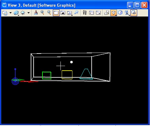
Part 2: Perspective Control and Visualization
1. Controlling Perspective: One aspect of 3D visualization more carefully developed than we have explored thus far is availble through the "Define Camera" tool in Micostation. Here we will examine how to work through some aspects of camera position, angle and projection. (Notes forthcoming.)
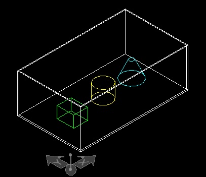
- In Solids Modeling within Rhino, create a still-life of Platonic
objects
- Create a large solid box as a simple room. Put other objects -
pyramids, ellipsoids, spheres, polyhedra, etc. into it.
- Create a set of wall-like Solids..
- Place a new Slab Solid on the top, snapping to corner points to make
a roof again.
- Import into Microstation and save to the dgn format.
- Go to
the front view
- Stretch into a perspective (quick) - you already know how to do this.
- Now change the camera lens. Normal - Telephoto - Extra Wide - Dynamic
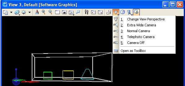
- Return
to Normal Camera
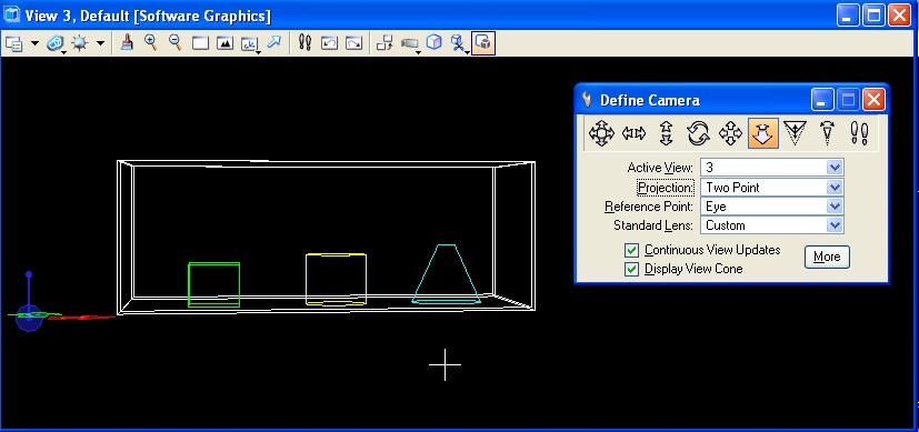
- Go The Visualization Tools Task(left hand side)
- Open Define Camera Tool (E2)
- Make sure Display View Cone and Continuous View Updates are checked on
- Zoom out in the other three windows to see the view cone
- Choose Pan Left and Right (Second Tool in options) - click in the
window and move the mouse to pan
- Choose Pan Up and Down - click and move mouse to pan
- Choose Dolly Forward and Back (6th option tool) - click and move
mouse to move in and out
- Choose Lens View Angle (8th option tool) - click and move the mouse
to zoom the camera's lens.
- Click More button. Expand Camera Position. Set Eye Pt and Target Pt Z
elevation to 5 (feet). Quick way to establish proper elevation
- Fit view in each of the four views
- Notice the View Cone and the white dots indicating viewing angle, eye
point, and target point.
- Manipulate these points. Watch the perspective view change as a
result.
2. Clipping Plane and Saved Views
- Go to
View Attributes drop down (top left of perspective window)
- Check Clip Front and Clip Back
- Look in perspective view now and you will see part of the model
cropped away.
- Look in the view cone - there is a new line and control dot
representing the section plane. Move it and watch the section cut move
in the perspective window.
- Set it to a location that you like
- Find the Utilities/Saved Views drop down from the top tool bar (the
same tool we used for saving animation view).
- Choose the Two-Hands icon to capture your view.
- Give it a name in the settings dialog that appears, then click in the
perspective window to save it. A balloon will pop up indicating it is
saved.
- Rotate and zoom to a different view.
- Go back to the Saved Views drop down and double click the named view
you just saved. Your view will return to this state.