COMPUTER
AIDED
ARCHITECTURAL DESIGN
Workshop 6
Notes,
Week of September 30, 2012
INTRODUCTION TO LIGHTING AND RENDERING
These notes will introduce basic lighting and rendering through Rhino and continue on to more advanced options using the Rhino plugin for Maxwell.
PART 1. LIGHTING
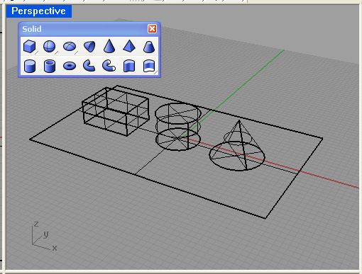
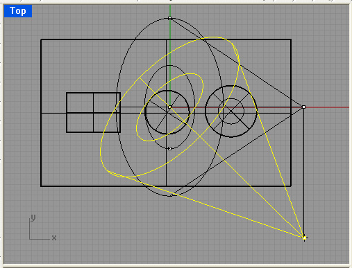
1. Create a Rhino Model with a ground plane surface and three solids as follows:
2. Open the lighitng icon from upper right-hand side of screen.
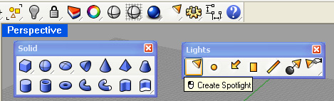
3. Place a spot light in the model from the front view, entering the target and radius first, and then the light location second.
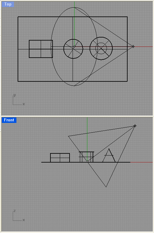
4. Turn on the planar lock. Select the light and turn the control points to on.
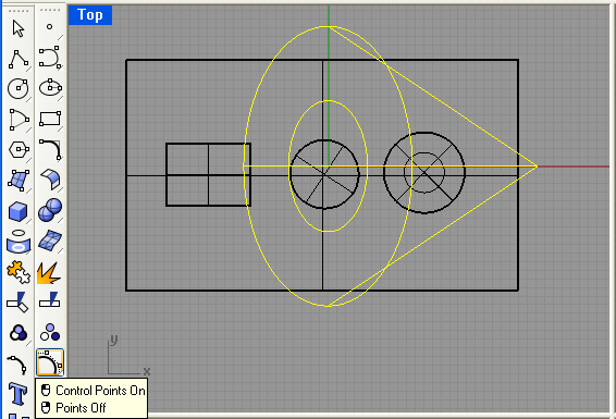
5. From the top view, move the lighting source position to the +x, -y position relative to the ground plane.
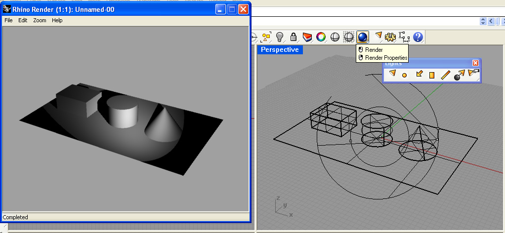
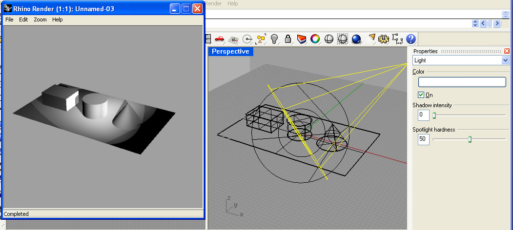
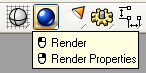
5. Activate the perspective window, select the rendering icon, and render the view.
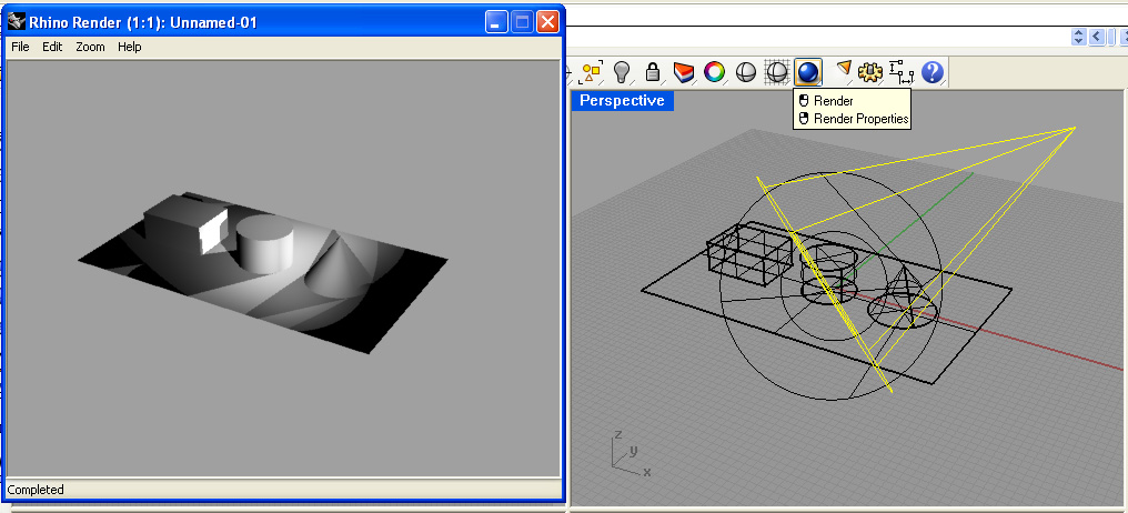
6. Following a similar procedure, create a back spot light pointing towards the center of the model and create a rendering.
 7.
7.
7. Select the properties icon for the back light and reduce the shadow intensity to 0.
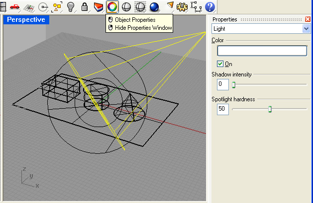
8. Render the perspective window again and note that the second light is no longer casting a shadow.
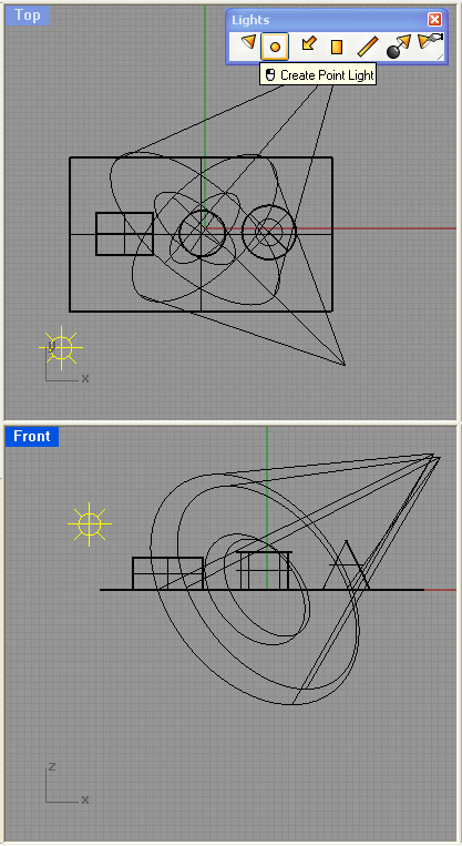
9. Add a point light to the upper left hand corner of the model. Here it is only necessary to position the light source. Begin in the front view and continue to place the light in the top view similar to setting the light source lcoation for the spot light.
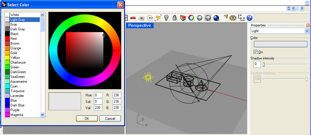
10. Using the properties icon, adjust the shadow intensity of the point light to 0 and the color to gray.
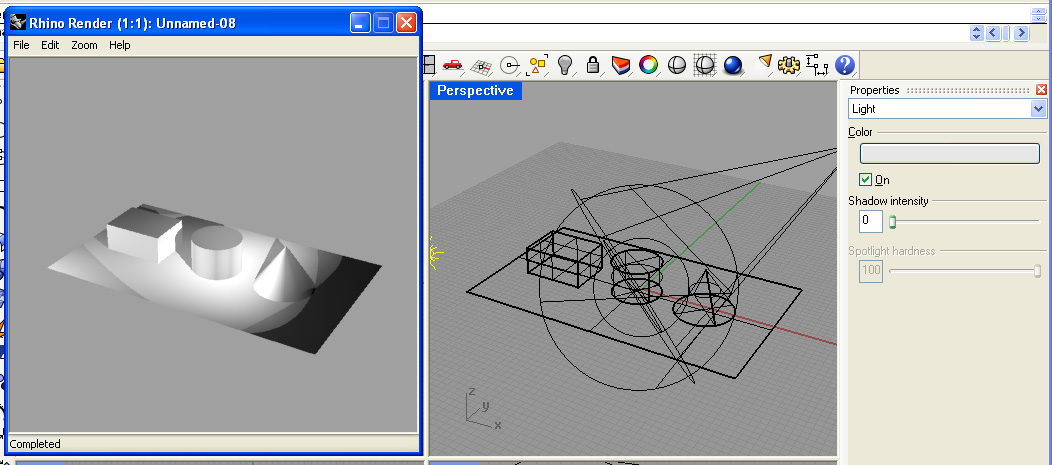
11. Render the perspective again for a rough simulation of three points lighting.
12. Note that the edges of the geometry running diagonally across the rendering are jagged, such as on the cone and the box.. This is due to aliasing. To correct for this, open up the render properties dialog.
PART 2. RENDERING
1. Within the render properties dial box, set the antialiasing to high and the screen resolution to 1024 x 768 pixels.
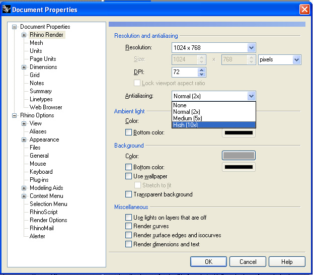
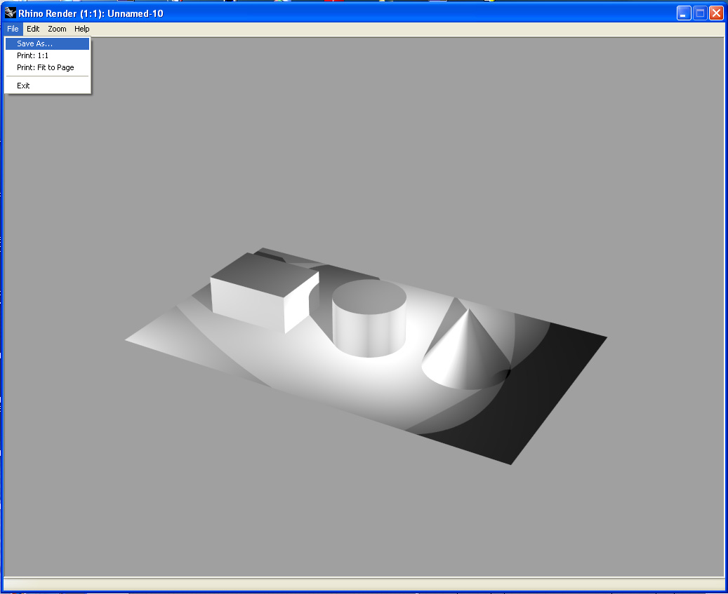
2. Render the perspective view and note the anti-aliasing effect as well as the image size. From within the Rhino Render window, use the File/Save As Option to save the rendeirng to a jpg or tif image.
3. You can continue to adjust the antialiasing level by rendering the same modeling within a more advanced rendeing tool as we will see in a later tutorial.
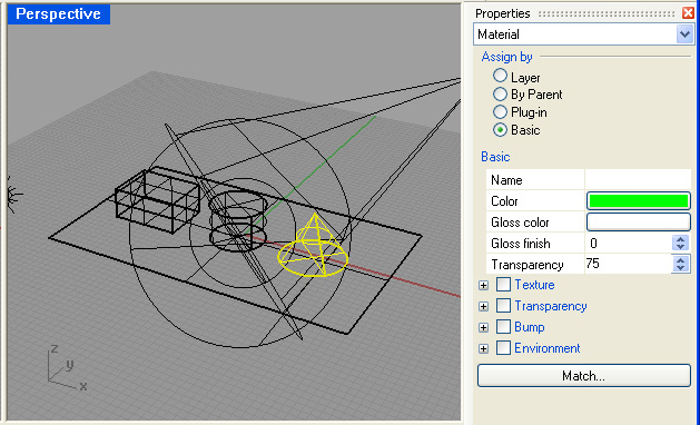
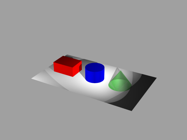
4. Using the same properties icon as before, set the material colors of the box, cylinder and cone to red, blue and green, and also make the cone transparent. Note that the "Material" pull-down tab is active, that the "basic" assign by method is selected, and that for the cone, the transparency value is set to 0.75. Do not sleect the "Transparency Check Box" which refers to a separate material property.
5. Rendering the view to 640 by 480 pixel resolution results in the following jpg file.
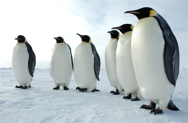
6. Download the image of penguins below by right clicking on it and saving it to your local working folder.
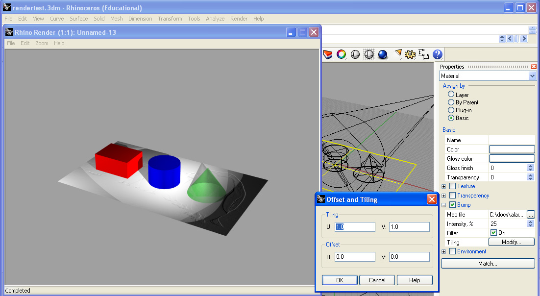
7. Now select the ground rectangle, open up the properties dialog, select the check-box for "Bump" and also select the "+" symbol for "Bump". Load the file above through the map file interface. Adjust the "tiling" to 1 by 1, and render.
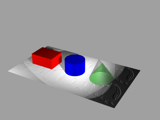
8. Within the same dialog box, adjust the tiling to 2 x 2 , increase the intensity to 75 %, adjust the gloss finish to 50, and re-render.
PART 3: LIGHTING AND RENDERING WITH MAXWELL
Part 3 includes a short description of rendering techniques via the Maxwell Plugin. This is an alternative option to Luxology. However, we will be exploring Luxology in greater depth with respect to the description of materials as well as animaiton techniques. We will then return to Mawell for comparative techniques and values.
For a complete treatment of Maxwell's plugin to Rhino see the Maxwell For Rhino Plugin Manual
1. Go to Menu
item Render> Current Render>Maxwell For Rhino
2. Go to Menu item Maxwell/Plugin Windows>Scene Manager
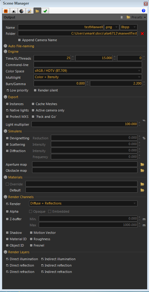
3. Go to Folder Tab
Set Name to testMaxwell.png
Set folder to local folder on "T" drive (or on your local "C" hard drive on a private computer)
Set time to "25" and SL to "15"
Set Light Multilight to "Intensity"("Color + Intensity" is no longer an option)
Set engine to "low priority"
Set render to "difffuse + reflections"
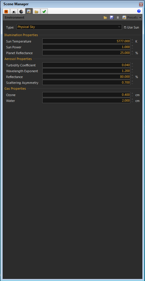
4. Go to Environment Tab
Set type to "Physical Sky"
Select on "Physical Sun"
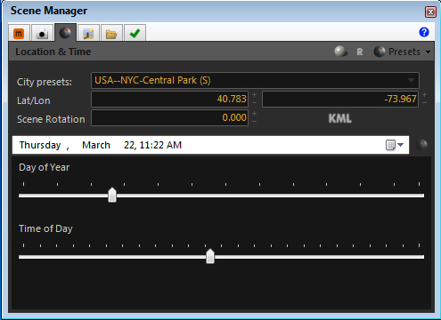
5. Go to Location and Time Tab
Set location to desired place.
Set time to 11 a.m..
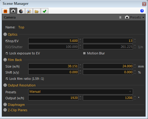
6. Go to camera tab.
Change output resolution to "manual"
Enter output width as 1920 (height will change proportionately). We will modify this later.
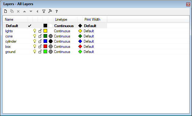
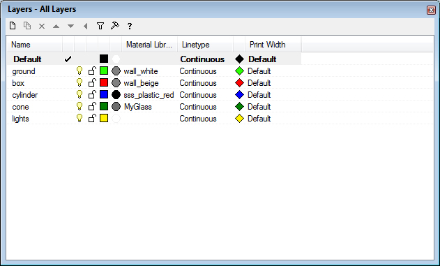
7. Create layers for ground, box, cylinder, sphere and lights and copy objects to each one, changing layer color as desired.
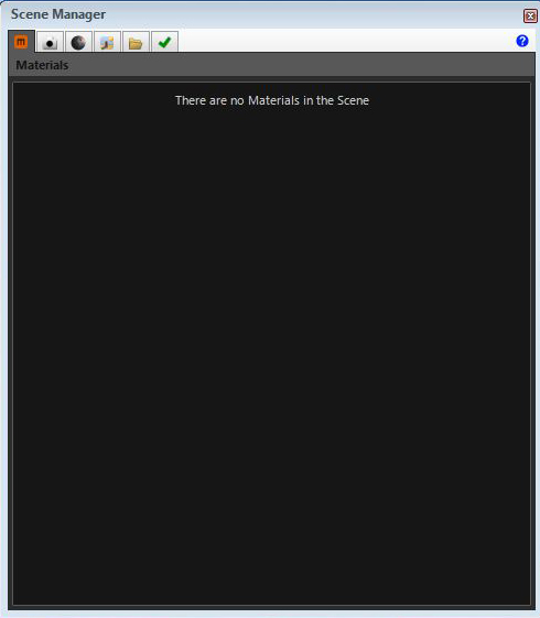
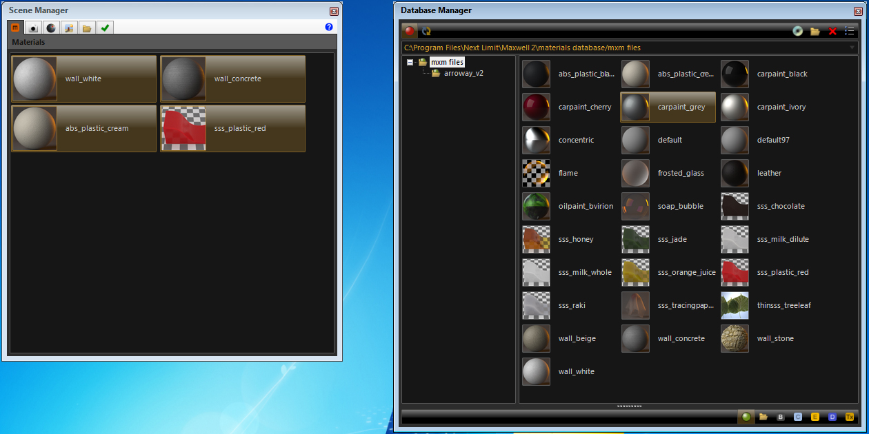
8. Go to materials tab.
Note: the tab is (still) empty. No materials are yet defined for Maxwell.
9. Go to Menu item "Maxwell>Plugin Manager>Database"
Drag desired materials from Database manager to Scene Manager
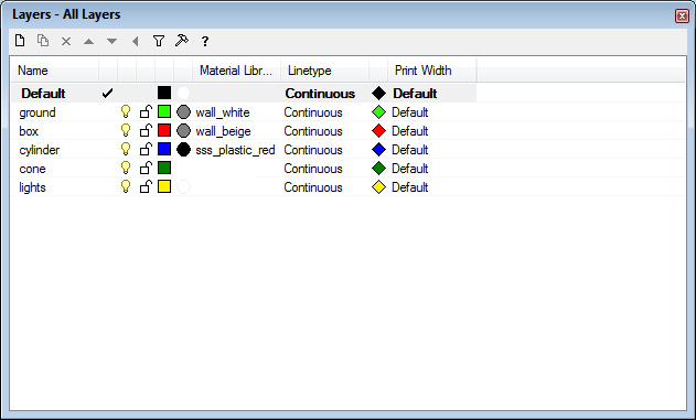
10. In layer manager, go to default material column.
Go to the Material Editor and choose Assign by "plug-in ", and select a Maxwell material via the "browse" option. Note that the "projects" folder on the "classes" server (\\archstore01.arch.virginia.edu) also includes a number of downloaded or student created Maxwell materials.
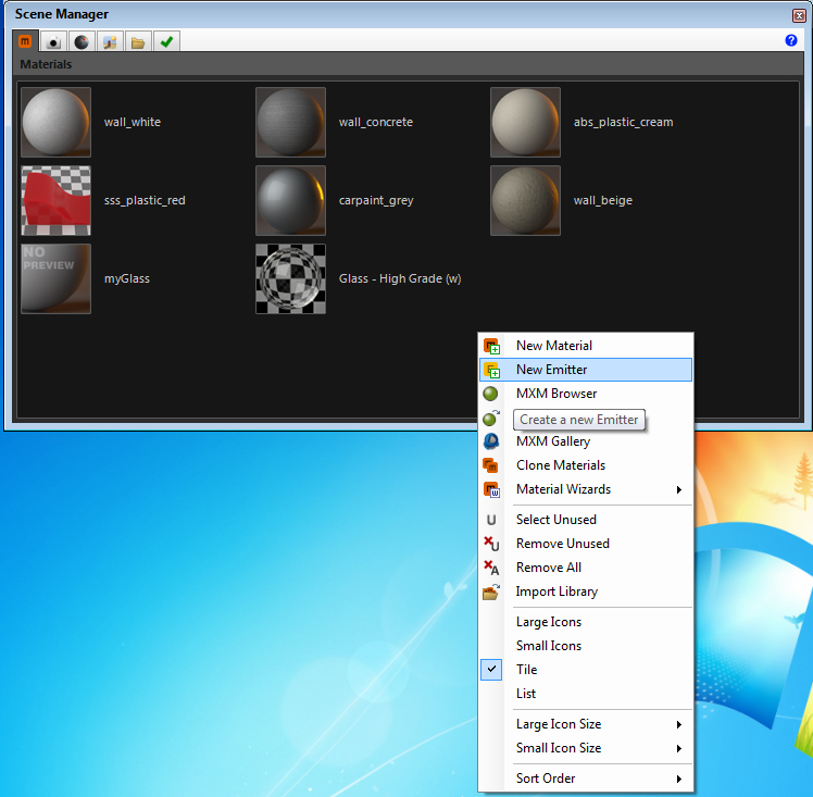
Repeat step for all remaining objects except the cone. For the cone, go to the Materials tab and create a new material using a wizard for glass:
Right-click in the materials window to create a new material.
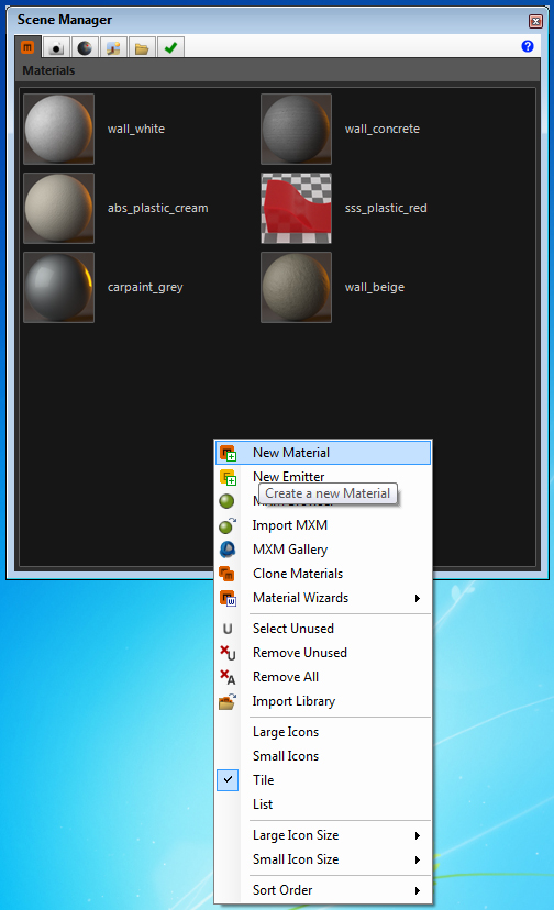
Double-click on the new material.
Name the material "myGlass" - Select the "Wizards" menu and choose "glass/ hight grade".
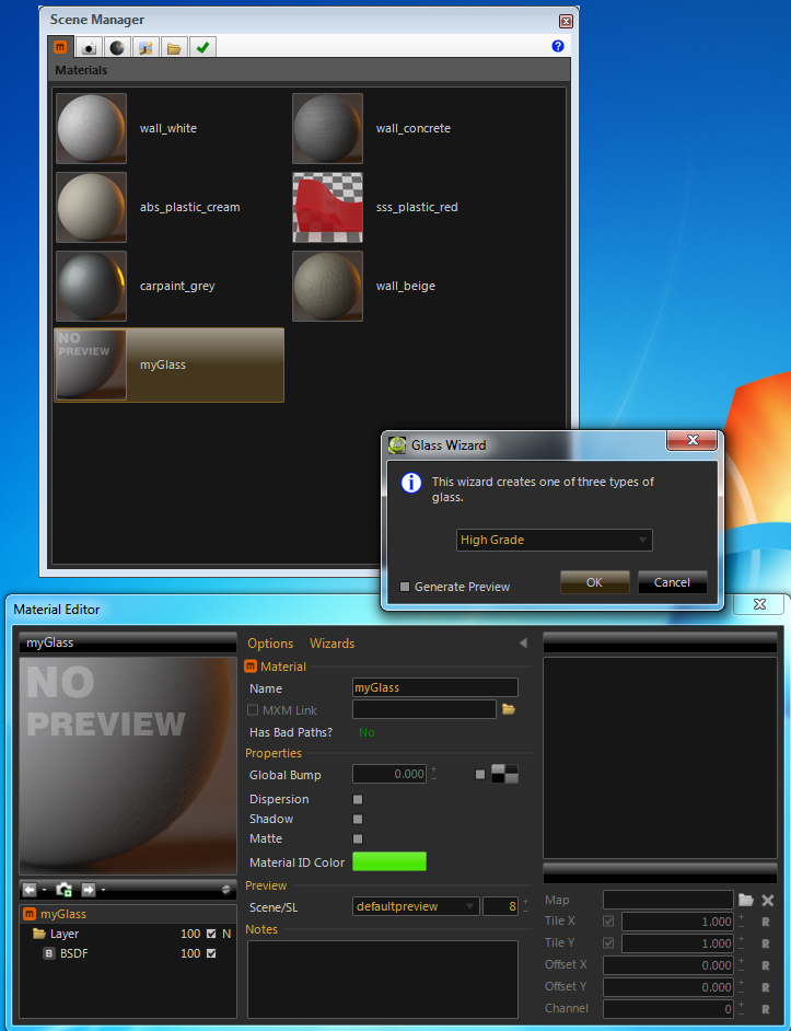
Adjust material properties
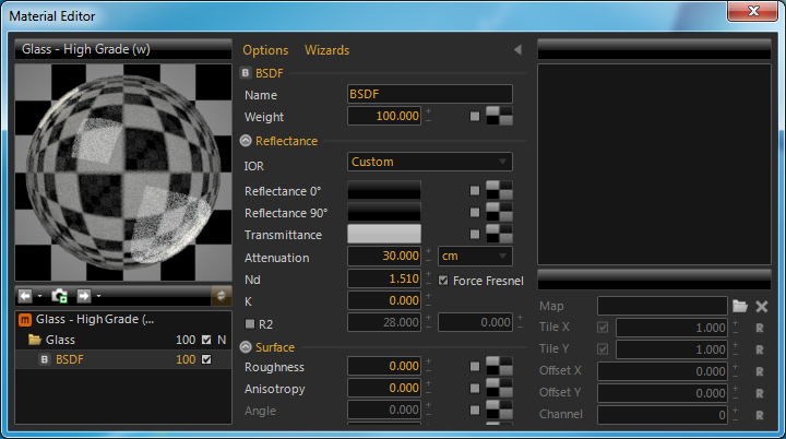
Note Nd = index of refraction - a measure of the speed of light in a material
k = extinction of the wave - absorbtion loss (optional)
More detail on these properties:
http://support.nextlimit.com/display/maxwelldocs/Index+of+Refraction+-+ND+and+K
http://support.nextlimit.com/display/maxwelldocs/Surface+Properties
Apply glass material to sphere layer.
11. Select "render" and render scene in maxWell
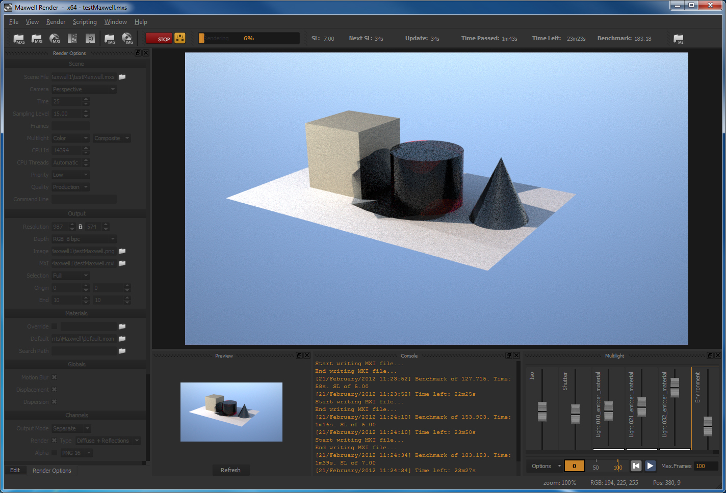
12. Stop "render" change to"camera" tab.
Adjust "resolution"
Re-render and adjust Iso and "shutter-speed"
13.
Go to Multilight tab
Adjust lights as well as sun, etc.. while rendering
14. Go to Material Editor, and create emitter and call it
"myEmitter1"
Select wattage and other properties.
15. Go back to Rhino. Edit light properties. And assign
emitter to key spot lght via layer option or directly.
16. Note IES (Illuminating Engineering Society) options.
Used in defined emitter in Rhino plugin for Maxwell.
Lighting
Fixture Data and Examples
Additional notes
1. Maxwell notes,
helpful to preparing this outline, prepared by Alex D'Aversa
2. Rendering Farming Setup
with Maxwell (IT staff notes).