COMPUTER AIDED ARCHITECTURAL DESIGN
Workshop 2 Notes, Week of September 9, 2013
Graphics Primitives Continued, Symmetry Operations, Modify and Select Tools
1. PRIMITIVES REVIEW
Primitives consist of basic elements such as lines, circles, arcs, boxes, etc.
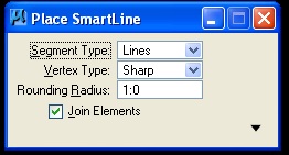
Primitive tools typically have dialog boxes associated with them to
control the method of primitive creation (ie. a circle by edge, center,
or diameter, copy, etc.). Remember to use these dialog boxes to control
the ways in which your tools are working. The dialog for "Place
SmartLine" appears below.
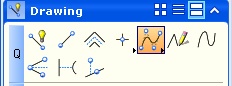
2. TOOL BOX ORGANIZATION
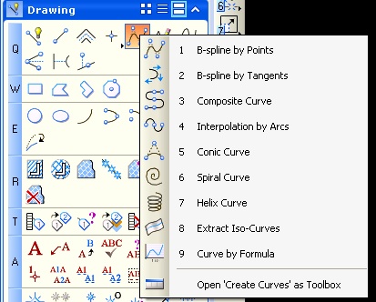
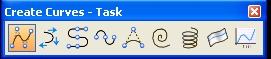
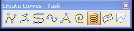
Within the tool bar, additional sub tools can be accessed by holding down the left mouse button on any tool icon with a triangle in the lower left hand corner. For example, by selecting "Open 'Create Curves' as Toolbox" in the menu above, a sub-tool palette below can be pulled out and displayed as its own tool bar as well.
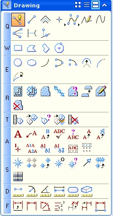
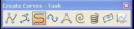
3. CURVES
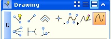
Point or Stream Curve: [7th tool in the DawingTask menu] This is a line based, simple curve that is very quick, but does not provide a lot of control or exact geometrical specification. On the other hand, the Create Curves B-Spline curves tool is obtained from 5th icon in Drawing Task menu and is more precise.
B-Spline Curves : [DawingTask Menu/ Create Curves Menu/Place B-spline Curve (highlighted icon in above menu)].
Note several methods available under this curve type:
Method 1: "Control Pts" where the curve is drawn by points which appear
to attract the curve (similar to a kind of gravitational pull),
where all but the end points don't lie on the curve. This will
create a fairly smooth curve.
Method 2: "Through Pts" where the curve is drawn by points which
are directly in the path
of the curve. This will create a closer fitting curve to specific
points. However, this results in a curve that is typically less
smooth than the Control Pts curve.
Bezier Curves : [DawingTask Menu/ Create Curves
Menu/Place Composite Curve (3rd icon in Create Curves menu highlighted
above)].
Mode: WIth Bezier Curves, thecurve is defined by tangential lines. The
length pf the tangent lines effects their impact on the curve.
OBSERVATION: When constructing a curve, don’t
just trace a drawing. Work to figure out the geometric elements most
descriptive of the design. This may help you to more completely
understand the geometrical order of the design, and later optimize on
finding a more advanced and appropriate technology to use (i.e. Helix
tool
for the Guggenheim ![]() ). That is, test varied type curves to substantively work
through the goeometrical composition.
). That is, test varied type curves to substantively work
through the goeometrical composition.
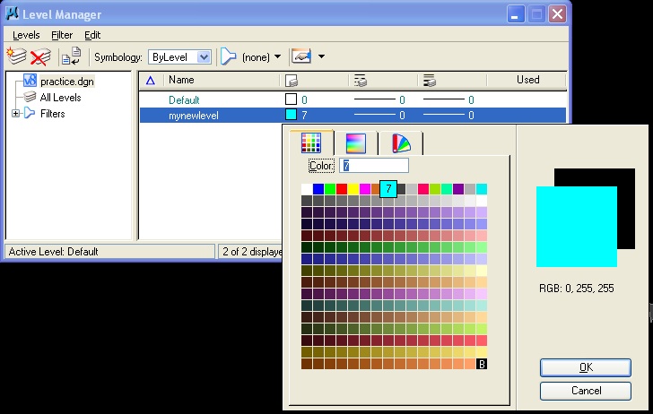
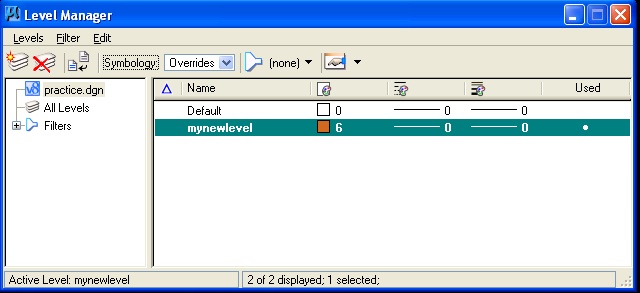
4. LEVELS (aka LAYERS in other programs)
![]()
Levels are created by either clicking on the level manager tool (icon above) centered at the top of the Microstation window, or selecting the menu item "settings/level / manager. By best practice, each level in Microstation should be given an independent color so as to be able to more easily understand the organization of drawing. To begin, create a new level for each different type element of your drawing (e.g, walls, roof, etc..). Work this way from the outset in order to keep in place an ongoing conceptual framework of the organization of your model. It may be that you will adjust this framework as your model develops or as new ways of parsing your project occur to you..
![]()
The active level can be changed more conveniently by selecting it in an abbreviated level manager tool box (showing the level "walls" in the figure above) also located at the top of the application windows.
A. Within the more complete settings/level manager dialog box, to activate a level:
B. Within the settings/level manager dialog box, to create a level:
C. Color can be displayed on objects in three
different ways:
3.1 Set the display to the ByLevel symbology option in the Level Manager dialog box (see captured image above) and note:
- If you draw an object in any directly assigned color (i.e., yellow)
- then the new object appears in that color (i.e., yellow, not cyan)
- Conversely, if you draw an object in the "bylevel" color
- then the new object appears as cyan.
3.2 Alternatively, in the Level Menager dialog box, adjacent to the word Symbology, choose "Symbology: Overrides" and pick yet another color for "mynewlevel", such as orange (we didn't cover this example in the workshop).
Here, the override color will force all objects are on a particular level to inherit the overrides color. To display this color, you also need to turn on a unique attribute in the view attributes window.
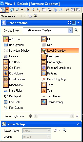
3.3. Furthermore, in conjunction with 3.2, you also need to do the following:
- From the Settings menu, choose View Attributes (or press <ctrl-B>).
or, In the view window control bar, select the View Attributes icon in the upper left-hand corner by means of a downward-pointing triangle- The View Attributes dialog box opens as depicted below.
- Turn on "Level Overrrides" option as depicted below.
- if you do steps 3.2 and 3.3, then all elements on the level (i.e., including the yellow and cyan elements) are forced (overridden) to appear as orange.
5. Edit select by attributes/toggle general button
Select
Mode
5. OBJECT SNAP TOOLS
Bring up the snap tool palette - button bar
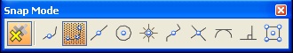
Snap shortcuts
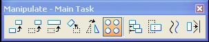
6. SYMMETRY TOOLS (Move, Rotate, Mirror, Scale)
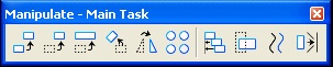
![]() Copy element. Method: type in # of copies in dialog box if more than
one copy is desired at the same distance from one another.
Copy element. Method: type in # of copies in dialog box if more than
one copy is desired at the same distance from one another.
![]() Move element tool is vector based and can be translated from a point
not within the object being modified. Click on or outside element once
it’s selected and move in desired direction, typing in distance
in Accudraw if you like. The Move element tool can be used with copies
and with repititions by selecting the appropriate options in the dialog
box.
Move element tool is vector based and can be translated from a point
not within the object being modified. Click on or outside element once
it’s selected and move in desired direction, typing in distance
in Accudraw if you like. The Move element tool can be used with copies
and with repititions by selecting the appropriate options in the dialog
box.
![]() Move/Copy parallel tool moves complex figures
by segment maintaining the relationship of the parts.
Move/Copy parallel tool moves complex figures
by segment maintaining the relationship of the parts.
![]() Scale tool can be used with numeric input or the three
point method. This tool can also be used with repetitions.
Scale tool can be used with numeric input or the three
point method. This tool can also be used with repetitions.
![]() Rotate tool can also be used with copies and repitition. To rotate an
object to a specific angle, type the angle number in the dialog box
after selecting the object to rotate.
Rotate tool can also be used with copies and repitition. To rotate an
object to a specific angle, type the angle number in the dialog box
after selecting the object to rotate.
![]() Mirror tool can be used to make an exact mirrored copy of
a desired object along a selected axis.
Mirror tool can be used to make an exact mirrored copy of
a desired object along a selected axis.
(see array tool in 7 below)
Make sure to pay attention to the instruction prompts located in the bottom left corner of the screen for the specific usage steps of each tool.
7. SOME CURVES
Archimedes and Logarithmic Spiral (7th tool from left)
Orient rectangle to a bspline curve
Apply array tool with "Along a path" option and specify number of copies.
8. MODIFY TOOLS

![]() Modify element. This very generic and useful tool can be used to alter
a primitive multiple ways, including: a point (by clicking on a point),
an edge (by clicking on a midpoint of a segment) or size of an element
(by clicking on a point of a circle, box, etc.).
Modify element. This very generic and useful tool can be used to alter
a primitive multiple ways, including: a point (by clicking on a point),
an edge (by clicking on a midpoint of a segment) or size of an element
(by clicking on a point of a circle, box, etc.).
![]() Delete part of an element breaks an element
into two separate pieces and deletes a part of an element.
Delete part of an element breaks an element
into two separate pieces and deletes a part of an element.
![]() Break a selected element at a point.
Break a selected element at a point.
![]() Extend line extends a line. There is also an
option to type in the distance of the resulting length.
Extend line extends a line. There is also an
option to type in the distance of the resulting length.
![]() Extend two elements to intersection extends
two lines to each other
Extend two elements to intersection extends
two lines to each other
![]() Extend element to intersection extends one
line to another, or to an implied intersection.
Extend element to intersection extends one
line to another, or to an implied intersection.
![]() Trim element cuts one object. Option:
pre-select two elements with the control button to cut another.
Trim element cuts one object. Option:
pre-select two elements with the control button to cut another.
![]() Intellitrim is more complicated than the regular trim element, which
works in most cases. It combines defining area to trim into the tool.
Intellitrim is more complicated than the regular trim element, which
works in most cases. It combines defining area to trim into the tool.
![]() Insert vertex
Insert vertex
![]() Delete Vertex
Delete Vertex
![]() Circular Fillet
Circular Fillet
![]() Construct Chamfer
Construct Chamfer
9. SELECTION / PRE-SELECTION
You can pre-select before using other tools to alter more than one element at a time.
a. ![]() Using arrow (aka element selection) tool,
click and drag to make a rectangle around the things you want to
select.
Using arrow (aka element selection) tool,
click and drag to make a rectangle around the things you want to
select.
b. ![]() Use arrow tool to click on individual elements, holding
ALT button to add to your selections.
Use arrow tool to click on individual elements, holding
ALT button to add to your selections.
c. ![]() Use power selector (arrow with light bulb). Offers different methods
(areas), modes ( add/subtract from selected elements), or click on
arrow at bottom of box to select by colors, element type, levels, etc.
{technique "c" not covered in workshop
Use power selector (arrow with light bulb). Offers different methods
(areas), modes ( add/subtract from selected elements), or click on
arrow at bottom of box to select by colors, element type, levels, etc.
{technique "c" not covered in workshop