1. Glass and Transparency: How can you control the level of transparency for glass?
Creating glass typically involves a diffuse layer, a reflection layer and a refraction layer. However, for window glass, the use of a refraction layer may not be needed. The the key to controlling transparency is by controlling parameters in the diffuse and reflective layer as follows:
For example, create four planar surfaces above a ground plane surface, a V-Ray sun, a neutral gray and a light gray material, and render as follows: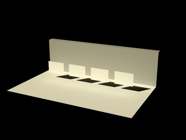
For the first (left-most surface) create a VRay material with defaulted values for a diffuse layer, reflection layer and a refraction layer. Select the transparency color on the diffuse layer, and adjust its value to middle gray.
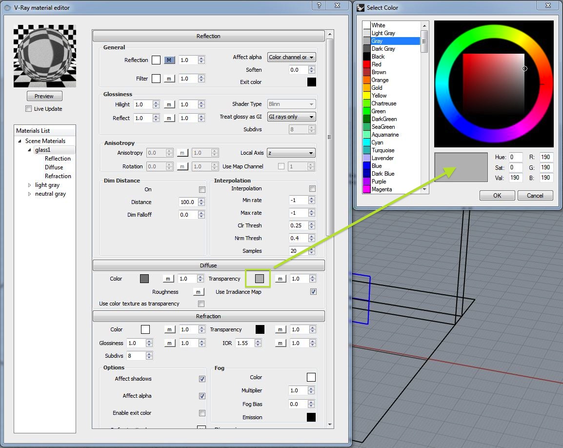
Apply the material to the left-most blue rectangle, re-render, and note that reflectivity is relatively high, but the level of transparency is barely apparent.
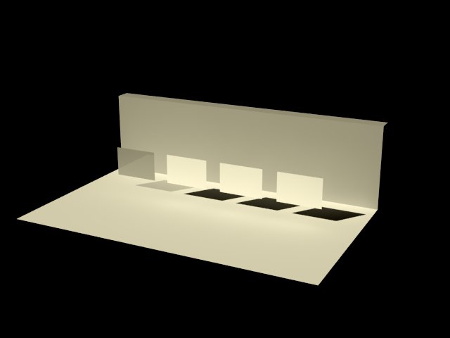
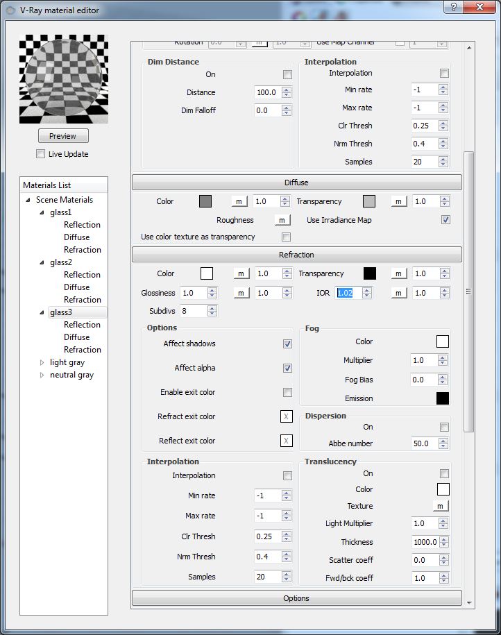
Now return to the material editor, duplicate glass1, and on the refraction layer of glass2, adjust the value of IOR to 1.1.
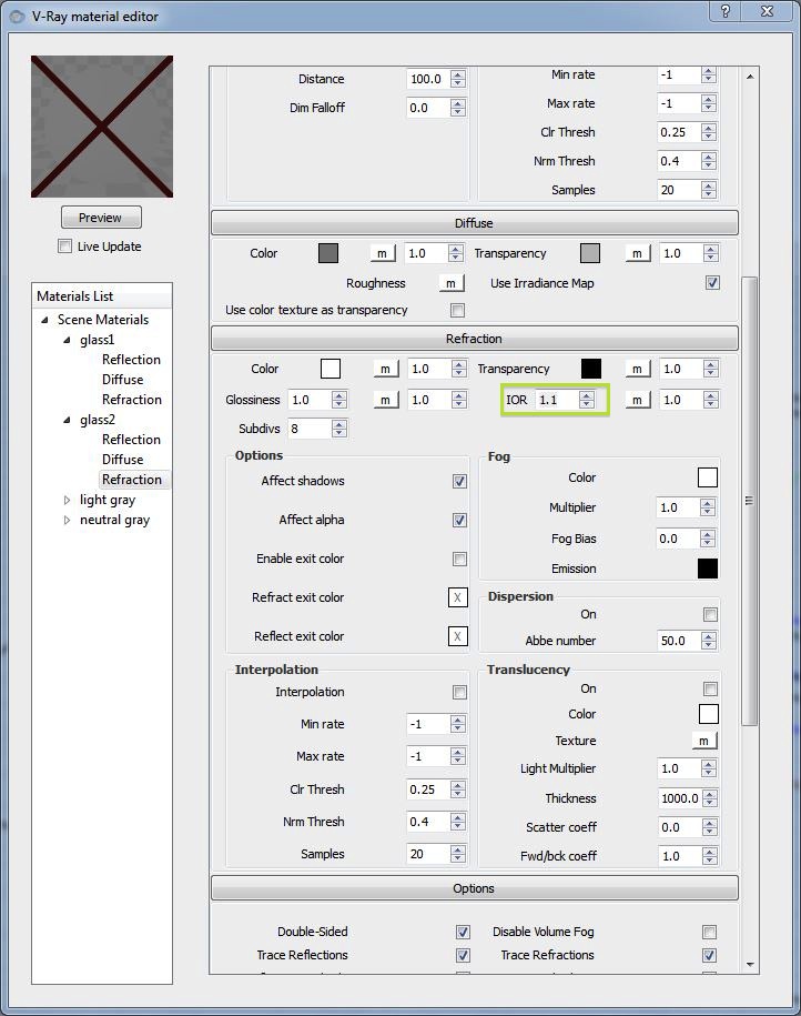
Apply the material to the second rectangle from the left-hand side and re-render.
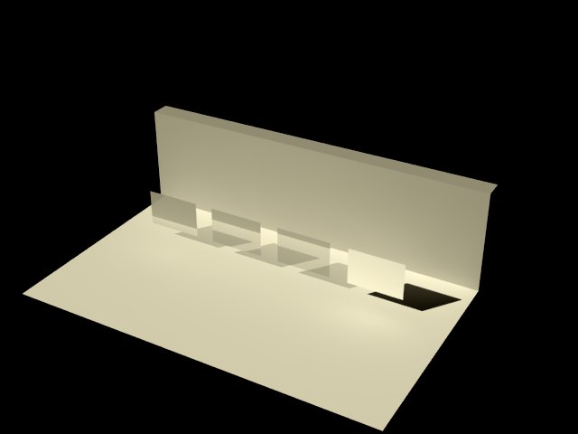
Now, duplicate the glass2 to a new material glass3, and adjust the refraction layer to an IOR of 1.02.
Apply to the third rectangle and note the less distortion of the shadow and vertical surface behind the glass.
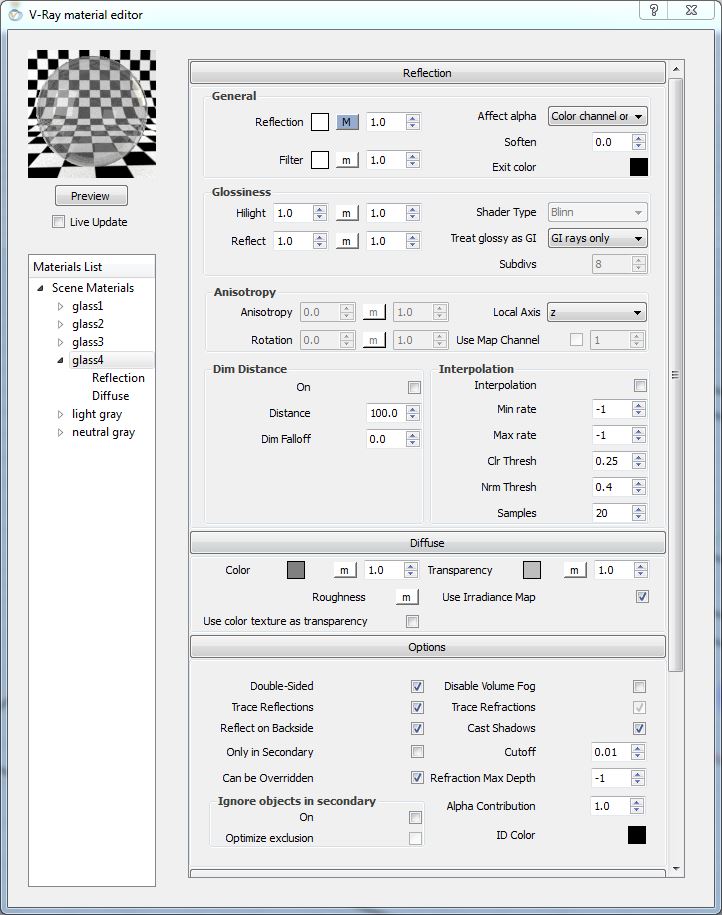
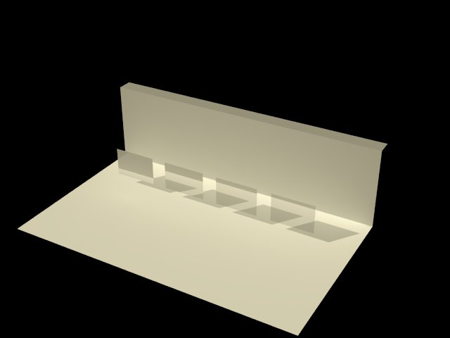
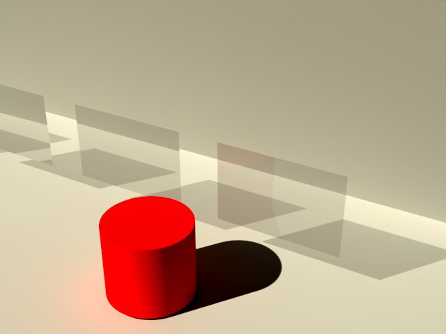
Duplicate the material to a new material glass 4 and remove the refraction layer.
Re-render the model and note fewer distortions.
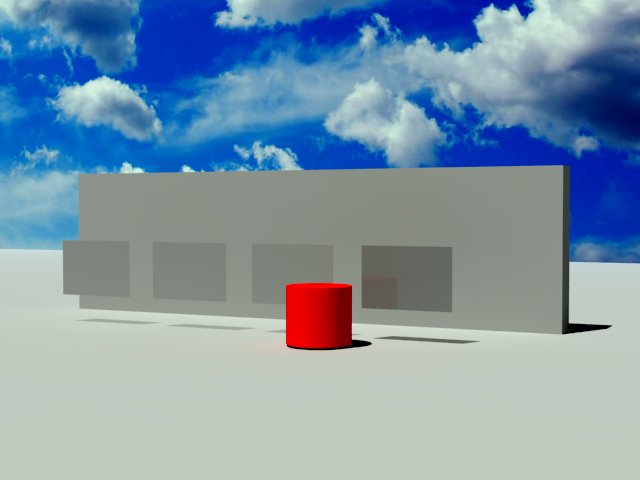
Create a diffuse red material, use it to add a red object to the foreground, and note the very slight reflection in glass panel four.
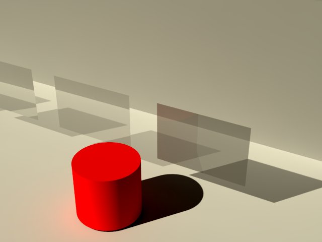
However, return to the transparency property of the diffuse layer for the material, and decrease it from a neutral to a dark gray (thus decreasing transparency):
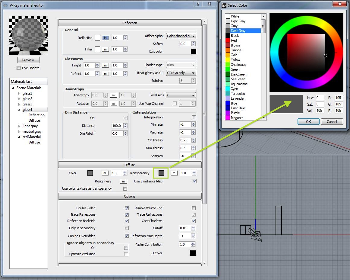
Note that this change results in a slighlty greater degree of apparent reflection:
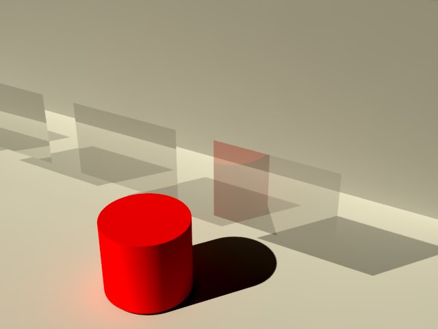
On the other hand, restore the transparency value of the diffuse layer to neutral gray, and increase the reflection to 4.0 as in the following dialog box.

Note that the red object is reflected more intensively in a rendering that results from this adjustment.
2. Environmental Sky: How do you generate the sky (revisited) and what is the workaround if the sky doesn't render?
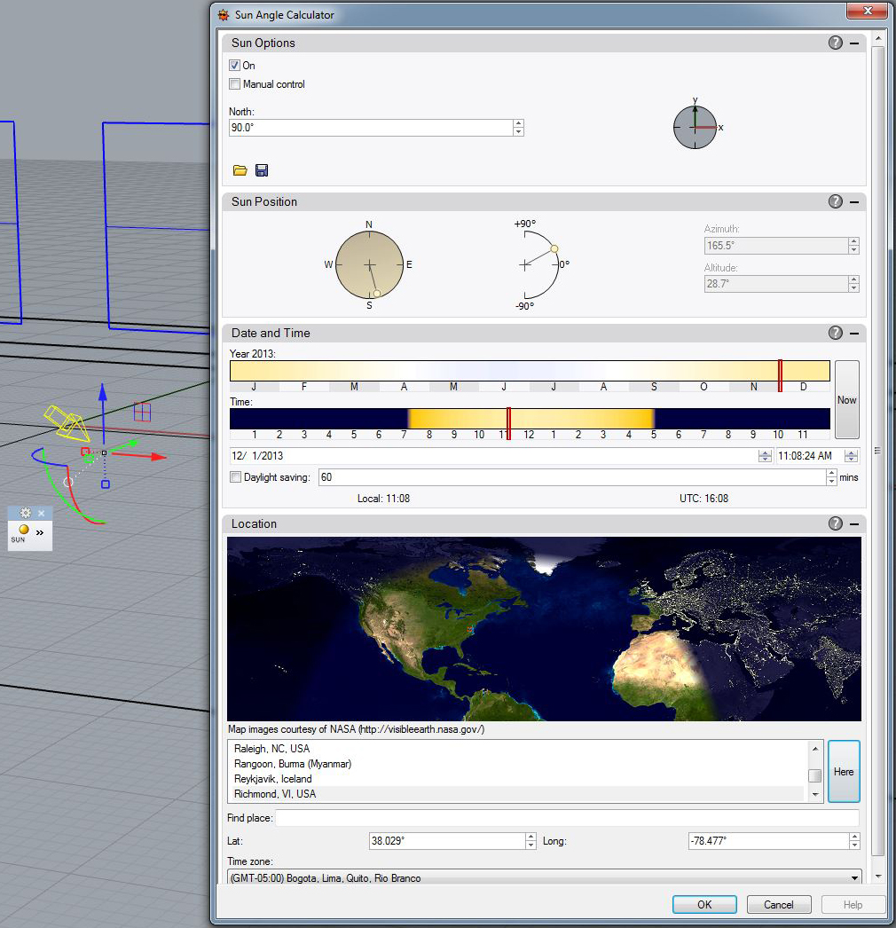
To create an environmental sky requires two key techniques, per workshop notes 6, part 3:2.1 Build a V-Ray Sun
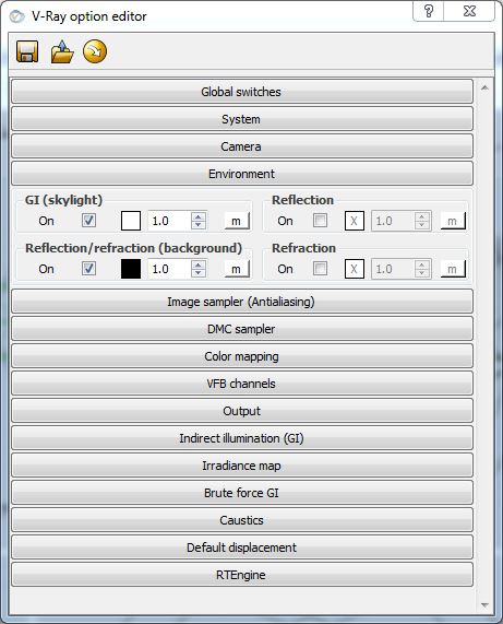
2.2 Go the V-Ray option Editor, Open the "Environment Tab" and adjust the "Reflection/Refraction (background)"
Return to the V Ray Options Panel and open the "Environment" tab.
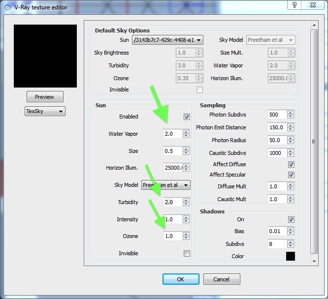
Select the letter "m" adjacent to reflection, and within the V-Ray texture editor, change the texture to "TexSky", pick the hexidecimal number for the V-Ray sky, adjust values for "Water Vapor" to 2.0, "Turbitity" to 2.0, and "Ozone" to 1.0, and then select the OK button.
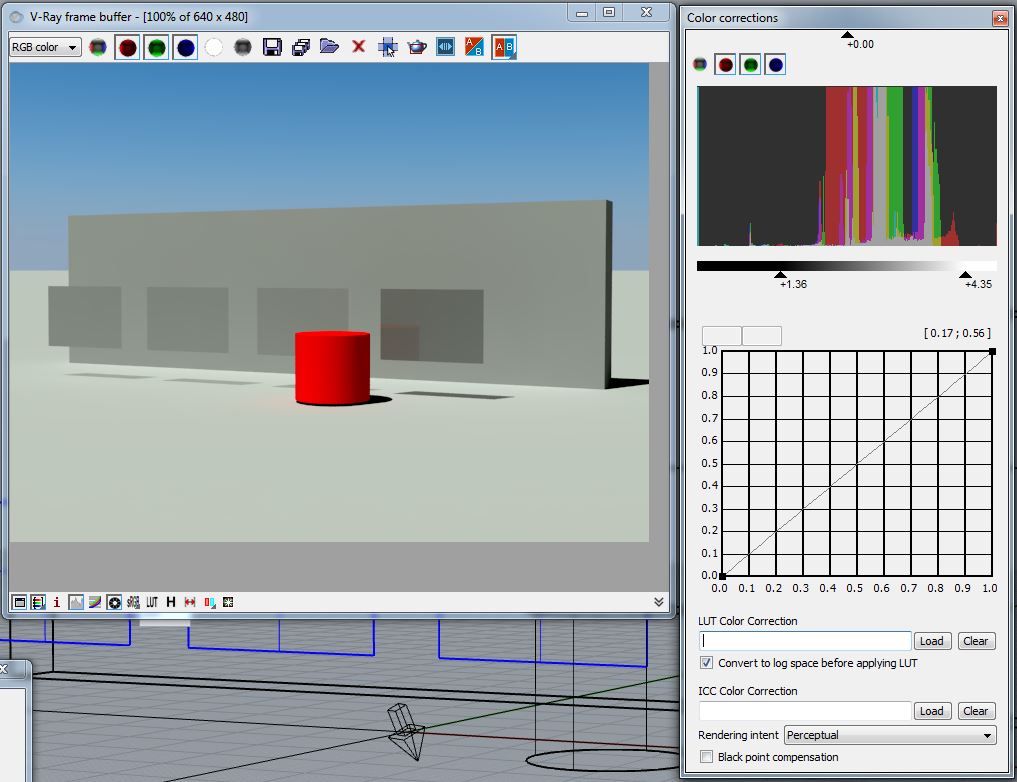
2.3 It also typically requires that you use the "Color corrections" window to adjust exposure level and contrast range, per workshop 6, to see the sky directly.
2.4 If, after following the steps 2.1 through 3.13, the sky isn't visible, then you may as a last resort try the following:
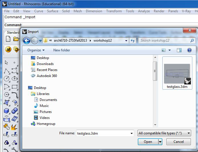
Open an new Rhino file, go to the menu item file/import and import the pre-exisiting Rhino file.
Remake the V-Ray sun (if not already existing), and repeat steps 2.1 through 2.4.
3. Background Texture Maps: How do you map a background image for rendering without using Photoshop?
There are several methods to create background texture maps, apart from using Photoshop. A good source of background images is:http://blenderartists.org
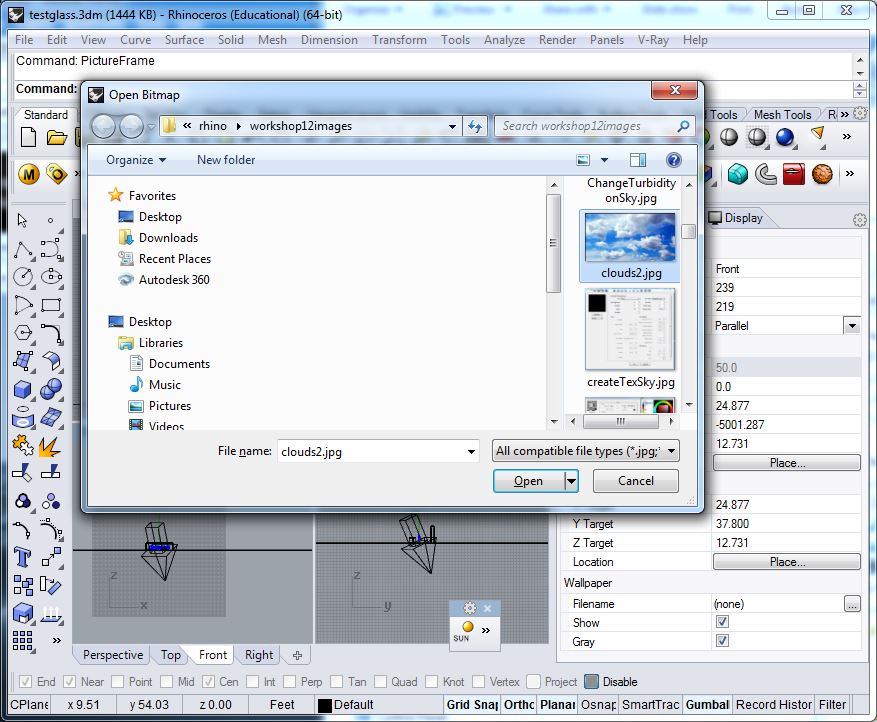
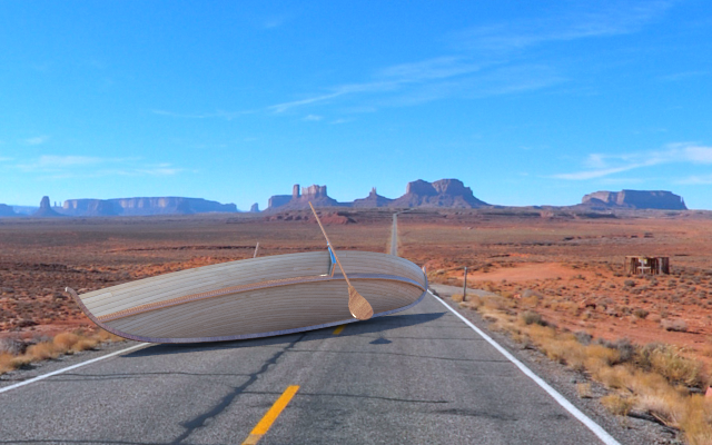
3.1. The first and one of the most effective methods is to use the "PictureFrame"command with an appropriate image file, and rotate it to fill out the perspective camera used to render the image. For example, select the front view window, at the command prompt type in "PictureFrame", and load a background sky image:
Within the front view draw the picture frame, and then using all the views rotate and move the picture plane to fit the perspective camera.
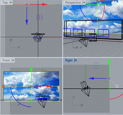
The perspective view will render as follows:
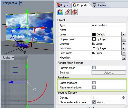
Note: To avoid shadows being cast by the picture frame itself, select the picture frame, go to the properties tab and turn off the "Casts Shadows" and "Receives Shadows" attributes:
3.2 A separate technique engages the use of the "Reflection/refraction (background") map in the V Ray Options Environment tab.
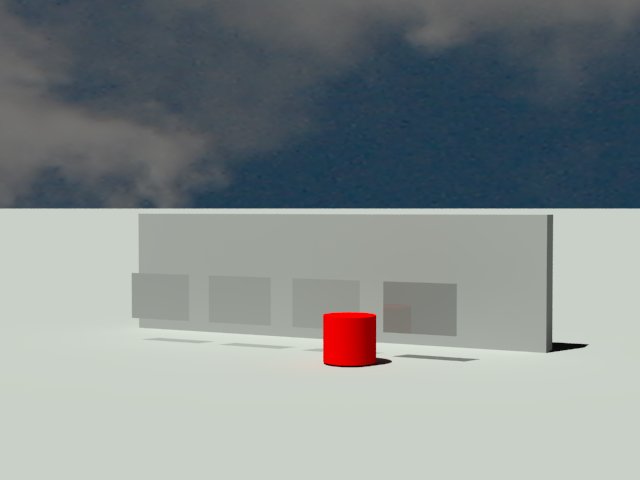
We initiate this example with a rectangle example of clouds.

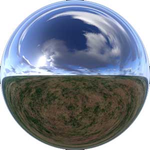
We then try the same technical with a spherical image obtained from thehttp://blenderartists.org web site referenced above for a more effective outcome:
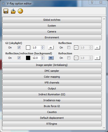
Within the "Reflection/tefraction (background)" setting you will likely need to increase the numerical value to some value above 1.0 to ensure that the background image is bright enough to be visible. In this example the value is set to 7.0.
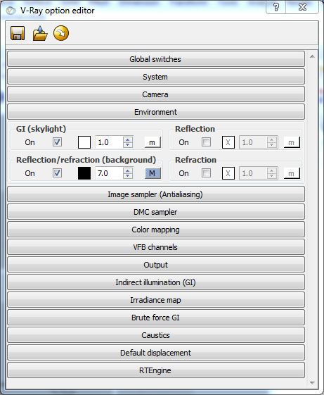
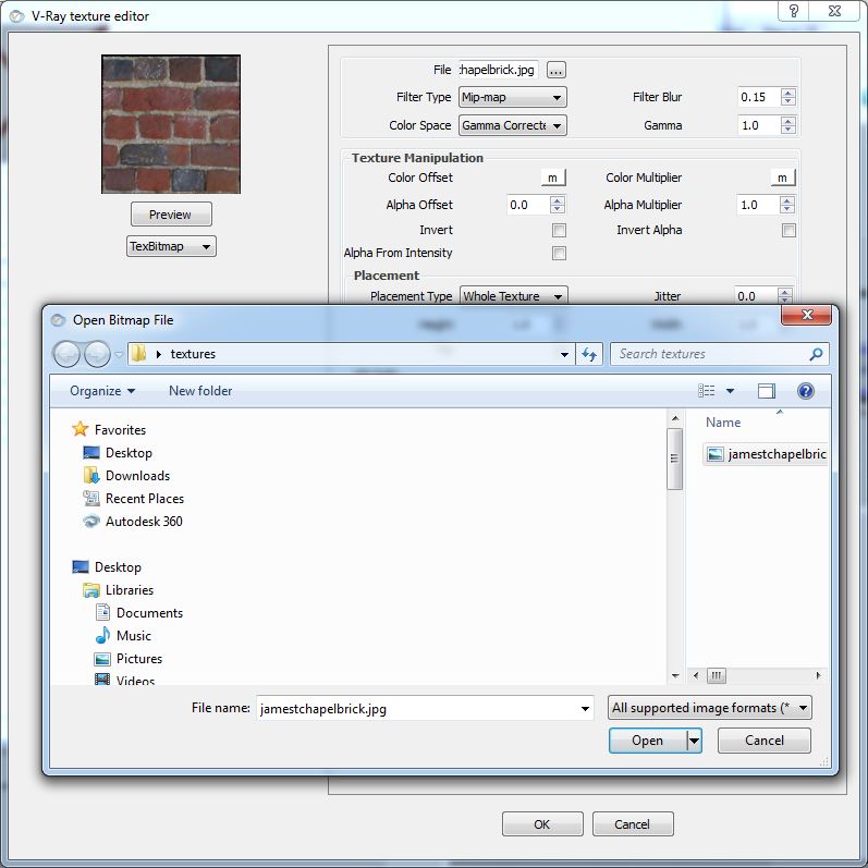
Select the letter "M" adjacent to "Reflection/refraction(background) , and then within the V-Ray texture editor choose the "TexBitMap" option and select the background image:
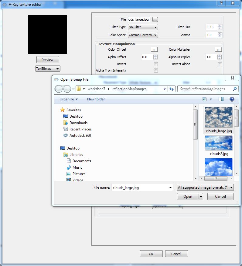
Change the setting for "UVW Type" to "UVWGenEnvironment" and "Mapping Type" to "Spherical" at the bottom of the dialog box as shown in the image below.

Hit the OK button in the dialog box and render the image. Adjust the numerical value for brightness of the "Reflection/refraction (background)" by trial and error - we set it's value to 7.0 at the beginning of step 3.2. The background sky effect from the rectangular source image is only partially successful. Most of the image isn't show due to the spherical mapping.
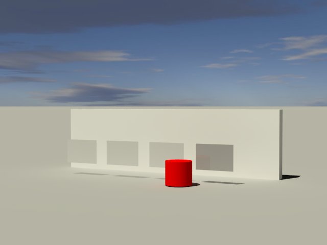
Go back to the "Environment" tab, and the change "Reflection/refraction (background)" setting to 12.0.
The resulting contrast range for rendering is better, although the sky still appears clipped.
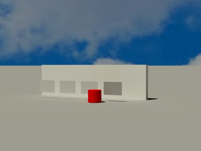
However, when using same technique with the high-resolution spherical image from http://blenderartists.org, the results are more promising.
3.3 A more elaborate method of building a texture map is described in the following tutorial (developed by a former student now in practice). See the tutorial for details:
http://www.lookinglass.us/vray4rhinoWiki/tiki-pagehistory.php?page=Render%20a%20model%20into%20a%20background%20image&preview=6
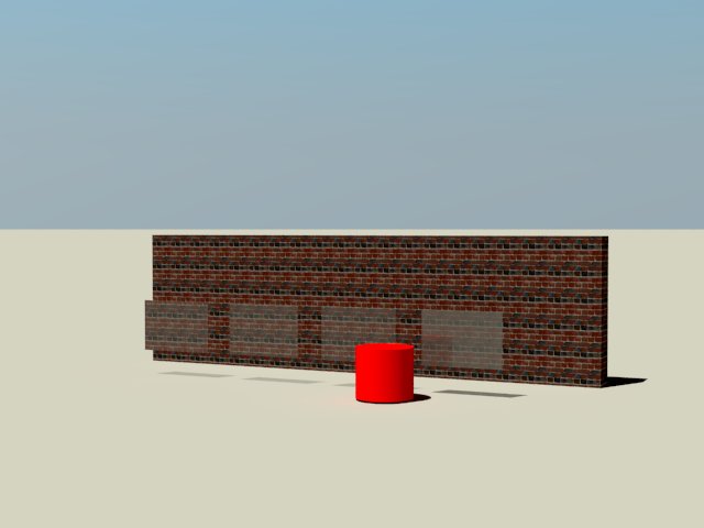
4. Texture Map Pathways: Why isn't my texture map showing up in render view?
1.
When attaching a jpg image to create a material texture map, ensure
that the absolute pathway to the attached file is the same on any
computer. That is, if your texture map is located in
C:/Users/yourID/Desktop/textures/jamestchapelbrick.jpg on the computer
in which it is first attached to a material definition in V-Ray, then
ensure that it is exactly at the same folder location on any computer
in which you plan to work with it.
2. Alternatively, according to V-Ray technical support received on 12.2.13, the easiest way to proceed is to place the texture files in the same folder as the Rhino file. V-Ray automatically looks for texture files in this folder. (I've not fully tested this approach).
5. File Size Reduction: How do you reduce the file size for large geometry files?
1. Use Rhino blocks to create copies of geometry.2. Use texture maps, displacement maps and bump maps rather than full object geometry.
6. Proxy Files: Since RPC files (2 1/2 dimensional texture maps) aren't available in Rhino, what other options exist?
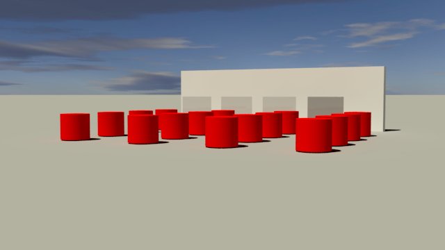
VRay comes with a proprietary option to produce a so-called proxy file. For example, create an array of columns from the red cylinder and render the result in VRay.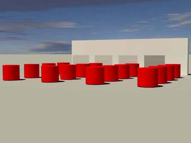
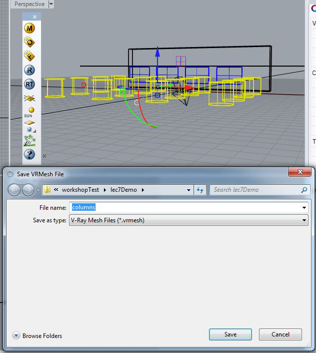
Now, preselect the colums, and right-click on the V Ray proxy icon (resembles green foliage) to write the files to the "vrmesh" format.
Note that the columns within Rhino are automatically converted to a proxy file resulting in different wireframe image..
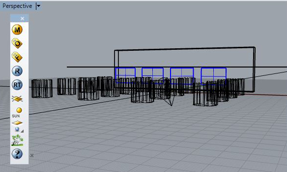
Re-render the image for the same result.

7. Image Resolution: How do determine image resolution?
7.1 Go to the V-Ray Option Editor "Output" tab.7.2 Select one of the preformatted options, or use a customized setting. For example HD lower resolution television is 1280 x 720, and HD higher resolution television is 1920 x 1080.
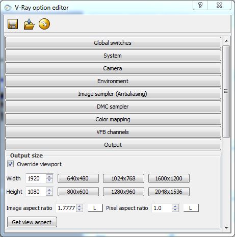
Note that doubling resolution can in effect quadruple rendering times, and so such a higher resolution is only recommended for final renderings. Small postage stamp size renderings, such as 640 x 360 or lower can be used to quickly test files.
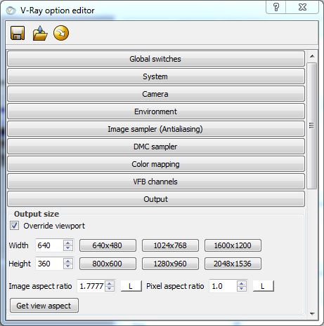
The same aspect ratio is maintained for the lower resolution rendering shown here
in comparison to the higher resolution rendering shown below.
