COMPUTER
AIDED
ARCHITECTURAL DESIGN
Workshop 12
Notes,
Week of October 21, 2013
TEXTURE MAPPING, REAL SCALE AND ADDITIONAL MATERIAL PROPERTIES
These cover cover different kinds of material mapping techniques and control of scale for V-Ray plugin to Rhino in Part I. For comparative purposes, similar techniques used in Maxwell are described in Part II.
Part I: VRay Mapping Techniques
1. Create The Rhino File and Get Some Images of Materials
Create a working folder in your desktop. Open Rhino, create a new Rhino 3dm file in working units of "feet" and save it to to the same folder. Copy the folder from the Classes server "CLASSES\ARCH2710-6710-Mark-FAL2013\examples\materials" to the desktop folder where you have saved the 3dm file.
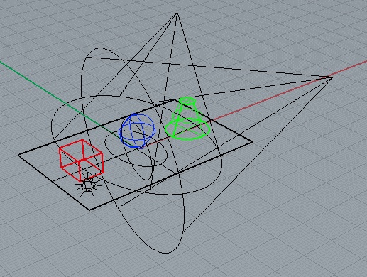
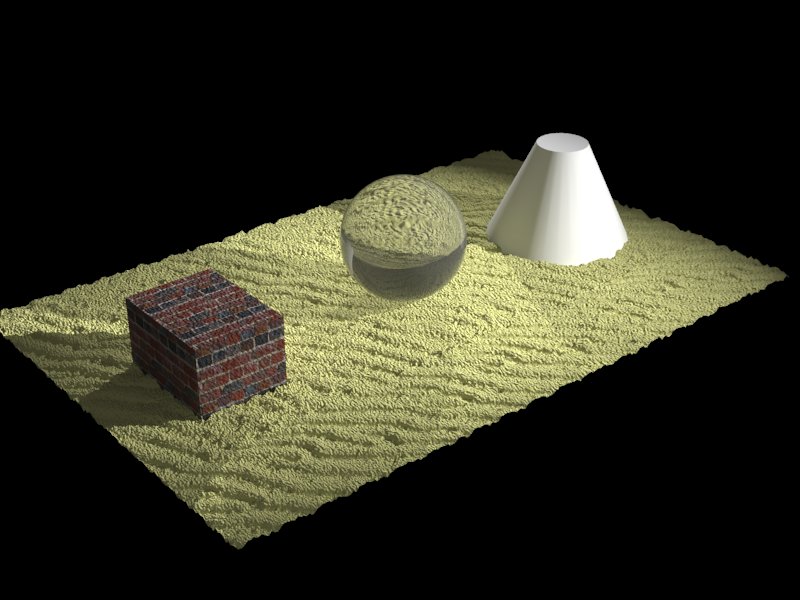
2. Create three objects siting on a surface in the ground plane as in Workshop 6, with each object on its own distinct layer, and with two spot-lights and a point source light as was created for workshop 6.
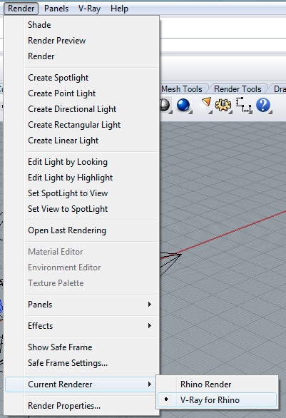
3. Set V Ray as the rendering plugin by going to the menu item Render>Current Renderer > V-Ray for Rhino
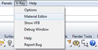
4. To create a brick texture map, go to the menu item V-Ray/Material Editor
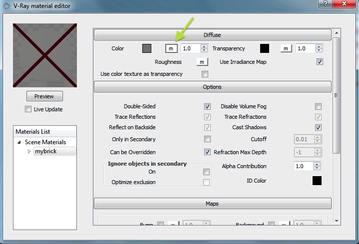
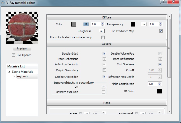
Within the V-Ray/Material Editor, create a "standard" material named "mybrick" per the methods described in workshop 6. Within the Material Editor, select the letter "m" adjacent to the "Color" spefication area of the "Diffuse" tab.
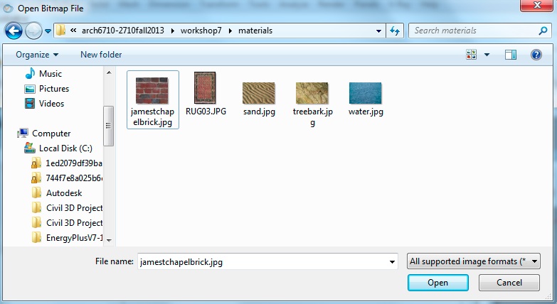
WIthin the "Texture Editor", within the pull-down menu under the preview window, select "texBitmap" and then select the file "jamesstchapelbrick.jpg" from the materials folder created previously.
Now preview the brick within the V-Ray material editor.
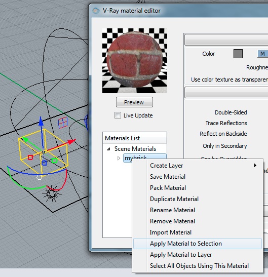
Select the block within the pespective view in rhino, right-click on "my-brick" and select the option"Apply Material to Selection"
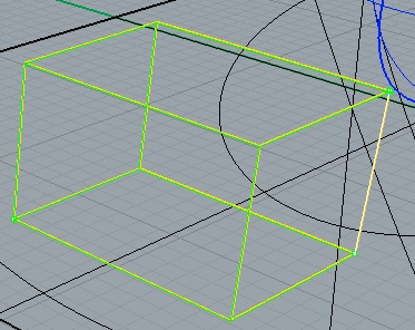
Now go to the properties editor for the block, and select the "Apply Box Mapping" tool.
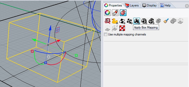
Within Rhino, select opposite corner points on the ground, and an upper corner point to determine the scale of the box mapping.
Now, back with the properties editor, note the XYZ size at 0.783, 1.038 and 0.654 in the case here, which refers to the dimension units (e.g., feet) of the box in the x, y, and z directions.
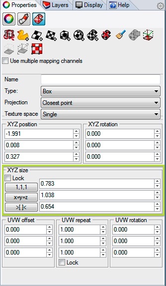
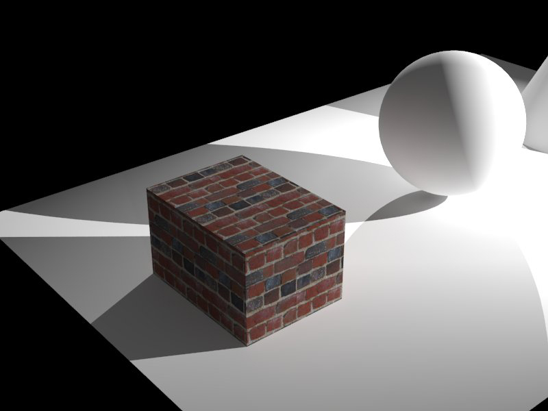
Render the box for a mapping at this scale, and note the entire texture map is scaled to the exact size of the cube, such that the scale of the bricks varies accordingly in each face of the cube.

However, witin the properties editor, adjust XYZ size by entering values of 1.0, 1.0, and 1.0. This establishes that the scale of the brick texture is 1 unit (1 foot) each along each directlion.
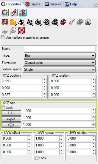
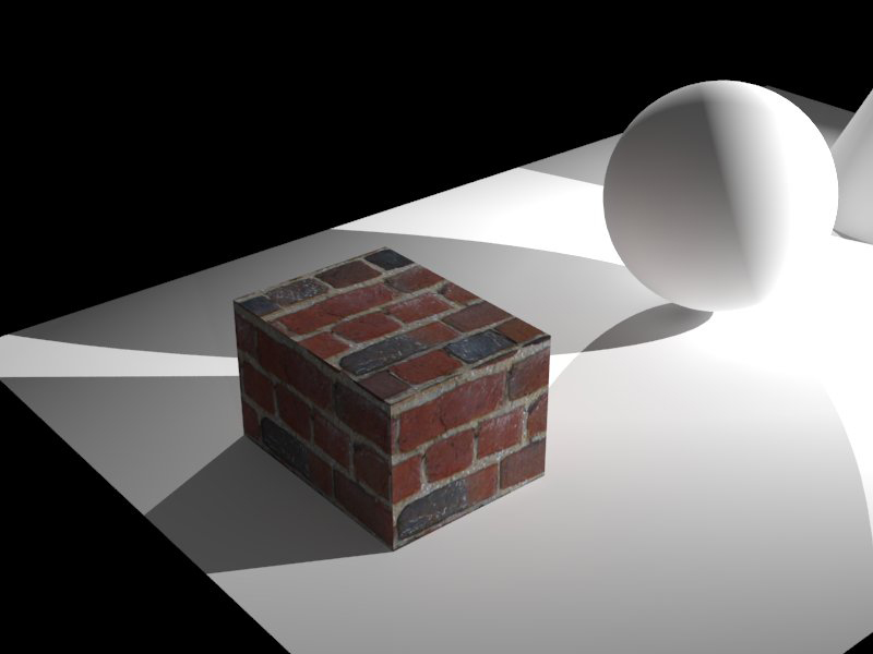
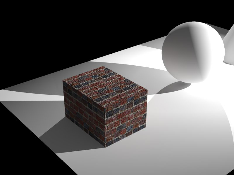
Re-render the cube and note the more uniform size of the the result.
At this point, to repeat the texture map in a tile pattern along each
face of the cube, there are two options:
1. Change the UVW repeat parameters to 2, 2, 2 to double the texture along each face of the cube.
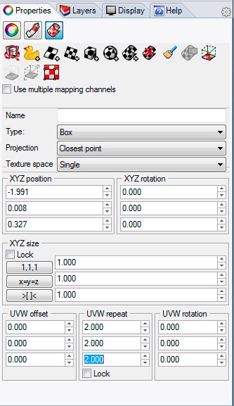
2. Or, change the XYZ size to 0.5, 0.5, 0.5 for a simlar result. Here each tile of the map is at the scale of 0.5 units (i.e., 0.5 ft.) each.
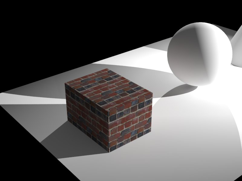
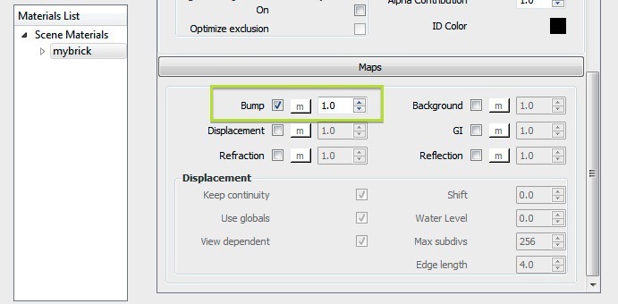
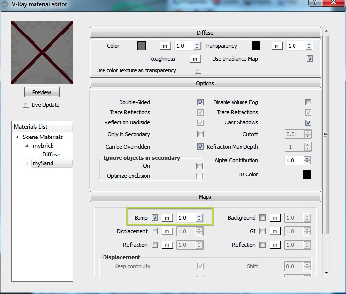
5. To create a slighlty aged look, go back to the V-Ray Material Editor, select "mybrick" go to the maps tab on the brick, and select check-mark for "Bump" and the adjacent letter "m":
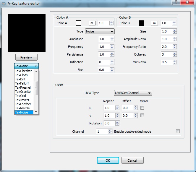
Next, in the pop-up dialog box "V-Ray Texture Editor" that follows selecting the letter "m", select the TexNoise option:
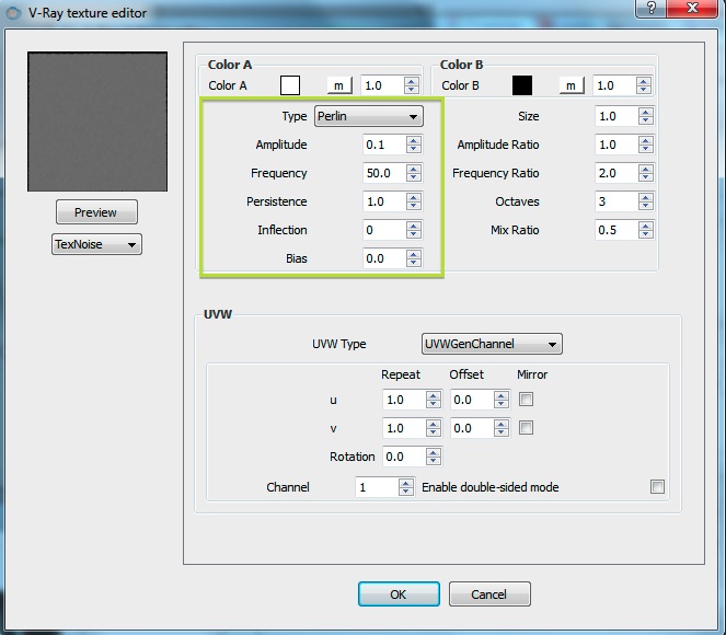
Change the type to "Perlin", the Amplitude to 0.1, and the frequency to 50.
6. To add a bump map on the ground, go to the V-Ray Material Editor", create a material "mySand', go to the Maps tab, and select the letter "m" adjacent to the word "Bump".
Next, in the pop-up dialog box "V-Ray Texture Editor" that follows selecting the letter "m", select the image file "sand.jpg" for the bump map.
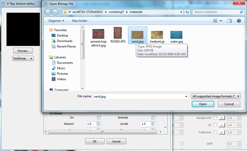
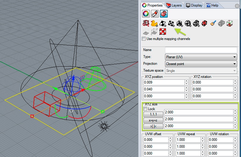
Select the ground plane, and go to the properties attribute and then the texture mapping tool, and select "Planar Mapping" icon and trace the corners of to the ground plane highlighed below. Next use the XYZ size of 2, 2, 2 to scale the bump map at 2.0 units in the direction of each axis.
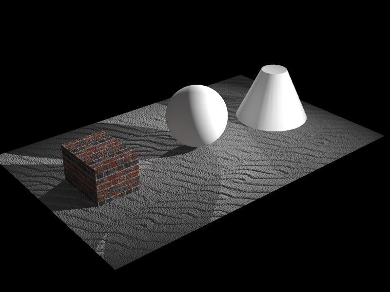
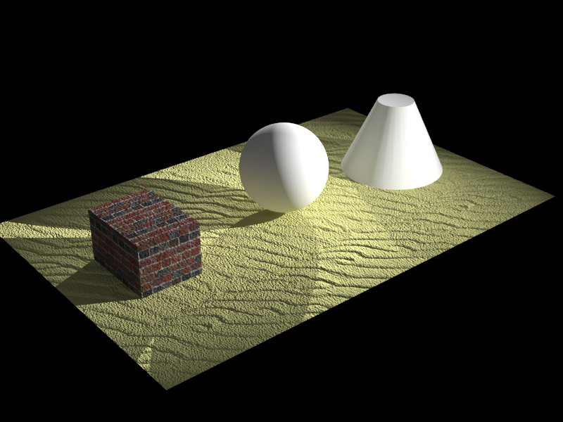
Re-render the geometry in V-Ray amd note the bump map representation on the ground with a neutral gray color.
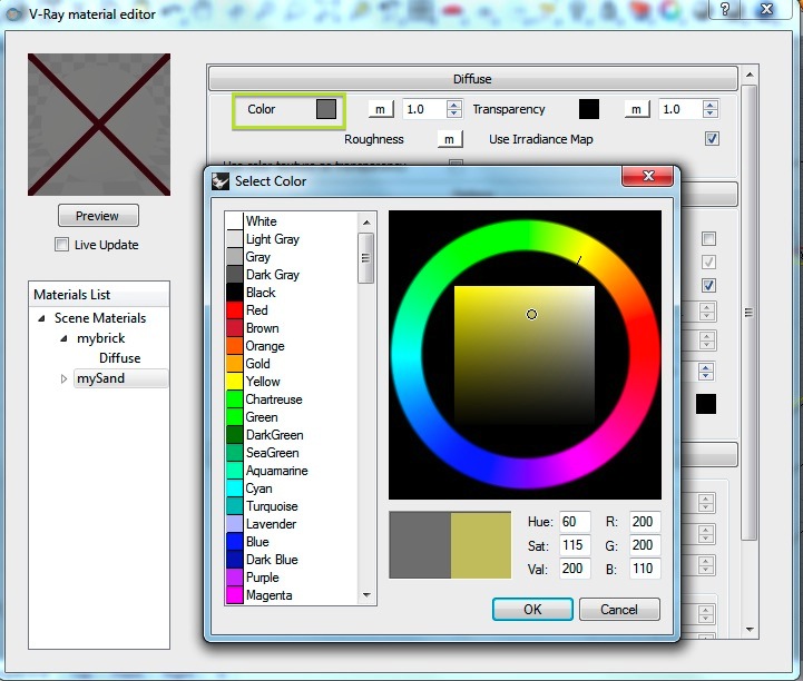
To establish an alternative sand color, return to the material editor and the diffuse tab for "mySand", select the color rectangle and then use the "Select Color" dialog box to determine a new color.
Re-render the image.
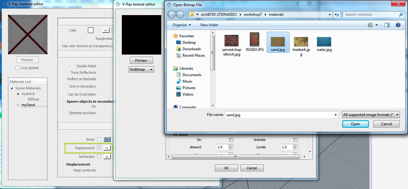
7. Alternatively, select off the "Bump" map option for the sand, select the check-box for Displacement within the same tab, and once again select the file "sand.jpg"
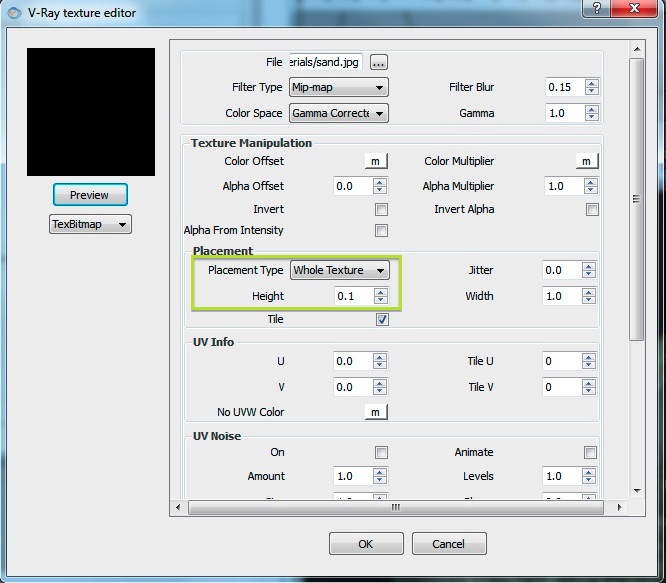
TheV-Ray texture editor follows selection of the "sand.jpg" file. Within the editor, change the value of Height to 0.1 and then render.
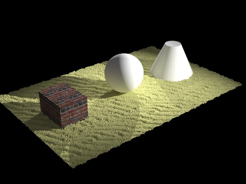
Note the appearance of the sand with a more self-evident 3D appearance casing more realistic shadows and occluding the base of the brick cube and the cone. However, the rendering time also increases when switching from a bump map to a displacement map. The tradeoff between realism and rendering time needs to weigh in any decision to use the displacement map method.
7. Reflection map
Copy the folder "reflectionMapImages" from
the classes folder to the same folder where you had placed the
"materials" folder.
Create a material named "myGlass" with an IOR of 1.55 as was
done in workshop 6, apply it to the sphere , and render it.
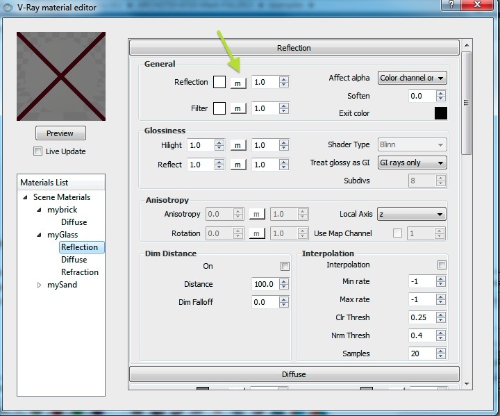
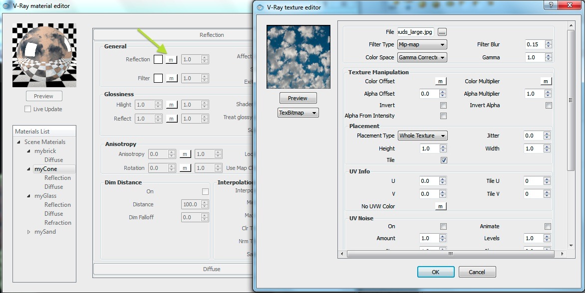
In the V-Ray material editor, select the Reflection tab for "myGlass" and select the letter "m" adjacent to the word "Reflection":
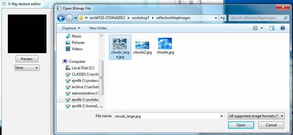
Select the image "cloulds-large.jpg" from the folder "reflectionMapImages"
Render the result.
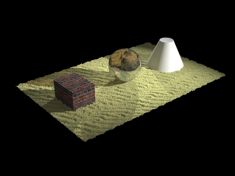
For the Cone, create material called "myCone" in with a reflection layer. Change the diffuse color to light-grey and add the same reflection map.
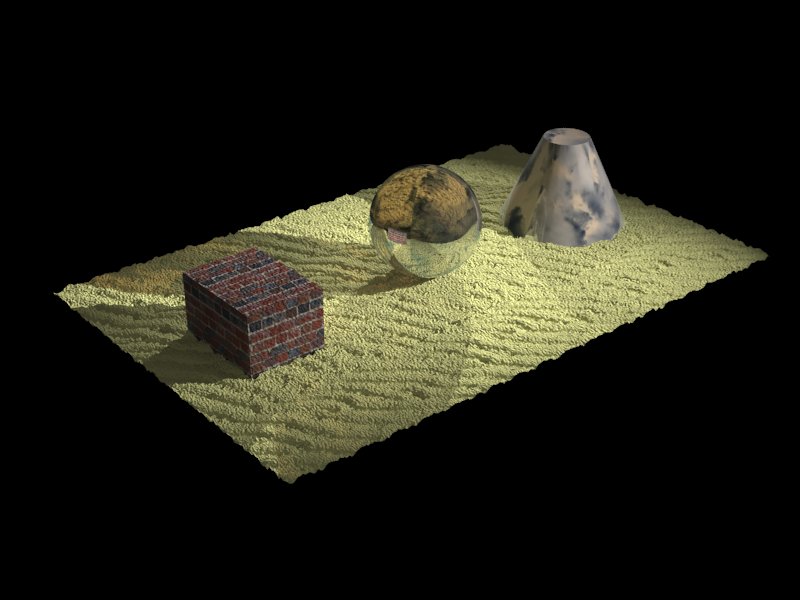
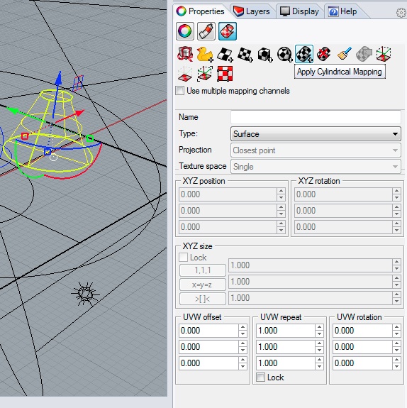
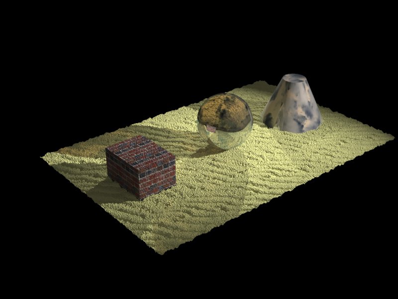
Next, try a cylindrical texture map for the cone and re-render, and see the difference in the results.
8. Transparency Maps
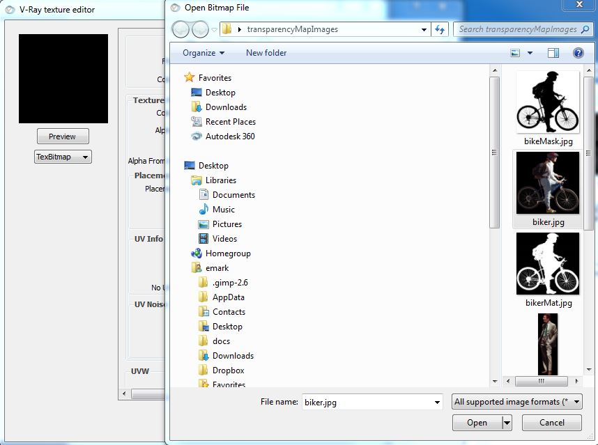
Download the folder "transparencyMapImages" from the examples folder on the classes server.
The original images were obtained as free samples from a web site (the actually web address has been lost). Each of these images has been modified within Photoshop to be used in two pairs.


Each pair includes a photographed figure on black pixel background and a transparency mask of the same figure in black pixels on a white pixel background. In Photoshop, the pair of images was created in thee steps:
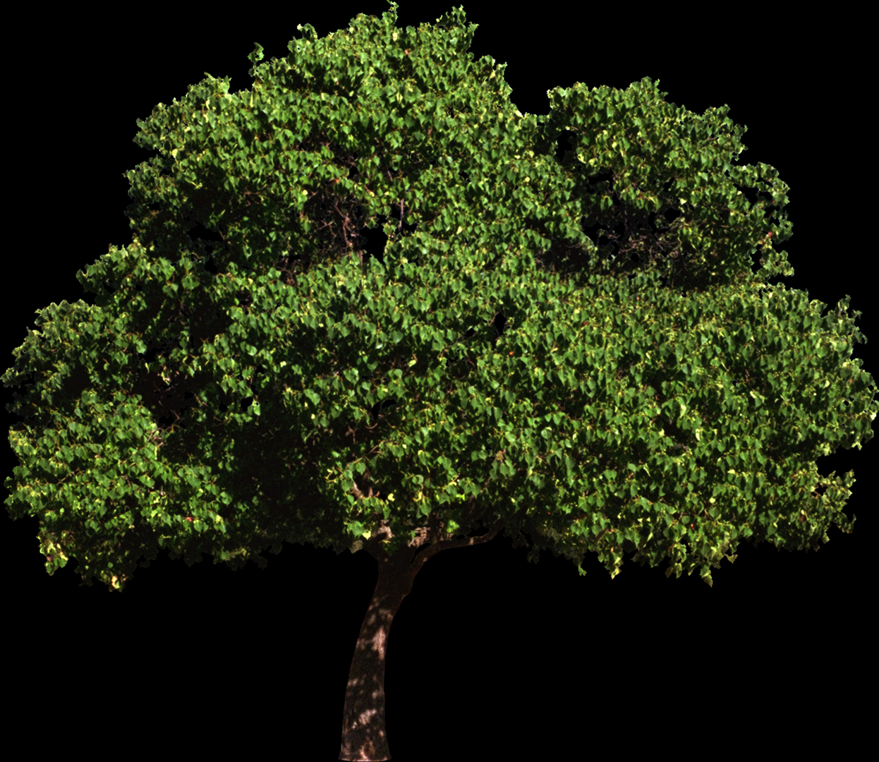
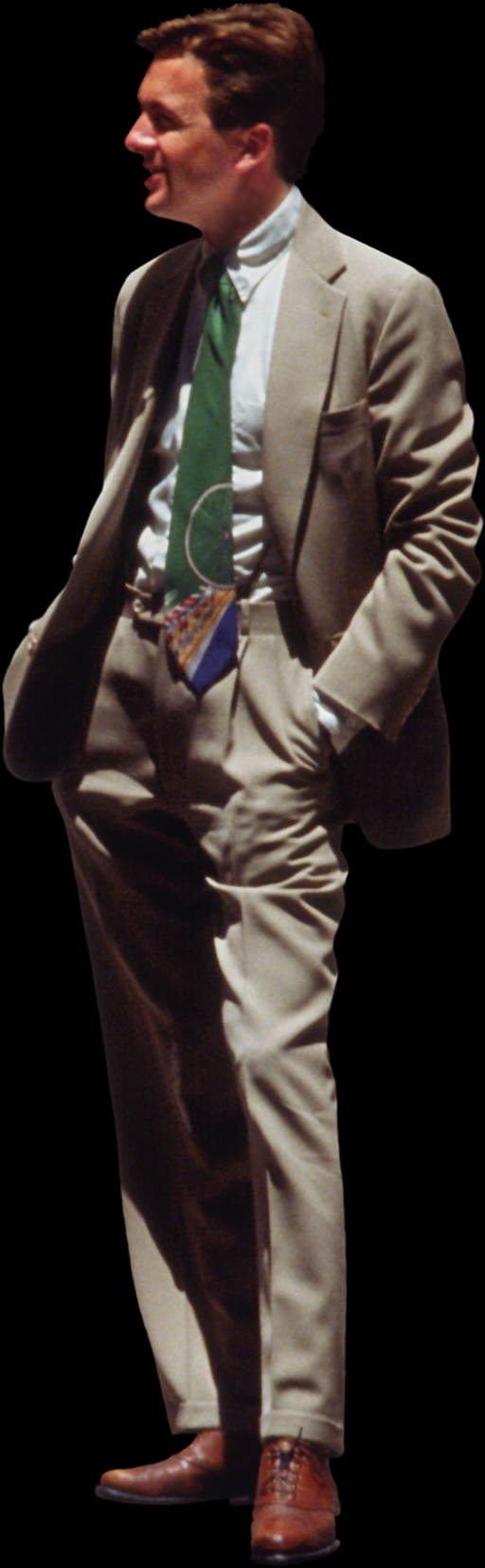
1. start with the original figure:
2. use the magic wand tool in Photoshop to select the pixels of the background, invert the selection to select the pixels of the figure, and then use the Photoshop fill tool to covert the the pixels to white:

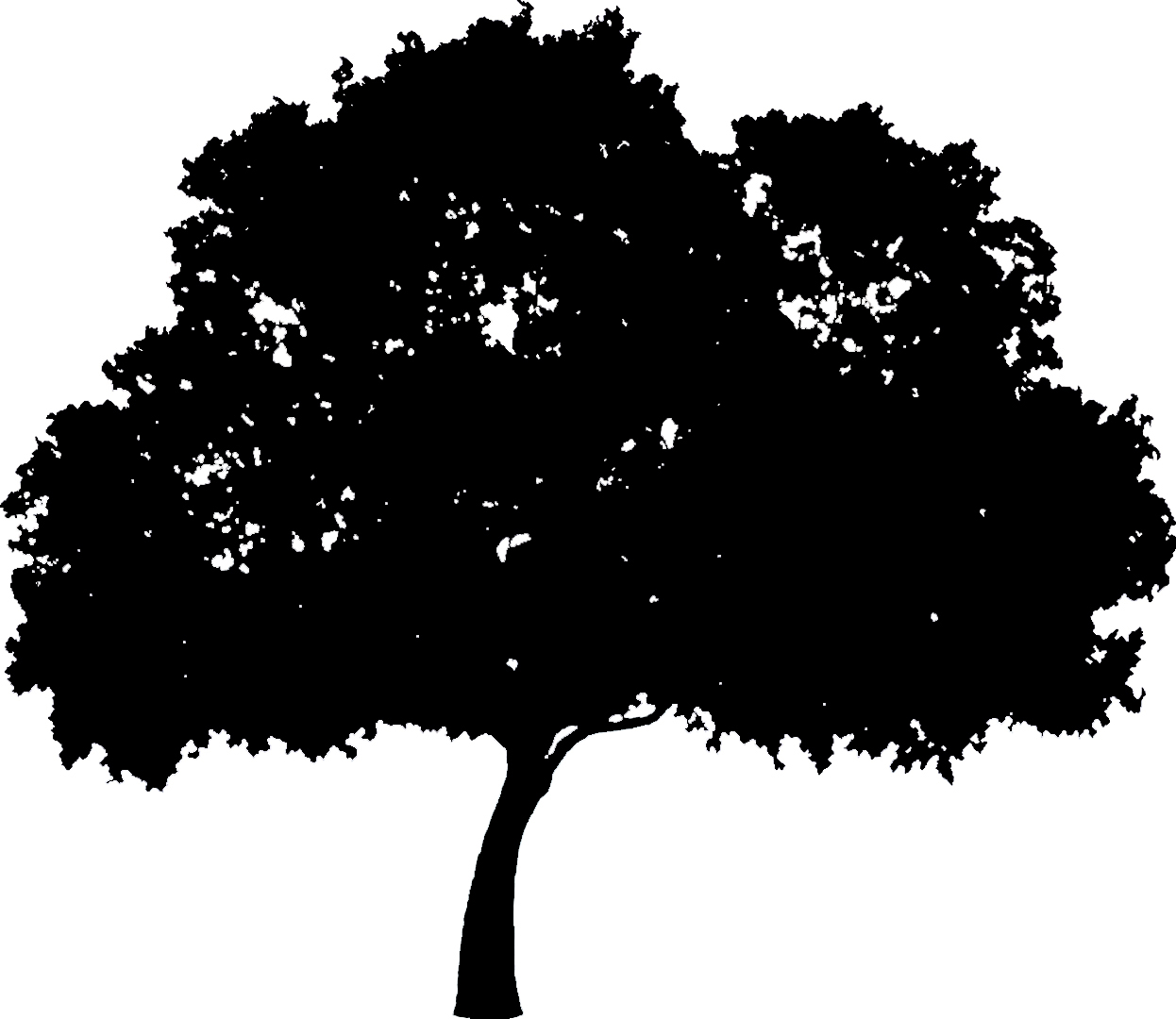
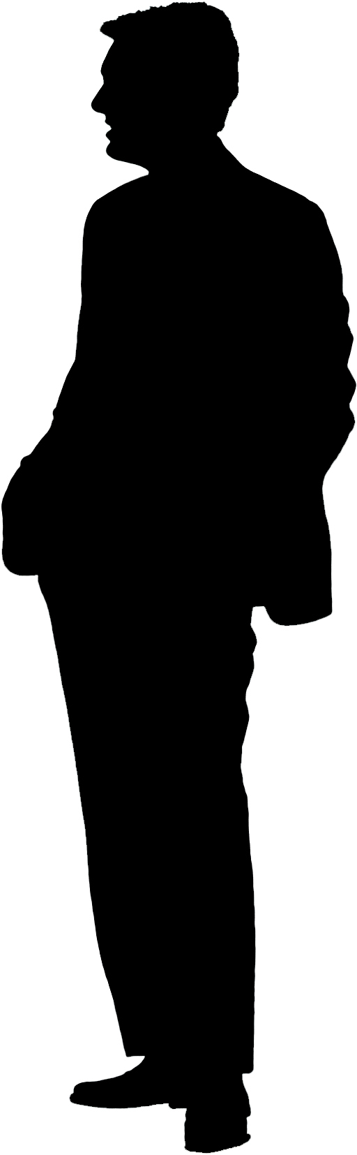
3. Use the invert tool in Photoshop to get the
black pixels figure on a white background:
Step 3.
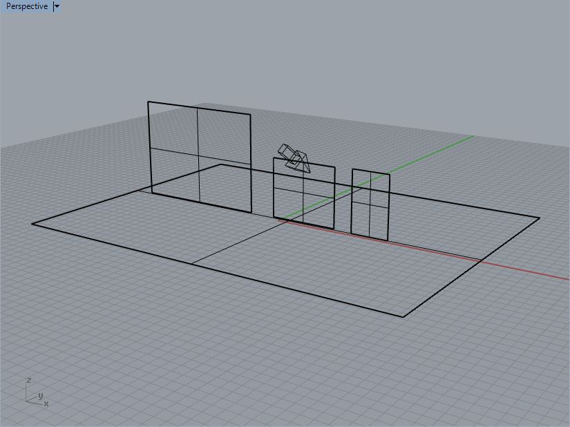
Create a new Rhino file with three vertical surfaces on a horizontal surface that are roughly proportional to the tree, bicyclist and pedestrian. Add a V Ray sunlight.
Within the V-Ray material editor, create three materials named 'tree", "bicyclist" , and "pedestrian"
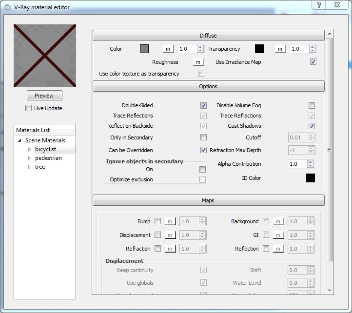
For the "bicyclist" material, go to the diffuse tab and select the letter "m" adjacent to the word "color", and within the "V-Ray" texture editor, select the option TexBitMap, and then select the file "biker.jpg" from the transparencyMapImages folder.
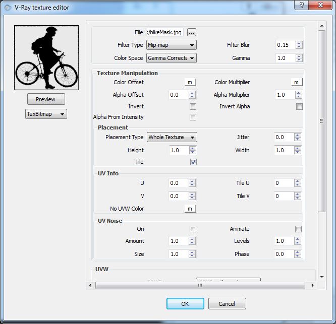
Similarly, go to the diffuse tab and select the letter "m" adjacent to the word "transparency", and within the "V-Ray" texture editor, select the option TexBitMap, and then select the file "bikerMaskt.jpg" from the transparencyMapImages folder.
Do the same for the pedestrian and tree materials and render.
![]()
Part II: Maxwell in Rhino Continued
This supplmentary set of notes on Maxwell is optional reading and extracurricular. The Rhino plugin for Maxwell addresses scale according to two different settings. Map projection is in part handled via Rhino's separate texture mapping control. Combining Maxwell and Rhino tools, texture mapping can be developed with great flexibilty to match specific object conditions.
For a more complete treatment of these techniques in Maxwell see See Maxwell For Rhino Plugin Manual
Within workshop Notes 6, the technique of making a basic texture map was illustrated in Rhino. Within workshop Notes 10, those techniques were expanded for Luxology. Similarly, here, the techniques for texture mapping are expanded for Maxell.
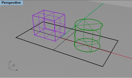
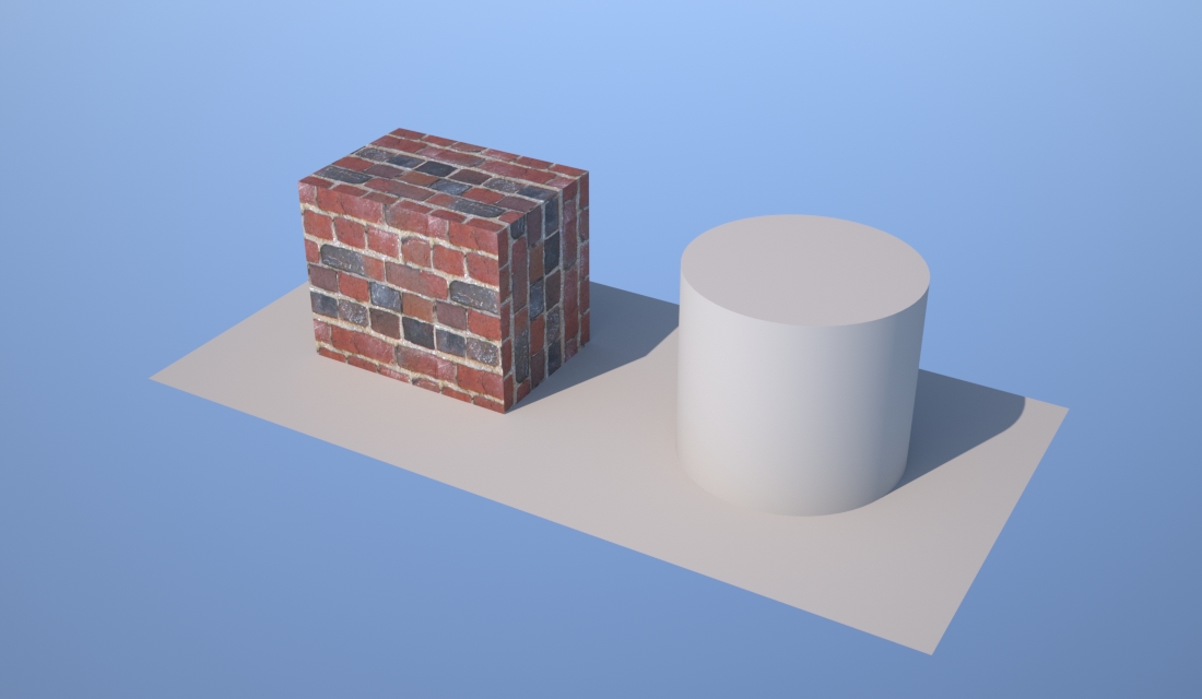
Begin by making a solid box and a cylinder, and place these objects on a simple planar surface.
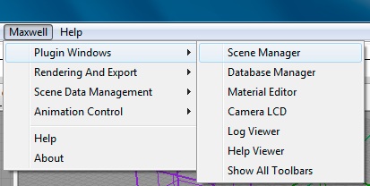
Go to the Maxwell Menu and Open the Maxwell Scene Manager:
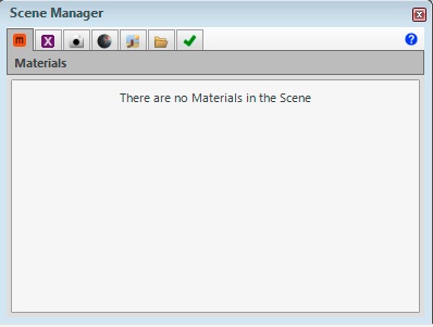
Next, go the Materials tab
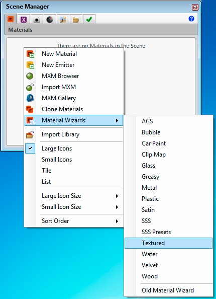
Right-click in the white area of the dialog box, select the "Material Wizards" option to create a new material, and select the "Textured Option".
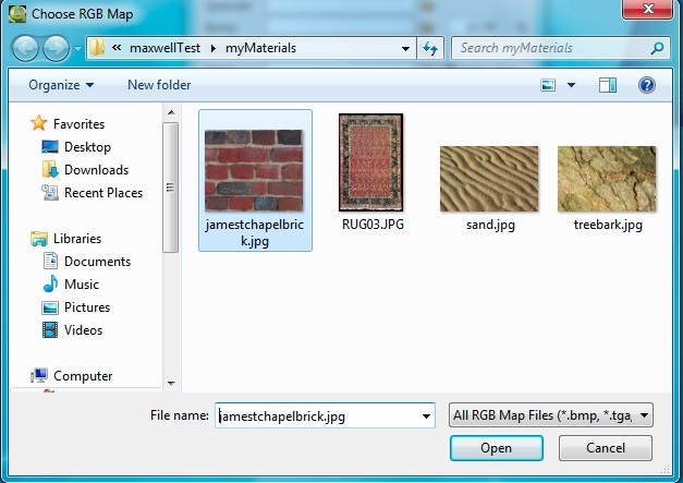
Within the "Textured Wizard" dialog box, choose the yellow folder icon adjacent to "Color" and select an image file:
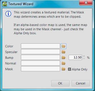
Load in a texture map based upon a jpg image file.
Similarly, choose the brick photo for the bump map such that both the "Color" and "Bump" map areas now include links to the jpg texture.
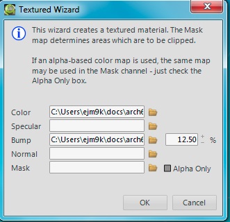
Next, select the OK button, and the material appears in the Scene Manager Library.
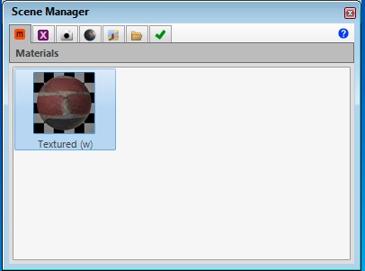
Now double-click on the brick to get to the "Material Editor". Select "BSDF" under the the title "Base".
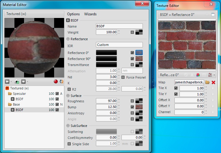
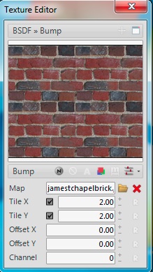
Note that there are two alternative settings for controlling how the texture map is applied to any given object in Rhino. The default setup is to determine the number of tiles that fit to any surface. In the window above. the number of tiles is given at "Tile X" = 1 and "Tile Y" = 1, thus creating single tile on each surface to which it has been applied. If we change these numbers to 2 and 2, then essentialy there would be four such images applied to each surface. For consistency, this should be done for the map adjacent to "Reflectance 0", for the map adjacent to "Reflectance 90", and for the map adjacent to "Bump"through the Texture Editor.
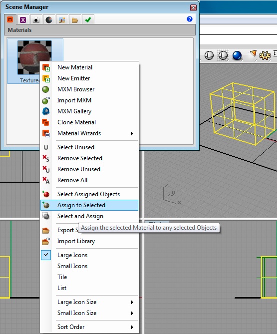
Having completed this adjustments, right-click on the brick material in the "Scene Manager" dialog box, and use the "Assign ti Selected" operator to assign the brick to the cube inside Rhino.
If now rendered in Maxwell, the cube appears as follows:

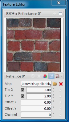
Or, the option exists to change to the second scheme, one based upon real scale rather than a specified number of tiles per surface. To do this, select the symbol "m" on the right-hand side of the dialog box and just below the image for the material. Note that now the Tile X and Tile Y numerical value system now refers to 2 x 2 meters, the measurment unit upon which this is based. For consistency, this also needs to be done for the map settings for Reflectance 90 and Bump. The sample size changes accordingly.
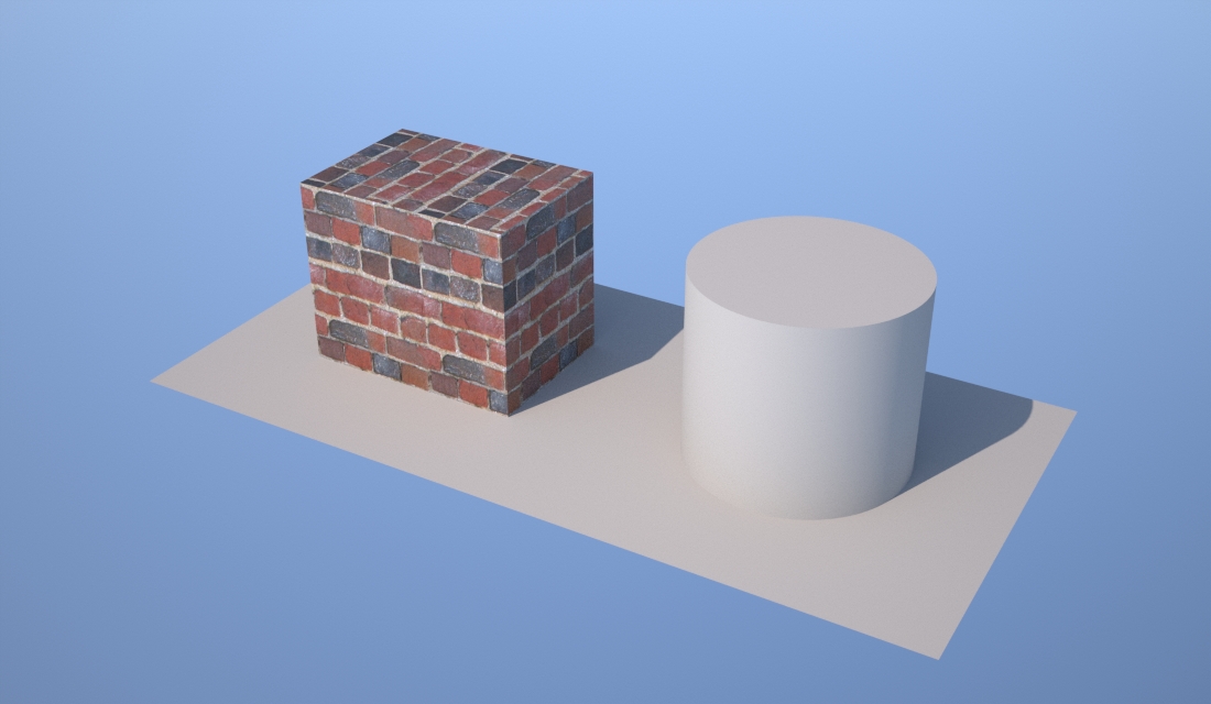
Moreover, the resulting rendering also changes the relative scale of the brick.
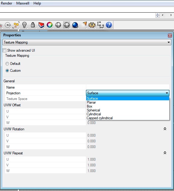
Moreover, note that our default texture mapping method isn't well suited to the block. Brick on the side are in vertical rather than horizontial courses. To correct this in Rhino, we go to the object properties of the block, select "Texture" and the radio button labelled "custom", and adjust the texture mapping option to surface.
The resulting rendering is as follows:
Make a new material with the same brick texture map. Apply the cylinder mapping technique to the cylinder, disable real scale, set the tiling in x and y to 4.0 x 1.5 for each of reflectance 90, reflectance 0, and bump, similar to what was done above, and get the following result.
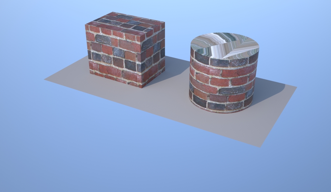
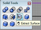
Note that the top of the cylinder isn't being mapped appropriately. Here, depending upon the details of the construction of the cylinder, a number of options may be feasible. One strategy is to separate out the top of the cylinder from the rest of it, and to apply a separate texture map to it. Within the solid modeling palette of Rhino, select the Extract Surface tool, select the top surface of the cylinder and hit the enter key.
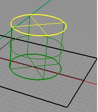
Create a new planar texture map to be applied to the extracted cylinder top, turn on real scale, adjust the size parameters to 2 x 2 in x and y for each of reflectance 90, reflectance 0, and bump, for the cube, cylinder and the cylinder top, then the result is as follows:
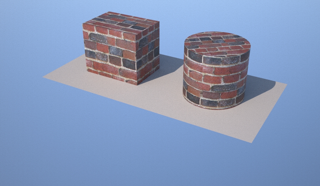
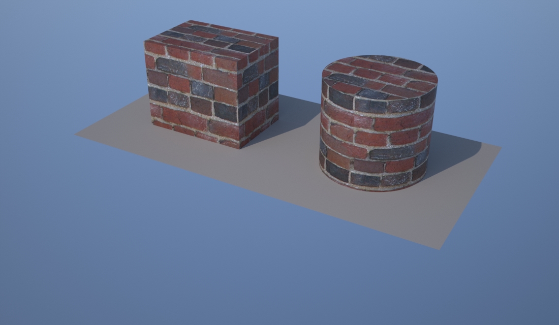
However, the result was less than satisfying since the scale of the bricks is too small. We need to adjust the map to an appropriate scale. Disabling the "real scale" option within the material editor for the top of the cylinder initiates this process. Next, select the surface of the cylinder top again, and under the properties tool, select "Texture Mapping". Finally, change the projection type to "Box" and select the "Equalize Button". Render the model again and you will likely obtain the following result:
In terms of real world application, the tops of both of the objects above would need to be treated with greater nuance. Bricks would not be set within the top of either the cube or cylinder in the way just described. More adjustments to scale and texture offset values (offset is available in both Rhino's texture mapping tool as well as through Maxwell.).
Within Rhino, use the Object Properties/Plugin tab to also control the scale of the material relative to the object, with values for "x", "y", and "z" establishing the scale separately along each axis in 3D space.