COMPUTER
AIDED
ARCHITECTURAL DESIGN
Workshop 12
Notes,
Week of November 10, 2014
LIGHTING AND MATERIALS
Part II and III of this workshop is developed after techniques described in Maya 8 for WIndows & Macintosh (Visual QuickStart Guide) by Morgan Robinson, and Nathaniel Stein, Peachpit Press, 2007 ± § - see on-line version of this textbook. it contains examples that are reinforced by background concepts in Chapters Chapter 14 + Chapter 15 (part), pages 349 402, which can be read online when on ground or connected through UVA Anywhere.
The Robinson text is an especially well written introductory text in comparison perhaps with some more recent tutorial books. For additional online resources for later releases of Maya, see the references at the end of the syllabus for Arch 5420: Digital Animation and Storytelling.
PART I: LIGHTING
Lighting types commonly used are 1) Ambient, 2) Distant/Directional, 3) Point and 4) Spot Light which appear from left to right in the Rendering Shelf tab in Maya. Ambient light provides general background illumination. A Distant/Directional light provides parallel light rays from a specific angular orientation, and may be used to mimic such distant lights as sunlight or moonlight. A point light is an omni-directional light that sends light out in all directions from a single location. A directional light sends light in a specific direction at a specific angle from a source location to a target location.
Key and Fill Lighting: A typical three point lighting setup has a Spot light (also known as a Key light) to the upper right of model at full intensity to provide high contrast shadows, a Point light (also known as a fill light) to the upper left of the model at lower intensity filling in middle gray values, and a back spot light (also known as a back key light) at lower intensity than the front spot light and that provides some three-dimensional depth to the rendering.
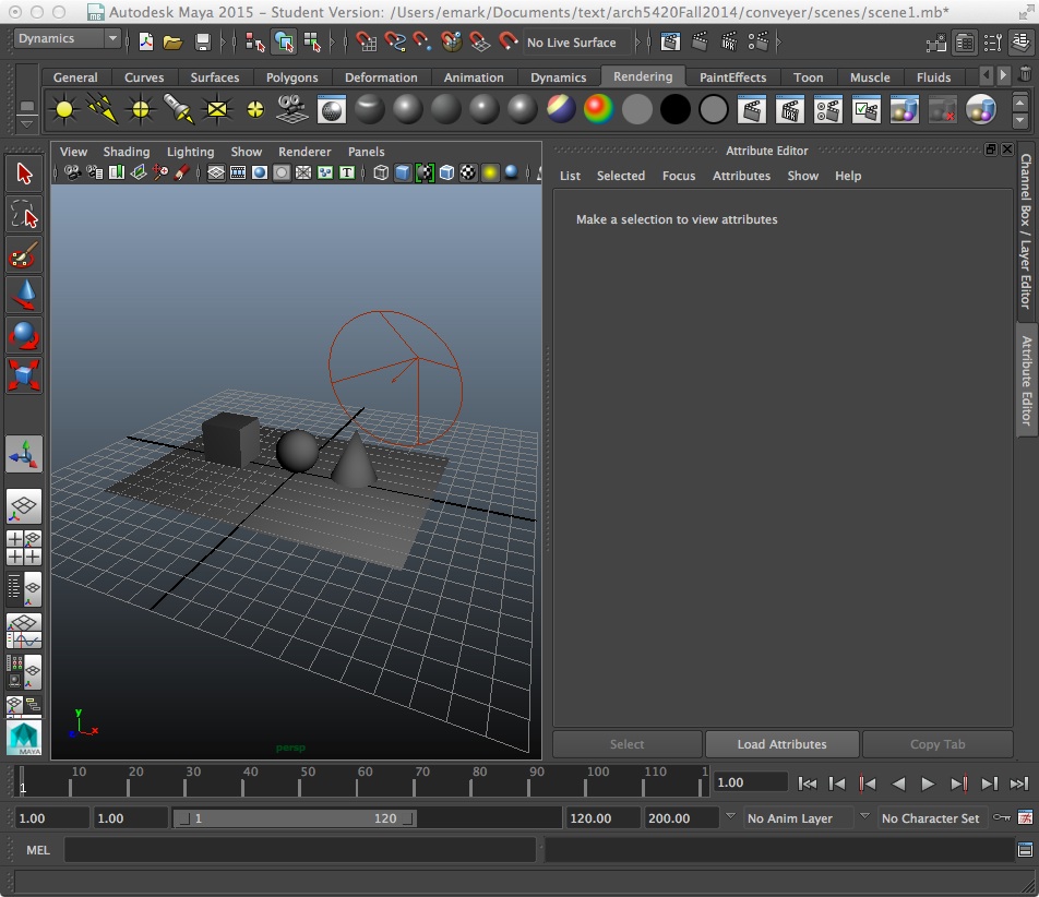
Open Maya, go the Polygon shelf tool, and create a simple box, sphere and cone and place them on top of a polygon plane similar to what we've explored in Rhino previously.
Add spot light.

With the spotlight selected, to the top of the screen menu item "Modify/Transformation Tools/Show Manipulator Tool" to get control of both the source of the spotlight and the target. Move the source of the spot light above and to the right of the polygons, and move the target of the spot light to an area just below the sphere. With the spot light selected, open the attributes editor (third icon from upper right-hand corner of Maya window) and resize the light's "cone angle" until it encompasses all the polygons within the view. Within the attributes editor for the spot-light, turn on ray-trace shadows for the spot light.
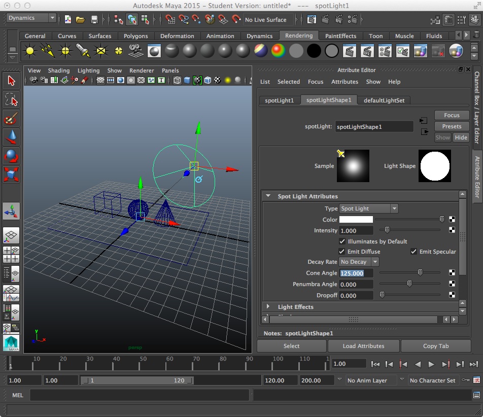
Go into lighting mode by hitting #7 key
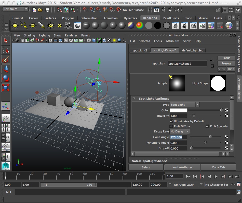
2. Now add a point source light to the upper-left area and a spot light to the upper right area of the model space for fill (point light)) and back light (spot light). Optionally turn off the shadows for these two lights. The shadows for the earlier spot light is probably sufficient to lend clarity to the rendering. Use the show manipulator tool again to reposition the new lights (target and source).

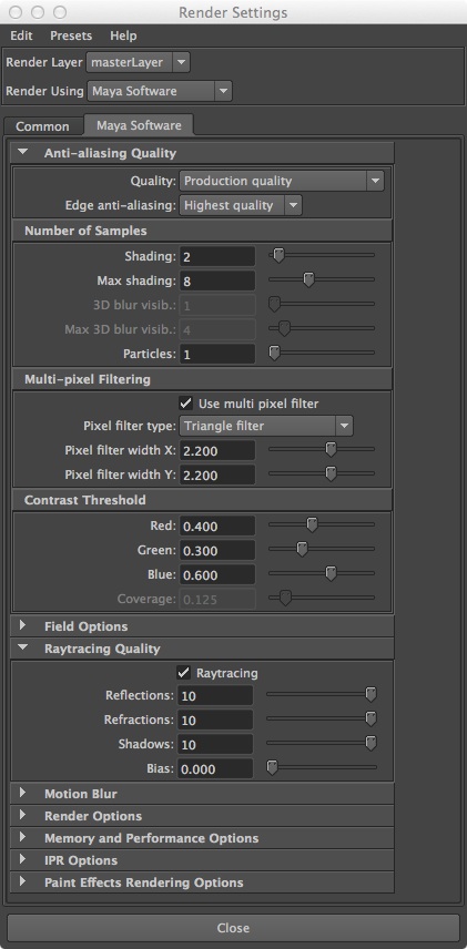
3. Next, return to the "Rendering" shelf tool, and open the render settings dialog box (highlighted in green below).

Under the Maya Software tab, and in the quality tab, select the preset "Production Quality" and then go to the "Raytracing" tab and select to on the check-box.
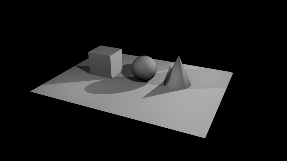
4. Rendering the image produces the following kind of result with all lights casting shadows.
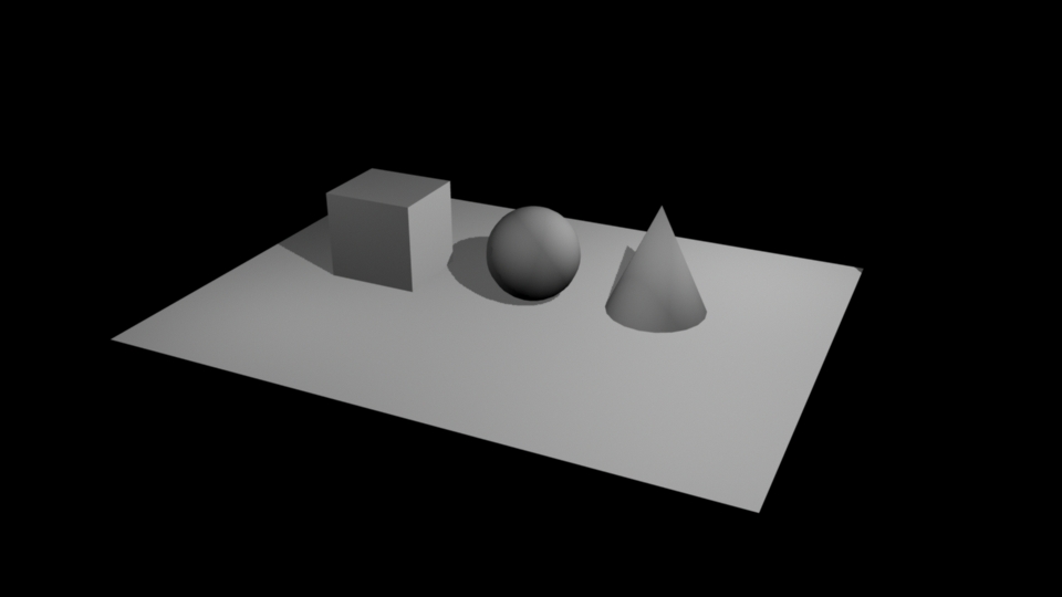
Rendering the image produces the following kind of result with only the first spot light (also sometimes called the key light), casting shadows.
PART II: MATERIALS
1.
Shaders in Maya are based upon standard rendering algorithms and
include the following types:
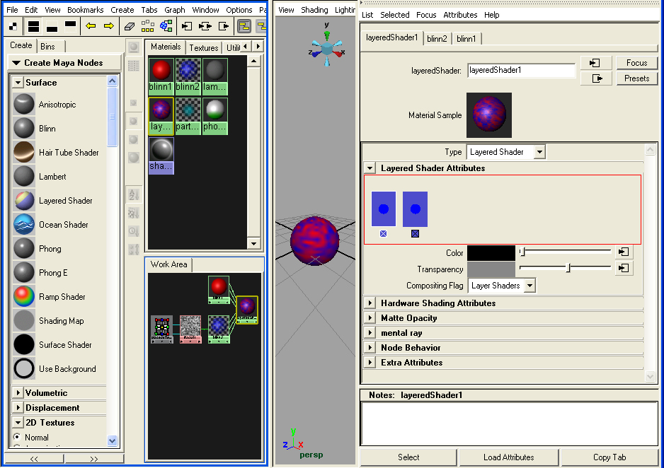
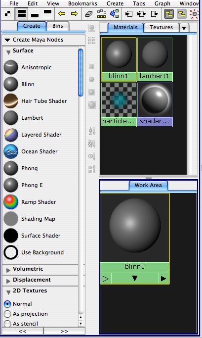
These types of shaders are acessible through the hypershade dialog box or Window/Rendering Editors/Hypershade
2. Materials Some Definition of Textures and Methods
Materials
reference attribute nodes that
determine look of an object. This includes
Texture
– an
material that is mapped to object
Types: procedural (based on
an algorithm) and
image (based on a
photograph).
Bump Map – image read for its gray scale value that makes a material have the appearance of a surface relief
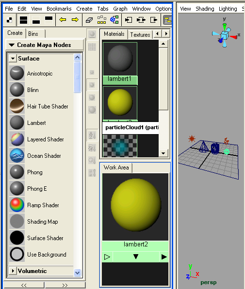
3. Menu items in Hypershade window (Left to Right)
![]()
Toggle
bar – hide or show
Create bar leaving more or less work area
Show top and bottom tabs - shows materials/textures as well as work
area.
Show bottom tab - shows work area
Show top tab - shows materials/textures
Show previous graph (in work area)
Show next graph (in work area)
Clear Graph bar – clears out any nodes in work area
Rearrange graph bar – cleans up work area
Graph materials on select objects – finds material assigned
to object
Show input connections
Show input and output connections
Show output connections
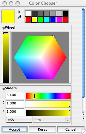
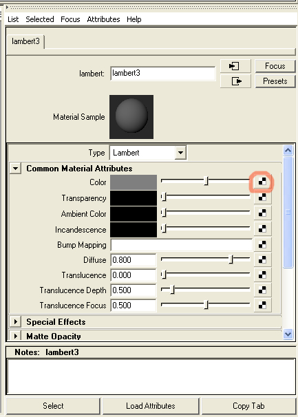
4. Basic material properties:
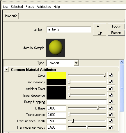
Color
– RGB or HSV selection
model color
Transparency – degree to which material is transparent
Ambient Color – brightness or darkness of whole material
Incandescence – create appearance of giving light
Bump mapping – makes a surface appear bumpy
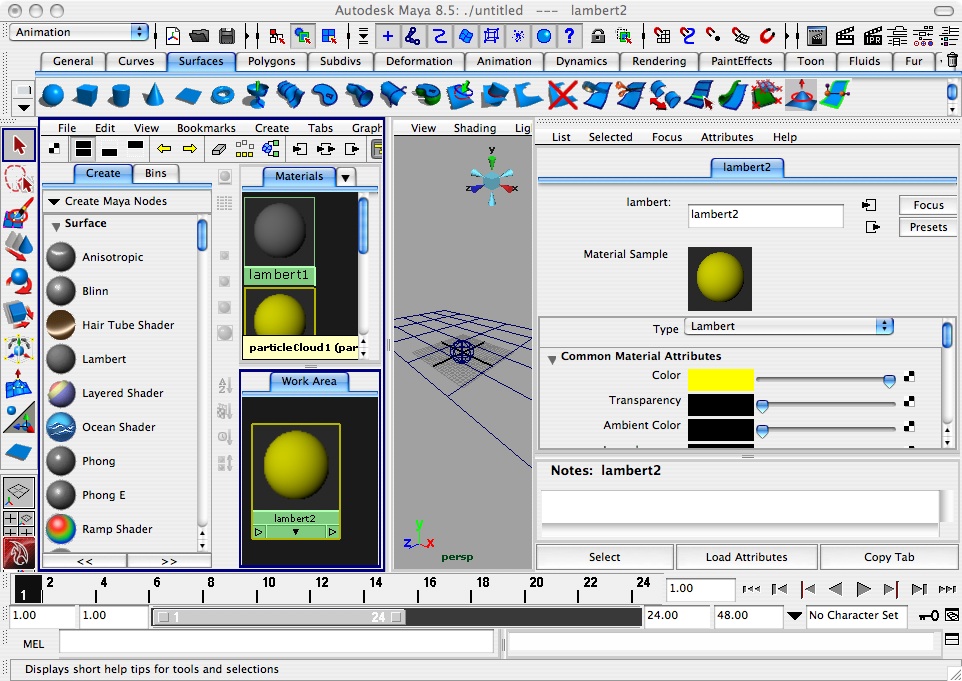
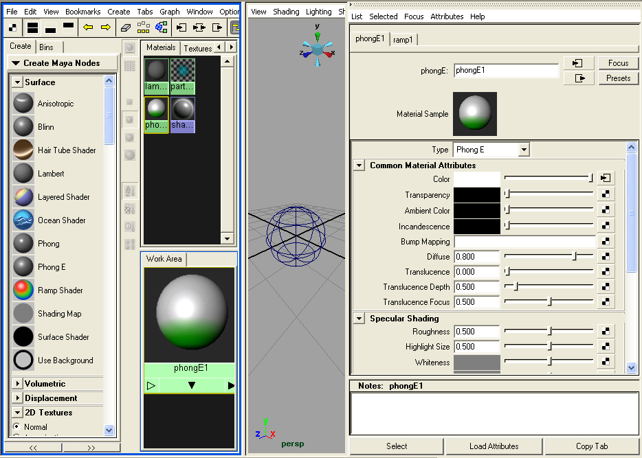
5. Example of use of simple material definition and assignment
Go to materials editor by invoking the menu sequence select Windows >Rendering Editors > Hypershade.
6. Texture mapping nurbs surface
Prepare or obtain an image file of some material such as brick.jpg file. Make a lamber shader. In the color selection area on the right-hand side of the the screen, select the checkered symbol and follow the dialog box to load the brick.jpg file.
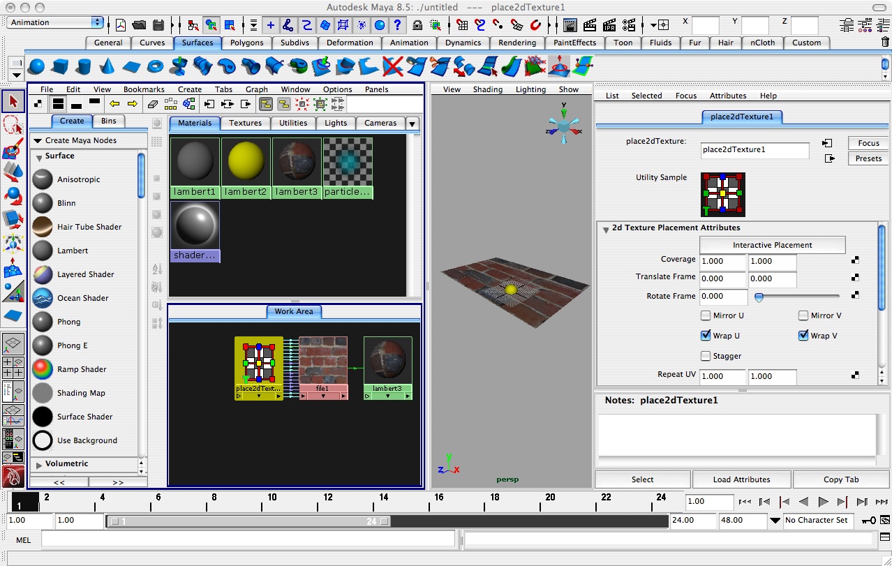
Adjust the 2d Texture Placement Attributes. Note:
7. Projection Map
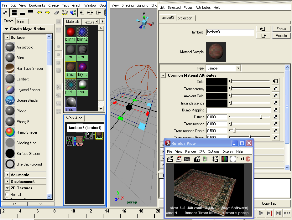
[If surface appears to be moving through texture, then in Rendering mode, select the surface, and then from the Texturing menu select “Create Texture Reference Object”]
8. To Improve Quality of Rendering
9. 3D Paint Tool
PART III: ADDITIONAL MATERIAL AND MAPPING TECHNIQUES
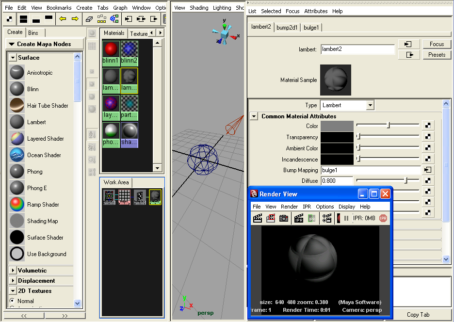
10. Bump Map
11. Ramp texture (eyeball)
12. Layered Shader