COMPUTER AIDED ARCHITECTURAL DESIGN
Workshop 3 notes, week of September 15, 2014 (preview during week of September 8).
Navigation in 3D and Simple Solids
1. Navigating in 3D and directional control
The Status Bar is anchored in the lower part of the application window and echos back the global coordinate information:
![]()
Using Modeling Aids in Rhino:
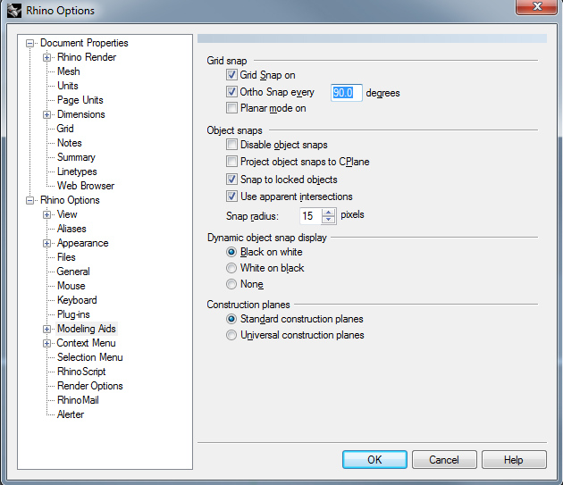
1) Snap (to grid), Ortho, Planar, OSnap (to object) are all located on the Status Bar at the bottom of the screen. Individual settings can be reached by right clicking on any of these words and selecting Settings. Or, you can select Tools / Rhino Options. Click on the Modeling Aids page to see specific options for these tools. Under Grid snap, you can control the ortho angle. Here you can also select the option for "project object snaps to CPlane."
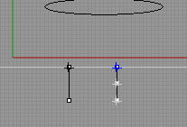
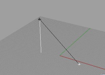
2) Smart Track: This is a system of temporary reference lines and points using implicit relationships amongst elements and coordinate directions.
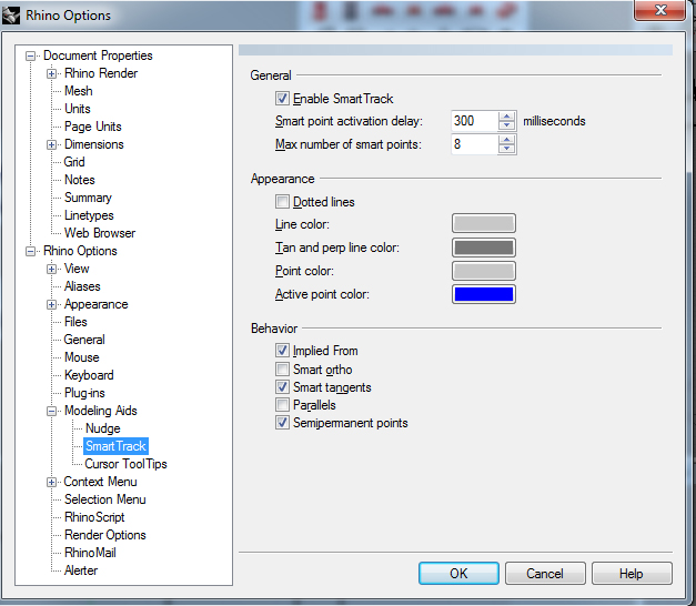
Expand Modeling Aids by clicking on the little box with the + in it. Click on Smart Track. Here you can toggle Smart Track on and off, edit the appearance of these guiding hairs, and specify the behavior.
These reference elements are only temporary for the duration of the command. You can snap to these tracking lines and smart points intersections as well as the element itself.
There are two ways to capture smart points: automatically and manually. Tracking lines are shown when points are captured and is predicted accordingly.
Automatically: Hover over the object snap point
Manual: Use CTRL to place a manual point. CTRL 2x to clear all points.
NOTE: To ensure that you are drawing at right angles, it may be helpful to toggle on/off the Ortho command (F8) as you are using Smart Track, or make sure you select the option Smart Ortho under Behavior in the Smart Track options dialogue. This will allow you to orthogonally track the previous point without going back to capture that point.
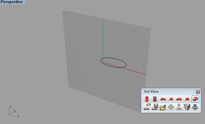
2. Introduction to Construction Planes and Saved Views
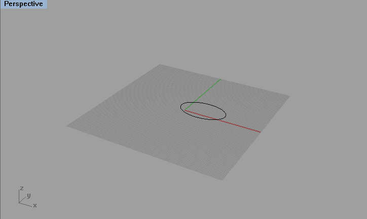
Construction Planes vs. grid: The grid is a visual reference to the construction plane, which is infinite. The grid's size and spacing dimensions can be controlled under File / Properties and under the "grid" page. The x and y axes are shown in red and green (respectively) by default. This will be explored further in future workshops.
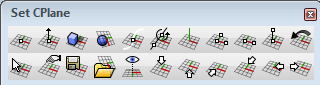
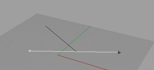
Find the CPlane icon along the standard toolbar (towards the top of the screen). Click and drag on the first icon to pull out the tool subset. From here, you can define/modify a construction plane by selecting an origin (1st icon), through 3 points, align it to an object/surface, or elevate any plane (2nd plane), etc.

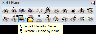
You can also used Named CPlanes to save any construction plane. Simply select the icon as shown below to bring up the dialogue box to name and save a plane.
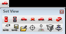
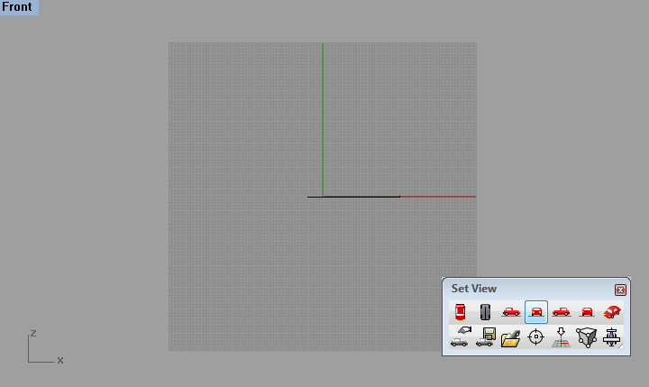
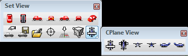
Find the car icon to tear out the SetView floating window. This is for looking at the world construction plane from different views (top, right, bottom, etc.).
One thing to note: When you change a view (to front for example) and then revert back to the perspective view, the construction plane aligns itself to that previous view (front).
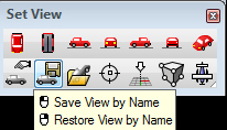
Saving Views: If you select the icon shown below, you can save any view by name.
This is different than the icon with a plane. This toolset is for looking at the construction plane from different views (top, right, bottom, etc.).
3. Polar vs. XYZ coordinates
1) Angle Units: Degrees vs. Radians
Degrees are assumed unless otherwise specified. NOTE: Positive angular measurement is counterclockwise.
Degrees: d, deg, degs, degrees, (degree symbol)
Radians: r, rad, rads, radian, radians
Other units are possible for use such as Degrees/Minutes/Seconds and Surveyor's units.
2) XYZ coordinates
- Type in x, y, z coordinates into the command prompt to place points. If you omit the z, then it is assumed that the point will lie on the active construction plane. If you type w in front of the x, y, z, then the world coordinates are used.
- Other ways of notating points:
Polar (radius<rotation angle) - 17<45
Polar (radius<rotation angle,z) -17<45,8
Spherical (radius<rotation angle<z-elevation angle) - 5<30<45
Spherical (x,y<elevation angle) - 5,6<15
Surveyor (distance<N/SangleE/W) - 11<N30d22'54.43"W
4. Inputting Dimensions, Angle, and Distance Constraints:
Dimensions can be explicitly defined by typing in distances in the command prompt. You can mix fractional and decimal input. Feet and inches can be written as 1", 1in, 1inch(es), 1'2-1/2("), 1', 1ft, etc... NOTE: Do not enter any spaces. If you need a calculator, you can type in "calc" in the command prompt.
Distance constraint for a line: click a location for the first point, type in the explicit distance in the command prompt, and the line will be restricted to that distance around the first point. Click again to confirm the second point, or specify an angle.
Angle constraint for a line: click a location for the first point, type in "<45" to restrict line 45 degrees from the last point. Click again to confirm the second point, or specify a distance.
5. Other methods for directional control:
Directional locks: Use the TAB key to lock the cursor's direction of travel. This is good for drawing a line to pass through a specific point and you want it to extend beyond it. For example, to constrain the direction of a line, click on a location for the first point, move the cursor to anywhere you want to constrain the relative direction to, hit TAB, and then the line will be constrained to that direction.
Typically the first base location of a tool can be located anywhere in the model space. The second point is constrained to a plane crossing through that point and is parallel to the construction plane. The Elevator Mode is another useful way of manipulating that second point.
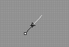
To define a point that is a given distance above/below a construction plane: Start a curve/polyline and place the first point. For the next prompt, hold the CTRL key and click and drag (without letting go of the click) the second point vertically.
6. SOLID PRIMITIVES
There are a range of solid modeling options: shapes, extrusions.
* To bring up the solid tools select the cube icon from the left hand toolbar on your screen.
* These tools allow you to construct a by drawing a box, sphere, ellipsoid, paraboliod, cone, pyramid, cylinder, torus, pipes, etc. through series of vectors to describe that solid. The tools that have a subset palette (i.e. box, circle, paraboliod) has alternate ways to define the element. For example, a box can be defined by corner to corner, corner to corner and height, 3 point and height.* Follow the command prompt for specific inputs needed per tool. You can type in explicit dimensions (such as 5') for these inputs rather than arbitrarily defining the form by eye.
* The last two tools of this palette allows you to extrude 2d objects into a solid.
7. SOLID PRIMITIVES
Boolean constructions based on solids consist primary of the Union, Difference(Subtract) and Intersect operations.
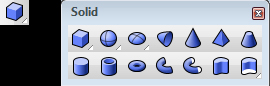
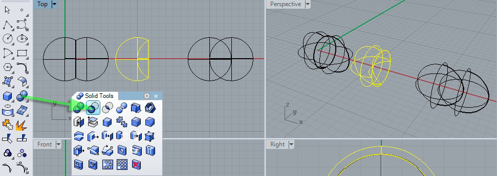
From the "Solid Creation" pallette, create 3 pairs of solid spheres in the ground plane as follows.
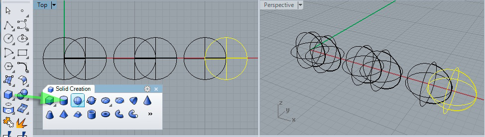
From the "Solid Tools" pallette, select the union operator, select each each solid from the first pair, then use the enter key or right-mouse button, and generate
the union the first pair of spheres.
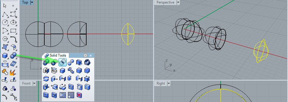
From the "Solid Tools" pallette, select the difference operator, select the left sphere "to subtract from" from the second pair of sphere, use the enter key or right-mouse button, select the right sphere "to subtract with", and use the enter key or right-mouse button again to yield the difference of the first sphere minus the volume of the second sphere.
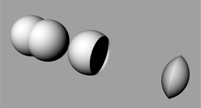
From the "Solid Tools" pallette, select the intersect operator, select each each solid from the last pair on the right, and then use the enter key or right-mouse button, and generate the intersection of this last pair of spheres.
When rendered the three pairs of spheres will now appear as follows:
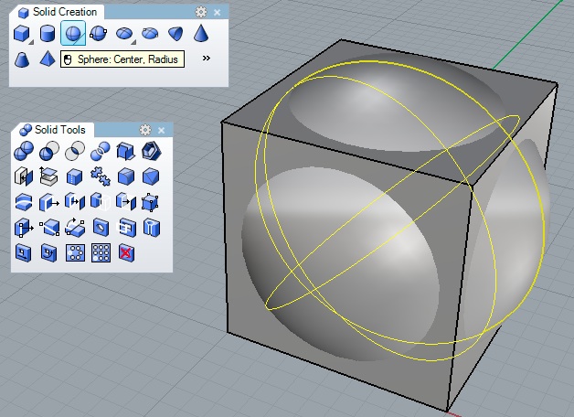
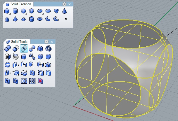
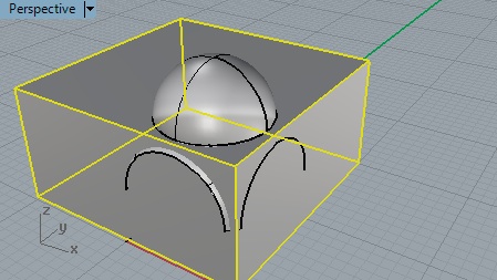
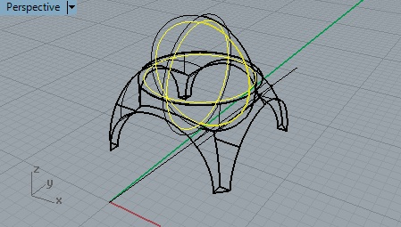
8. CONSTRUCTION OF A PENDENTIVE *
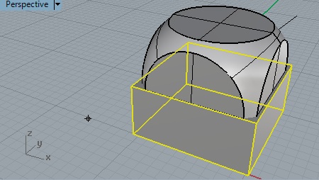
Juxtapose a sphere and cube at the same centerpoint.
Intersect the cube and sphere.
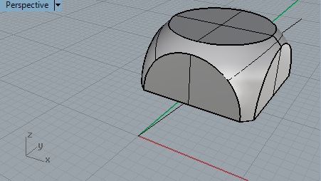
Subtract a cube from the bottom half of the sphere
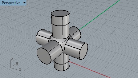
Subtract three cylinders, one oriented for each center x, y and z axis of the previous solid.
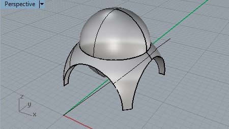
Size and juxtapose a solid sphere to fit the upper hole along the z axis created by the previous step.
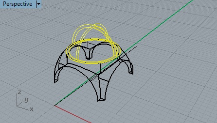
Copy and reduce in scale the previous solid sphere keeping the same center point.
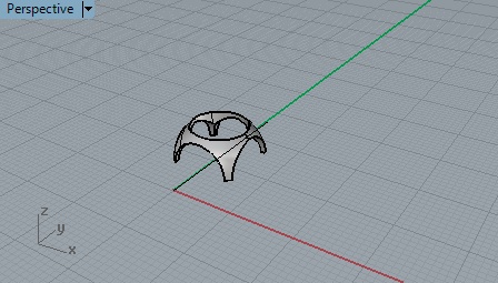
Create a solid cube of sufficient size to subtract the lower half of the the spheres created in the previous two steps.
Subtract the box from the two spheres.
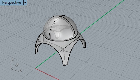
Subtract the remaining half of the inner sphere from the remaining half of the outer sphere to get a hollow dome.
* This exercise was developed as a tutorial by Professor William Mitchell, MIT. Note that we subtracted a box from two spheres in the second to last step, and then subtracted the inner half sphere from the outer half sphere. Given some limits to Rhino's implementation of solid geometry, we could not do this in the reverse order. That is we, could not subtract the whole inner sphere from the whole outer sphere since the surfaces of the two spheres may overlap but they do not touch. However, if we subtract the box from the two whole spheres first, then the remaining half spheres do touch, and this condition allows us to proceed with the final subtraction to form the dome. Within other solid modeilng software we could have subtracted the inner from the outer whole spheres and would have succeeded in creating a hollow sphere. This difference between solid modeling operations is not uncommon between different software implementations.
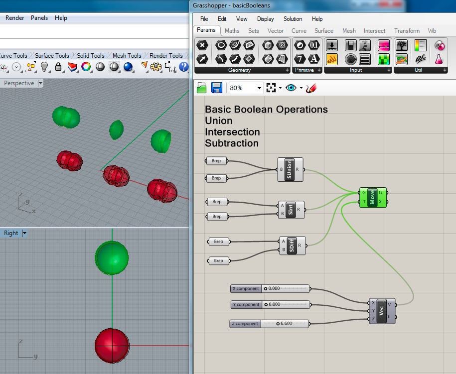
9. CONSTRUCTION OF SOLIDS USING BOOLEAN OPERATORS WITHIN GRASSHOPPER
Download the Rhino file booleanSheres.3dm and the Grasshopper file booleanSpheres.gh from the classes server ARCH2710-671--Mark-Fal2014\examples\booleanSpheres. Open the file booleanSheres.3dm from from Rhino and then the accompanying fie booleanSpheres.gh from within Grasshopper.
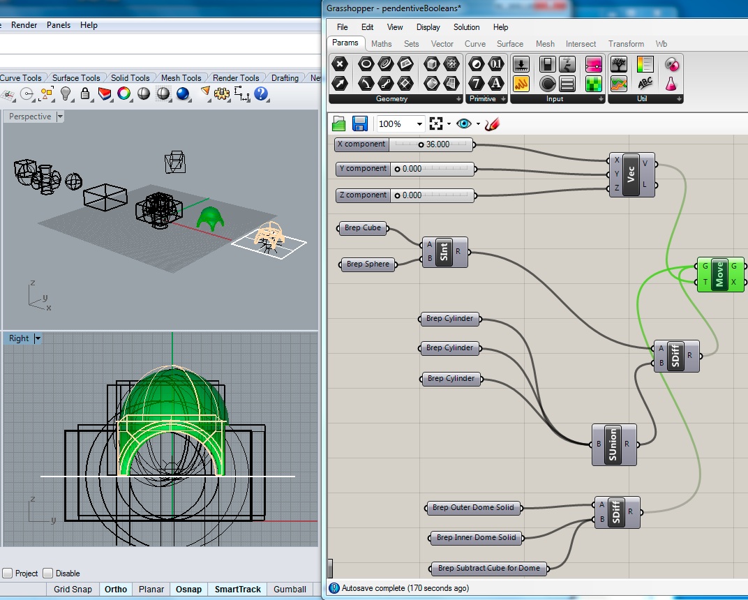
10. CONSTRUCTION OF A PENDENTIVE USING BOOLEAN OPERATOR WITHIN GRASSHOPPER
Download the Rhino file pendentiveViaGH.3dm and the Grasshopper file pendentiveBooleansViaGHtest.gh from the classes server ARCH2710-671--Mark-Fal2014\examples\pendentiveKit. Open the file pendentiveViaGH.3dm from from Rhino and then the accompanying fie pendentiveBooleansViaGHtest.gh from within Grasshopper.