
COMPUTER
AIDED
ARCHITECTURAL DESIGN
Workshop 9
Notes,
Week of October 27, 2014
Introduction to Animation, File Transfer From Rhino, Dynamics, Keyframing
Animation KeyFraming is one of the more common techniques for describing the movement of objects within a 3D model. Dynamics introduces physics simluations which can also used to facilitate movement.
Part I: Transfering Geometry from Rhino , Dynamics
1. Create a Rhino File with a ground surface, box, sphere, truncated cone and V-Ray sun light, and create the setup below using methods covered in earlier tutorials. Create separate levels for a) the ground surface, b) the box, sphere and truncated cone, and c) V-Ray sunlight. Or, reuse the Rhino file developed at the end of the tutorial developed for Workshop 9.
2. Within Rhino use the "File/export selected"command, select the geometry within the file, and export it to an external Motionbuilder "fbx" file (filmbox) with the default options.
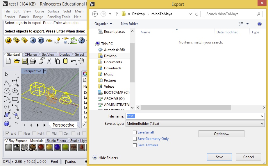
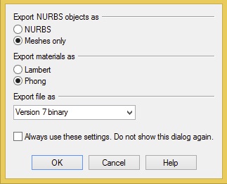
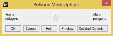
The FBX export default options should be evident in two sequential dialog boxes. Use the "simple controls" option fo rthe second dialog box:
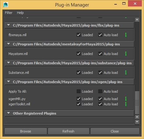
3. Launch Maya. Go to the menu item "Windows/Settings-Preferences/Plugin-Manager" and ensure that check-box is selected for the plugin titled "fbxmaya.bundle".
5. Next, go to the menu item"File/Import", set the type file to "All files", and import the fbx file exported in step 3.

4. Within Maya, select the "4" key to turn on wireframe view mode, and select all the objects.
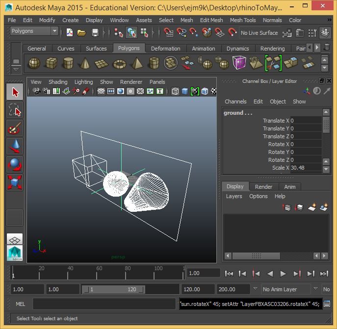
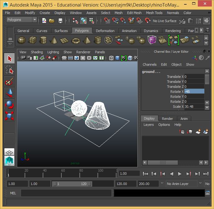
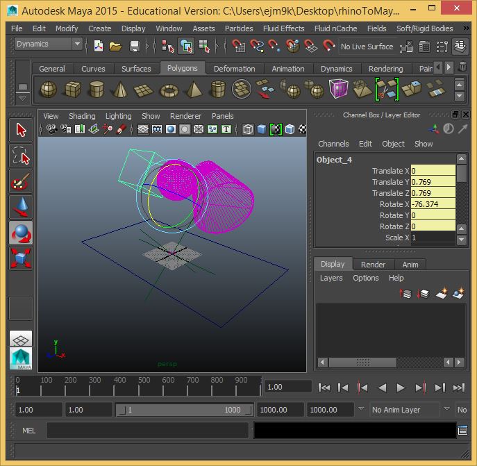
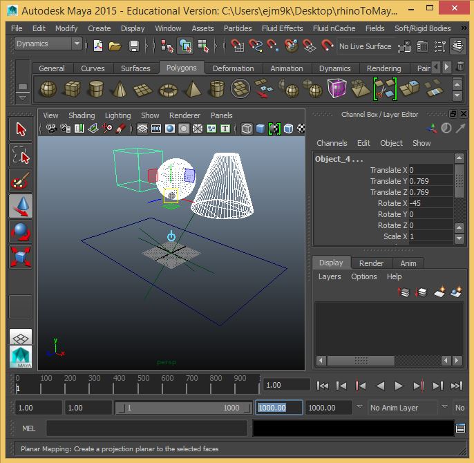
5. Note that within default coordinate system in Rhino, the Z-axis is vertical. However, within the default coordinate system within Maya, the Y-axis is vertical. Rotating the objects 45 degrees witin Maya transposes the geometry so that the vertical direction is correctly oriented. Therefore, select the geometry within Maya. It it isn't already showing, open up the "channels" dialog box by selecting the icon in the upper right-hand corner of the Maya application Window. Now within the Rotate X channel, enter the value -45. This should restore the geometry to the appropriate upright position.
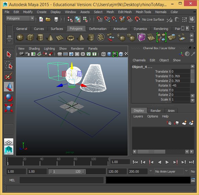
6. Select the three solid objects within Maya as well as the "move" tool on the left-hand side, and using the up-arrow (yellow color) on the move tool, reposition the objects above the ground plane. The move tool is similar to the "Gumball" tool in Rhino.
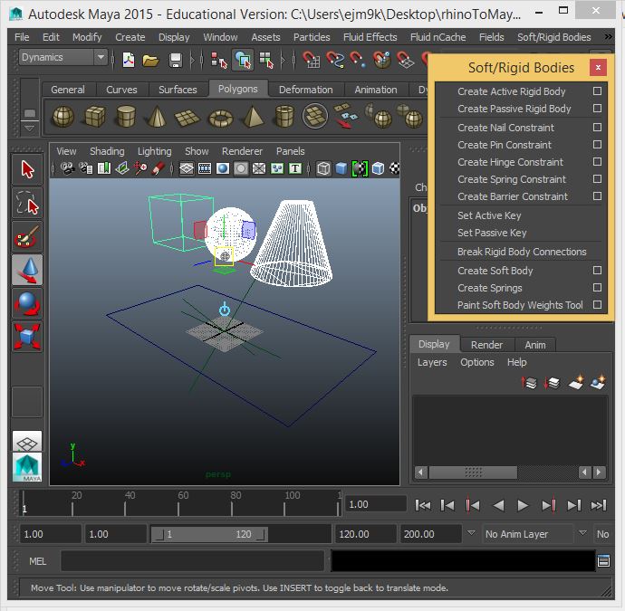
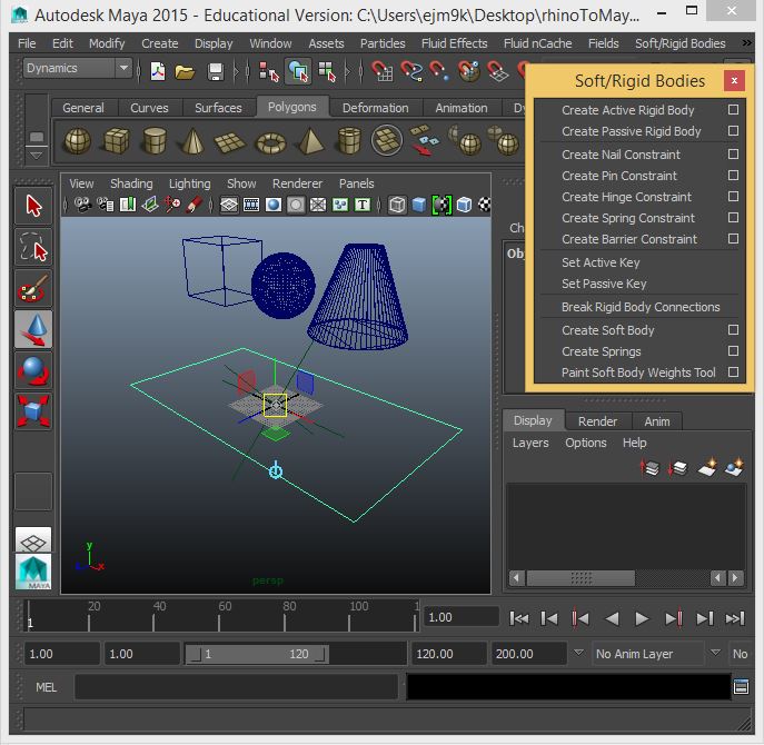
7. Use the pull-down menu in the left-hand corner and change the active module to dynamics. Next, go to the "Soft/Rigid Bodies" menu, and with the three objects still selected, choose the option "Create Active Rigid Body".
9. Next, select the ground plane, and returning to the menu "Soft/Rigid Bodies" select the option "Create Passive Rigid Body".
9. Next, the "rotate" tool is just below the "move" tool on the left-hand side of the screen. Select it and rotate the cube and the truncated cone so that they are slightly off vertical axis.
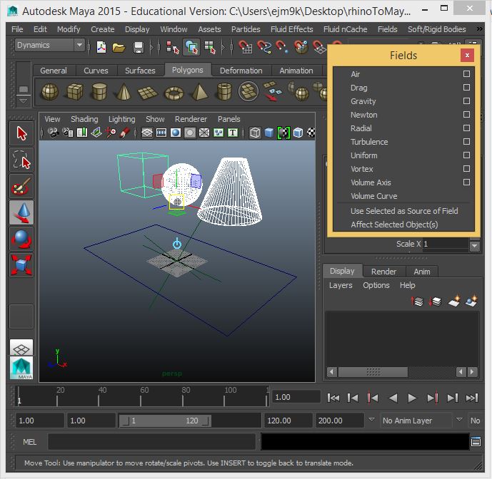
10. With the cube, sphere, and cone still select, go to the menu item "Fields" and select the "Gravity Field".
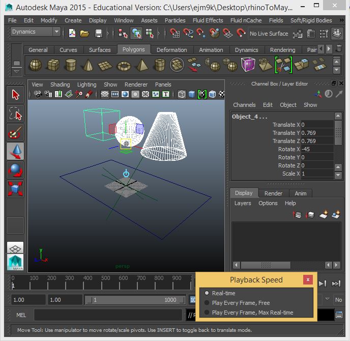
11. To expand the number of frames, select the number "120" on the timeline at the bottom of the Maya window, and change the number to 1000 to expand the number of visible and total frames in the animation sequence.
12. To control the playback speed, right-click on the timeline at the bottom of the application window, and set the playback speed to "Real Time".
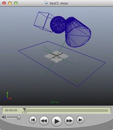
Play the animation and see the three solid objects fall onto and collide with the plane surface, bouncing a few times. The result should look similar to the following (select the image to play the animation):
Part II: Basic Object Creation & View Control
Create/nurbsprimitives/sphere
Drag to create size interactive/or single click for default values
VIEW CONTROLS
MODIFY SPHERE USING CHANNEL BOX
CREATE BOX USING HOT BOX
CREATE CONE USING SHELF
CHANGING ATTRIBUTES OF OBJECT WHILE CREATING IT
CHANGING ATTRIBUTES OF EXISTING OJECT
ATTRIBUTES OF SURFACE TORUS
POLYGONS
CHANGING POLYGON PRIMITIVE ATTRIBUTES (Varies per object type, not all attributes appear on all objects)
TEXT {SKIPPED DURING ACTUAL WORKSHOP}
NAMING OBJECTS
PIVOT POINT
PART II: SETTING UP A PROJECT FOLDER
PART III: SIMPLE KEYFRAME ANIMATION