COMPUTER
AIDED ARCHITECTURAL DESIGN
Workshop
1 Notes,
Week of August 24, 2015
Initiating
a
drawing in Rhino and Graphics Primitives
1.
Opening Rhino :
Programs/Architecture
and 3D Modeling/Rhinoceros 5.0/Rhinoceros 5.0
2.
Opening and saving a new file
:
Opening Rhino
will automatically generate a new file. Choose File / Save and choose
the directory where you want it to be saved to.
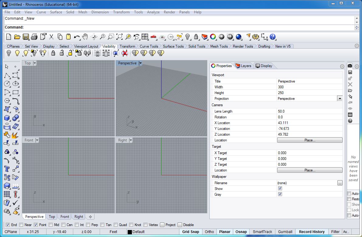
The
file will
open with 4 viewing windows –each show a different views of
model
space (Top, Perspective, Front, Right)
Use Zoom
Extents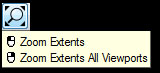 (small
magnifying glass icon) to see all elements of
drawing. Hover over the icon to see additional options for this command.
(small
magnifying glass icon) to see all elements of
drawing. Hover over the icon to see additional options for this command.
Double
click on any of the viewport titles to maximize the view. Double click
again to return to the four viewing windows. Left clicking on the mouse
will activate the current view. A right click will display options for
each viewport.
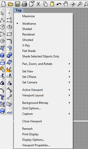
You
can
also change the view type by selecting Set
View here.
3.
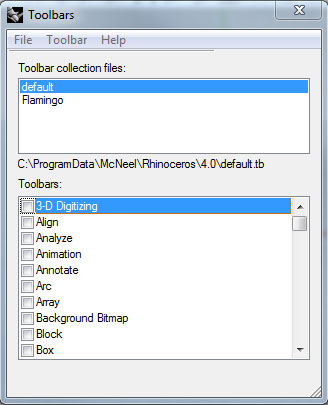
Turning on standard tool bars (should be on by default):
Select: Tools
/ Toolbar Layout and
each of the following should also be
selected on by default: Standard,
Main1, Main2.
To
save a
customized toolbar collection, click on the check box for each toolbar
and File / SaveAs to save the .tb file to your folder.
4.
Establishing scale units:
- To
bring up
the Rhino Options window, click on: File / Properties
- Select: Units
- Model
Units pick: feet, meters, etc.
- Under
Distance Display, select Feet & Inches
- Display
precision by default is set to 1.00.
5.
Establishing Reference Grid:Setting
a Grid to scale
units:
- To
bring up
the Rhino Options window, click on: File / Properties
- Select:Grid
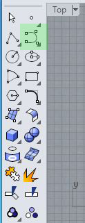
6.
Drawing graphic primitives
(all tools in Main1 and Main2 tool
palettes,
screen-right)
a)
COMMAND
PROMPT: type in the tool in the command prompt. This will bring up
additional options per tool. Click on the option or use the shorthand
key (underlined) to modify the tool accordingly. To use the default
dimensions/controls, use the right mouse button. NOTE: Pressing the
spacebar or rightclicking is equivalent to "Press Enter".

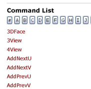
To
see a full
list of all command prompts, go to Help / Command List...
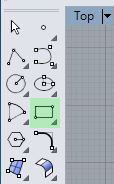
b)
ICONS: For
any icon with a triangle in the lower right hand box (  ),
click and hold down left mouse button over the icon to see tool
subsets. Click/drag on this new window to tear away the linked window.
Hover over any icon to see options for a left/right mouse button click.
),
click and hold down left mouse button over the icon to see tool
subsets. Click/drag on this new window to tear away the linked window.
Hover over any icon to see options for a left/right mouse button click.
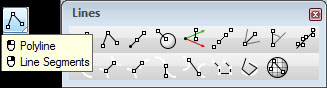
- Polylines and
lines (line through points, etc.)
- Circles (can
be drawn by selecting method center,
edge, etc.)
- Arcs (can be
drawn using similar methods as circle)
- Polygons
(can
be
drawn using similar methods as circle)
- Points
(single, multiple, extract, etc.)
- Curves
(control point curve, interpolate curve, etc.)
- Exact values
may be entered in the command prompt.
TIP:
You can
use the spacebar or right click on the mouse to select the previously
used tool. (i.e. to quickly draw points or circles successively).
7.
Using
the Status Bar for Snapping and Ortho controls:
- Snaping to
the grid: select the grid Snap
toggle pane on the status bar
at the bottom of the screen to turn grid snap on [in bold] or off. The
points on the grid will constrain drawing ability. F9 on the keyboard
quickly turns this mode on/off.

- Snapping to
other points: Select Osnap
toggle pane on the status bar to
turn object snap on [in bold] or off. This will bring up various
options for object snapping. Check off your desired snaps. Pressing the
Alt key will temporarily suspend object snaps.

An
alternate
and more detailed way to do this will be explored in the next workshop.
is to select the icon in the standard toolbar (towards the top of your
screen) to see other methods of object snapping.
- The Ortho
toggle pane locks the cursor's direction of travel. Additional
directional locks will be explored in the following workshops. F8 on
the keyboard quickly turns this on/off.
- The Planar
toggle pane limits successive picked locations to the same construction
plane elevation as the previous location.
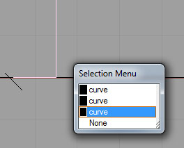
8.
Deleting objects:
Select
object(s) to be deleted. If objects are overlapping, the selection menu
window will appear to specify object. Toggle through the menu to find
the desired object. Then use the delete button on keyboard.
9.
Using
the view icons in the standard toolbar at the top of your screen:
 Pan
View
(Arrow): allows view to be repositioned allow a vector.
Pan
View
(Arrow): allows view to be repositioned allow a vector.
 Rotate View:
may be used to move about the construction.
Rotate View:
may be used to move about the construction.
 Zoom in
, zoom out
Zoom in
, zoom out
 Window
Area: defines view window for zooming in
Window
Area: defines view window for zooming in
 Fit
view: returns to window what has been constructed in the model space.
Fit
view: returns to window what has been constructed in the model space.
 Zoom
selected objects
Zoom
selected objects
 Undo
view changes. Press and hold left mouse button to see additional
tool subsets.
Undo
view changes. Press and hold left mouse button to see additional
tool subsets.
 Change
View Layout. Press
and hold left mouse button to see additional tool
subsets.
Change
View Layout. Press
and hold left mouse button to see additional tool
subsets.
 Set View
(front, top, etc.). Press
and hold
left mouse button to see additional tool
subsets.
Set View
(front, top, etc.). Press
and hold
left mouse button to see additional tool
subsets.
10.
Saving file
Rhino
provides
a few ways to save a file:
File
/ SaveAs: saves
file to desired location.
SaveAs
Template: saves current model
as a template file.
SaveSmall: saves
geometry objects
without render or analysis meshes (good for reducing disk space, or for
emailing, etc.)
IncrementalSave:
If you would like to save
iterations of model, this will save
sequentially numbered versions. Edit / undo / redo will allow you
return to previous work, but is of limited value.
To
turn
automatic Autosave on: To edit this setting, go to Tools / Options.
Under Rhino Options, select Files
and under Autosave, adjust
accordingly. Rhino
autosaves every 20 minutes, but this can be adjusted here.
11.
Choosing Layers:
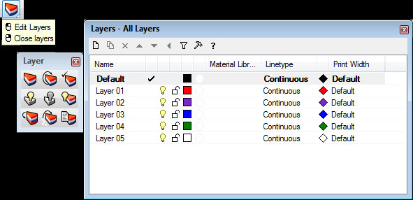
Click
the
colorful pie wedge icon on the top toolbar to bring up the layers
window. You can dock it anywhere on the screen. Double click on a layer
to make any layer active, and turning the lightbulb icon on/off will
control visibility of that layer. Using layers allows parts of the
model to be turned off or on and will be useful for assigning
attributes, such as assigning colors of lines or linetypes.
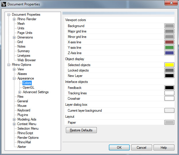
12.
Adjusting Colors of Viewport, Selected Objects, etc.
Go
to File /
Properties, or Tools / Options, and select Colors to bring
up options to set background colors, selction colors, etc.
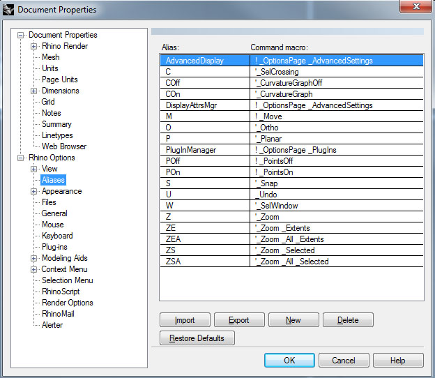
13.
Aliases for the command prompt:
If
you prefer
to create shortkeys for the command prompt (for example, typing in"C"
instead of "Circle" and "L" for "Line"), this can be done under Aliases
in the same window. You can import your own .txt file to define
shortkeys. Some predefined ones can be found online.
13.
History - Associative Geometrical Modeling Preview
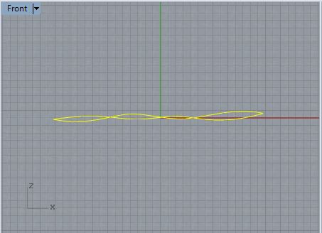
Using
the create control
point curve tool, create two control point curves along the X
-
axis in the X-Z plane through the front view window with roughly the
same end control points but otherwise different.
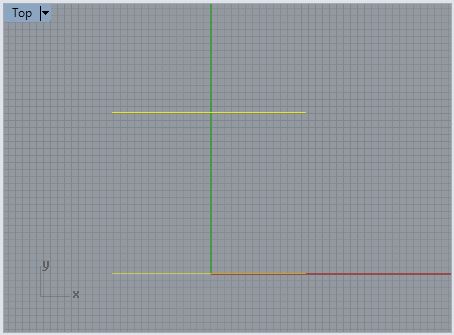
From
the top view , move
one of the curves along the negative "y" axis such that they appear as
follows:
On the lower right-hand side of the Rhino application window, turn on
the "Record History" button":

From within the perspective view window, preselect the two
curves
and then use the loft tool with its default settings to
generate
a lofted surface between the two curves:
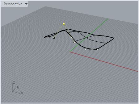
From
within the
perspective view window, move either of the two curves, and the surface
will be modified accordingly. Here, the "history" of the
surface
is retained such that it is impacted by any modification to the original curves. In the image
below, the curve along the x-axis was moved vertically, and the surface
is modified accordingly:
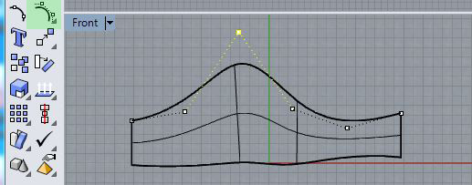
Or, going back one step further in the construction sequence, select
the curve, then select the control point tool with the left mouse
button. In the front view window move one of the control points on
the curve vertically. Again, the surface is modified accordingly.
14.
History
- Associative Geometrical Modeling Preview Continued
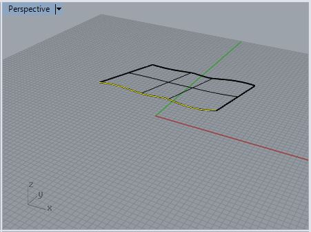
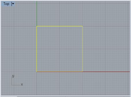
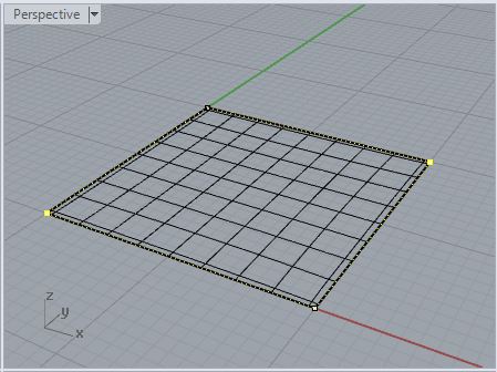
Using
"history" in a
similar way, use the "rectangle: corner to corner" tool to build a
square in the "top" view:
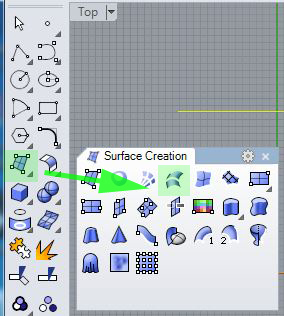
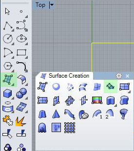
Turn on the "history" button, and from the "surfaces" tool palette,
create a patch surface:
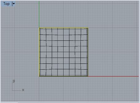
From the "perspective" view, the patch surface also appears to be flat:
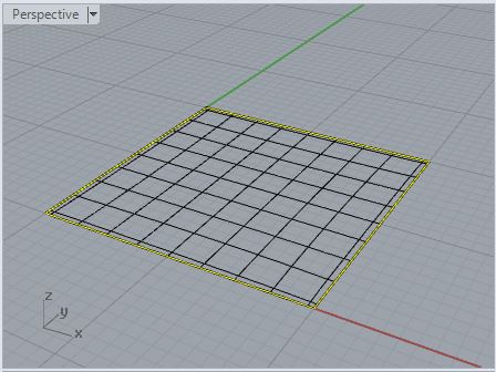
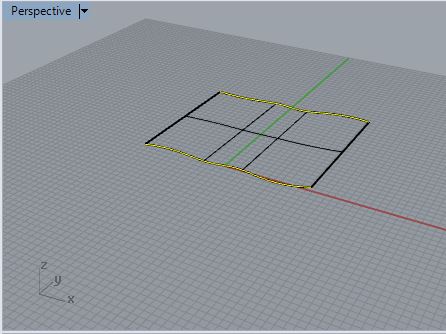
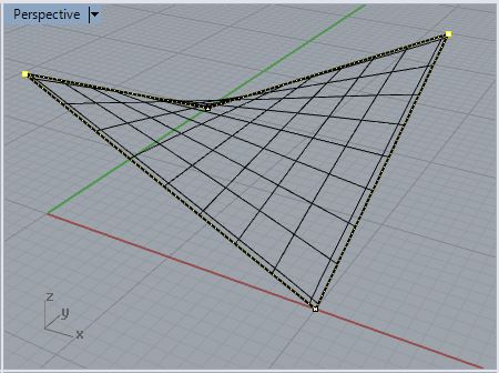
Now, similarly to the case of the lofted surface above, turn on the
control points of the corner by corner rectangle, move them vertically upward
from the "front" view, and you determine a simple saddle shape:
15.
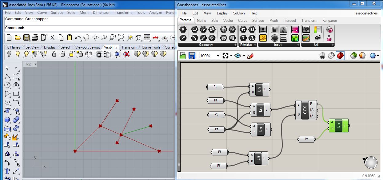
Extracurricular example: associative points and lines via Grasshopper
(you do not need to be able to know
this technique, at least at this point in the semester):
[Note: when the
steps below are completed, they result in creating the Rhino file associatedLines.3dm
file and Grasshopper file associatedlines.gh. This
files are linked here for reference. However, this example is just a preview of techniques we will look at later in the semester. You
do need to master the techniques involved or know Grasshopper at least
at this point in the semester.]
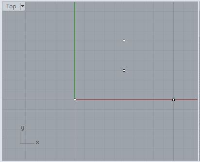
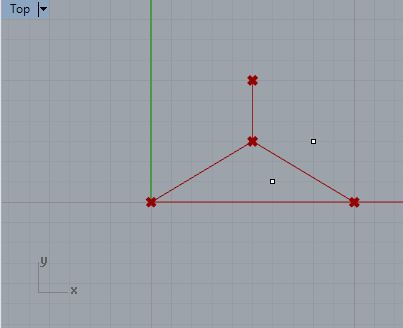
Within
Rhino
create 3 corner points of an implicit triangle and a fourth point in
its center.
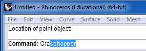
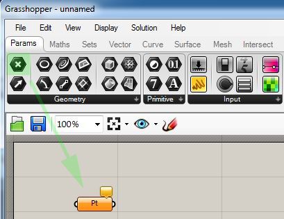
At the command prompt, type in "Grasshopper" to open Grasshopper.
Within Grasshopper, go to menu "File/Nnew Document". Next, select a
point parameter icon and with the left-mouse button drag it to the "canvas" window.
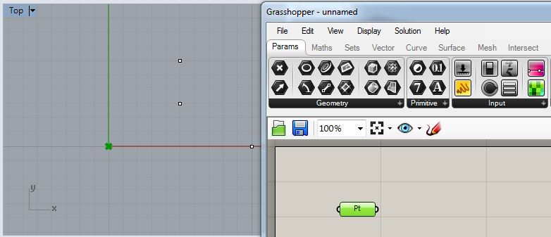
Right-click on the point parameter inside the canvas window, select the
"set" menu item, and then select the lower left-hand corner point
previously created in Rhino. In the illustration below this results in
the
point icon in Grasshopper being associated with the point at the origin in Rhino:
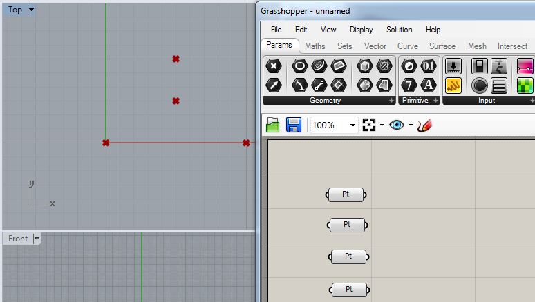
Do the same by adding three additional point parameter symbolss and connecting them with the remaining
thee points in Rhino.
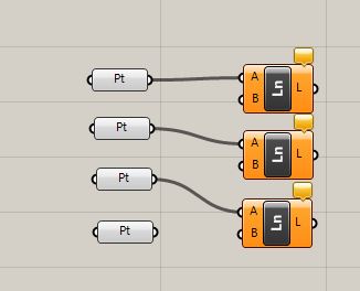
Within Grasshopper, go the the "curve" task, and drag the "line" icon below into the "canvas" window three times as illustrated below.
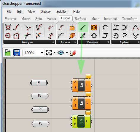
Drag an arrow from the output port each of the three corner points symbols in Grasshopper to the input port "A" of a corresponding line symbol:
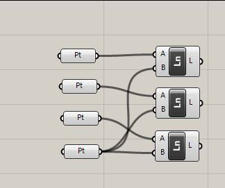
Drag the output port of the centerpoint in Rhino to the input port "B" of
all three line symbols.
Return to Rhino and move any of the original points and see what happens. Note that the
lines are redrawn relative to the movements of each point.
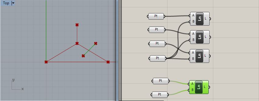
Now add two points inside Rhino at locations that straddle to either
side any one of the lines, such as the lower right-hand line below.
Within Grasshopper, create two additional point symbols and one line symbols using the methods
described above to determine a line between the two new points.
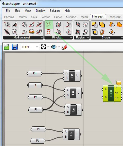
Continuing with Grasshopper, go to the "intersect" task, and
drag
an "intersect line" symbol into the "canvass" windows:
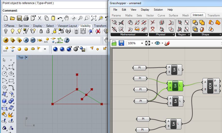
Now, drag the output ports of the two intersecting lines, to determine
a point that lies at the their intersection.
Now
back
in
Rhino, move the original points and see what happens as the result of
associative connections between different elements.
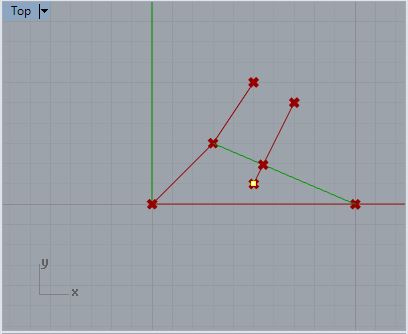
Such a construction can be continued indefinitely. For example, within
Rhino, add a new point, and then within Grasshopper, add a line between
the new point and the intersection point as depicted below. Now back in Rhino, move the original points and see what happens once
again as the result of associative connections between different
elements..