COMPUTER
AIDED
ARCHITECTURAL DESIGN
Workshop 6
Notes,
Week of Sepember 28, 2015 (Preview week of September 21)
INTRODUCTION TO LIGHTING AND RENDERING
These notes will introduce basic lighting and rendering through Rhino Render and continue on to more advanced options using the Rhino plugin for V-Ray. Additional notes are provided on the plug-in for Maxwell for comparative purposes only. They are for optional reading only and the techniques are not required for the class.
PART 1. LIGHTING
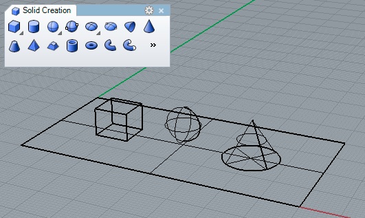
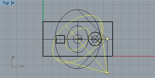
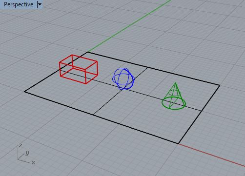
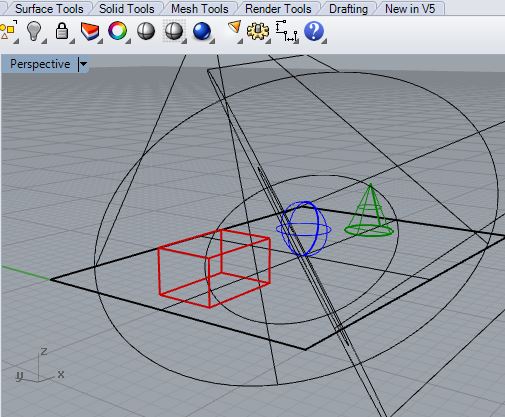
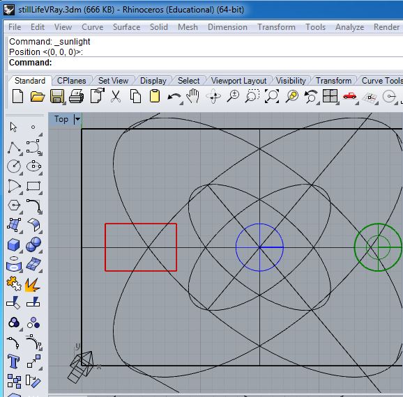
1. Create a Rhino Model with a ground plane surface and three solids as follows:
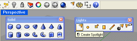
2. Open the lighting icon from upper right-hand side of screen.
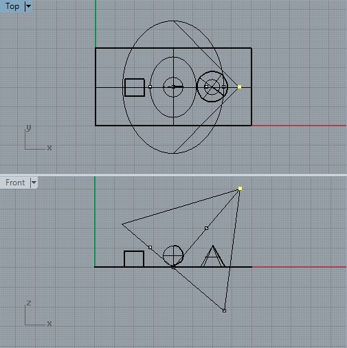
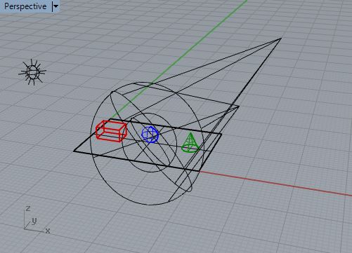
3. Place a spot light in the model from the front view, entering the target and radius first, and then the light location second.
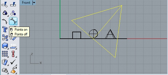
4. Select the light and turn the control points to on.
5. From the top view, move the lighting source position to the +x, -y position relative to the ground plane.
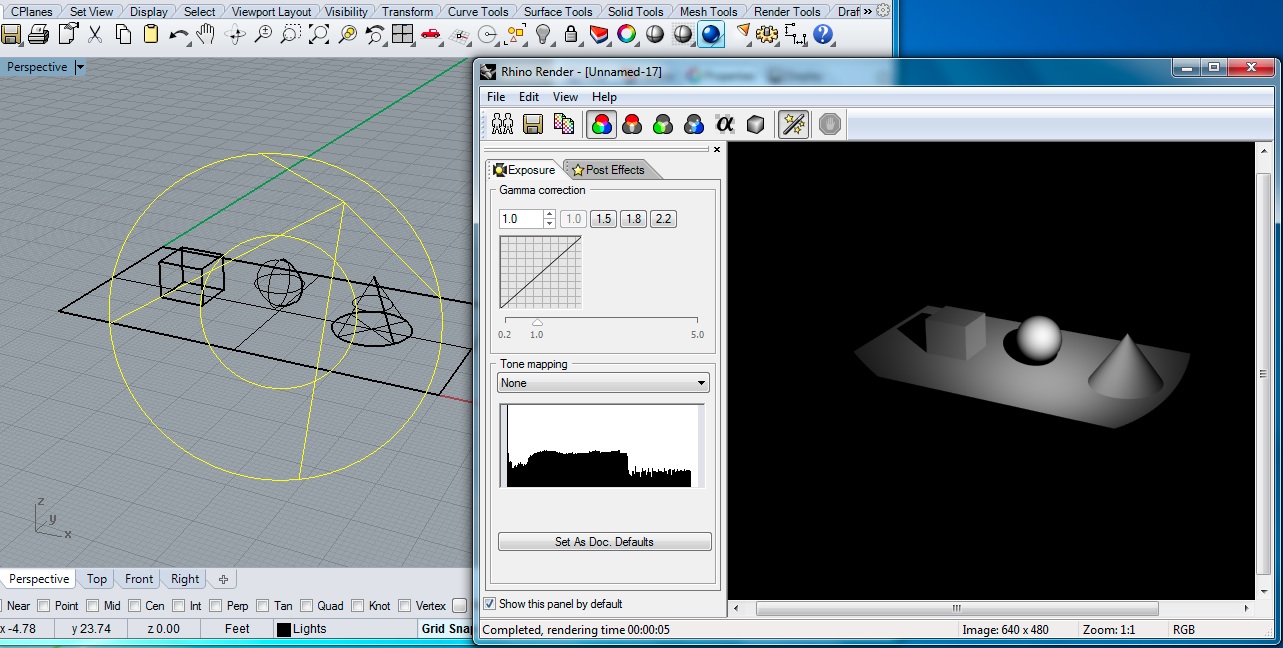
5. Activate the perspective window, select the rendering icon, and render the view.
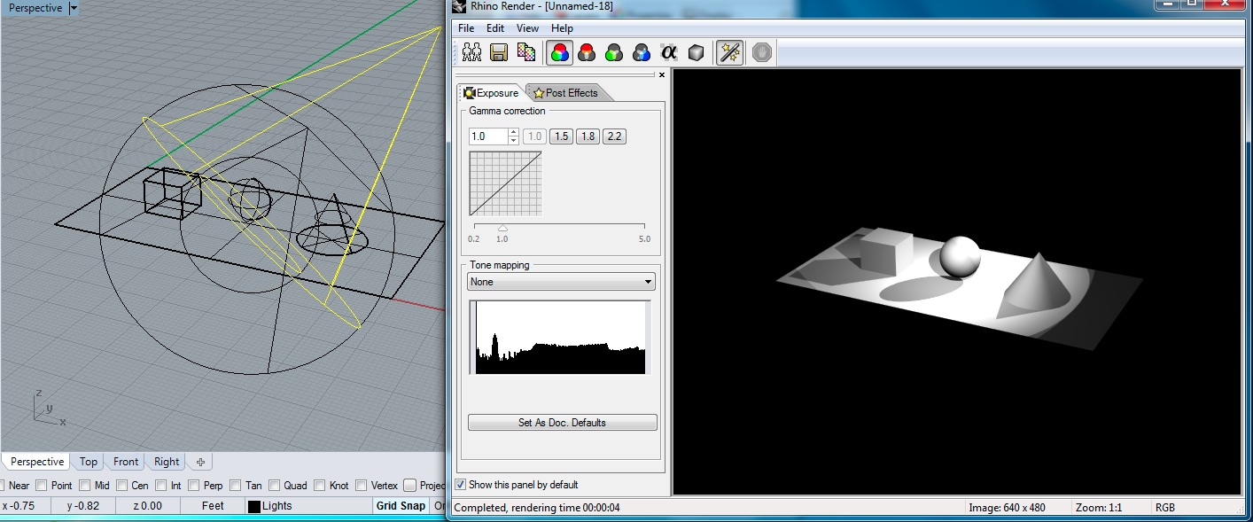
6. Following a similar procedure, create a back spot light pointing towards the center of the model and create a rendering.
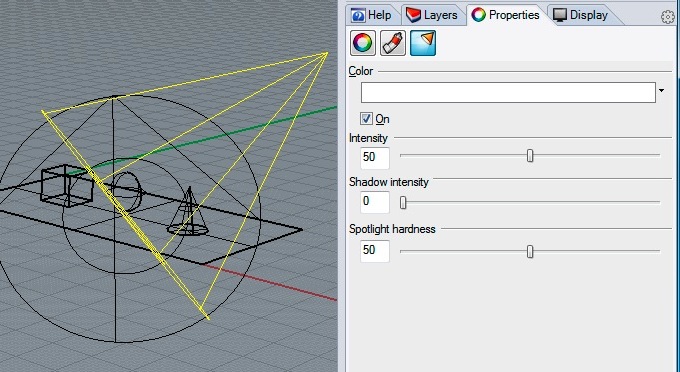
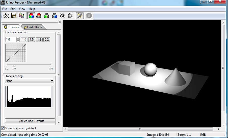
7. Select the properties icon for the back light and reduce the shadow intensity to 0 and light intensity to 50.
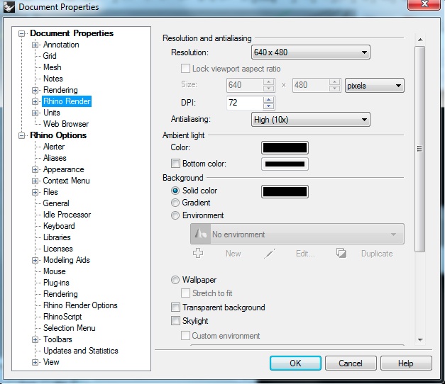
8. To change the background of the rendering, go the the File/Properties menu, select Rhino Render, select Background "Solid Color" and select the color swatch and change it to black. Also, note in the last rendering that there are stair step like lines on geometry running diagonally across screen (they are jagged), such as on the cone and the box. To compensate for this problem, which is called "aliasing", change "Antialiasing" to High(10x) in the same dialog window:
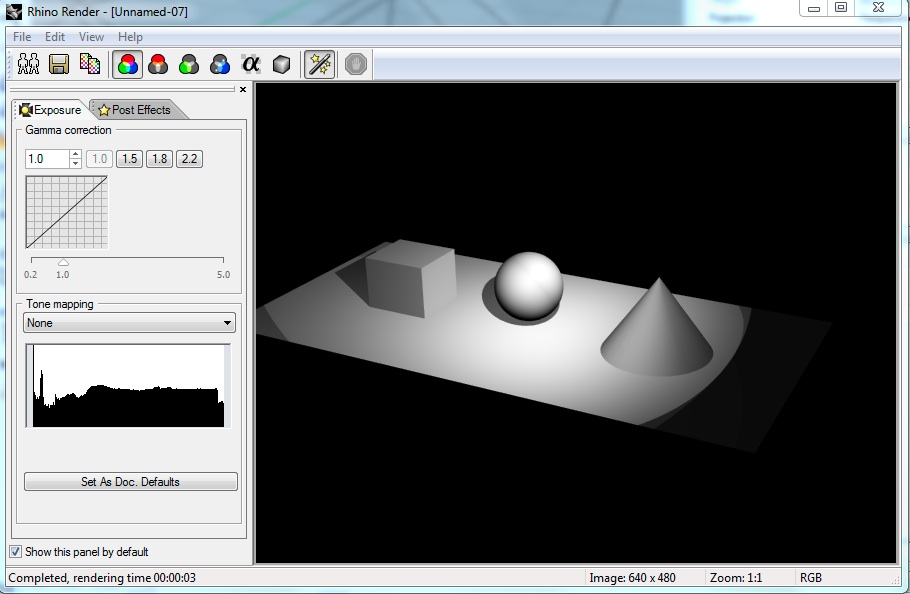
Render the perspective window again and note that the second light is no longer casting a shadow and also that now that there is a black background.
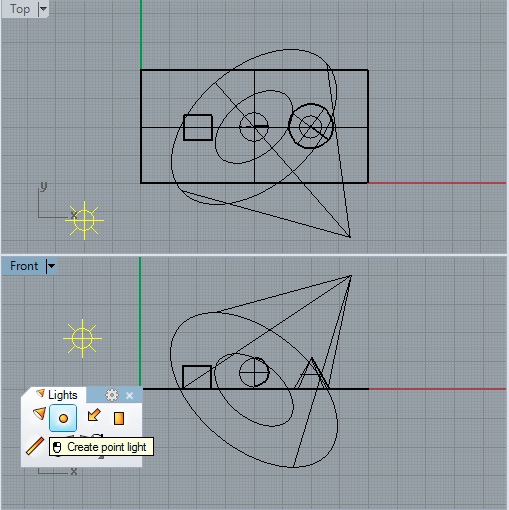
9. Add a point light to the upper left hand corner of the model. Here it is only necessary to position the light source. That is, the point light is an omnidirectional light and doesn't have a target or cone profile. Begin in the front view and continue to place the light in the top view similar to setting the light source locaation for the spot lights.
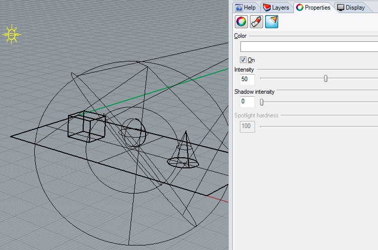
10. Using the properties icon, adjust the shadow intensity of the point light to 0 and change the light intensity to 50 (i.e., 50%).
11. Render the perspective again for a rough simulation of three point lighting.
PART 2. RENDERING
1. You can continue to adjust the antialiasing level by rendering the same model within a more advanced rendeing tool as we will see in a later workshop tutorial.
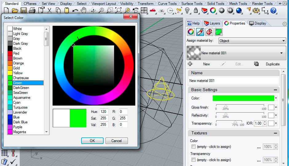
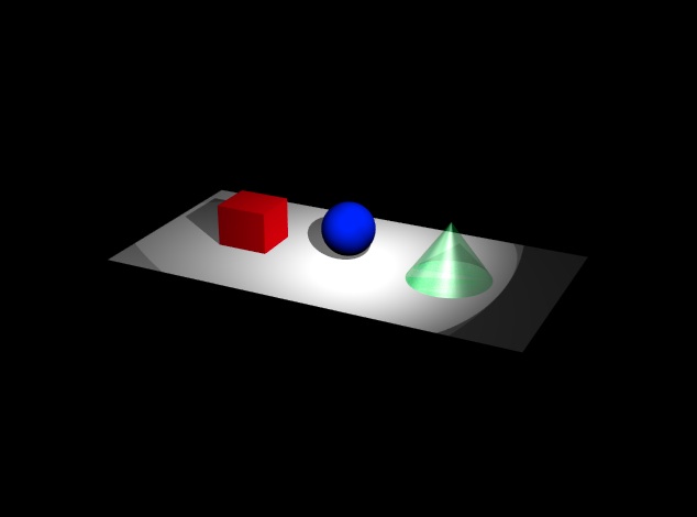
2. Using the same properties icon as before, set the material colors of the box, cylinder and cone to red, blue and green, and also make the cone transparent. Note that the "Material" pull-down tab is active, that the "basic" assign by method is selected, and that for the cone, the transparency value is set to 0.75. Do not select the "Transparency Check Box" which refers to a separate material property.
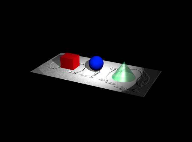
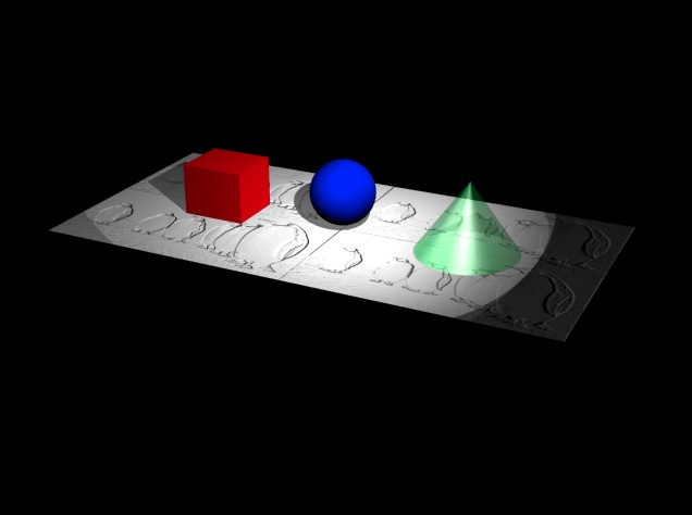
5. Rendering the view to 640 by 480 pixel resolution results in the following jpg file.
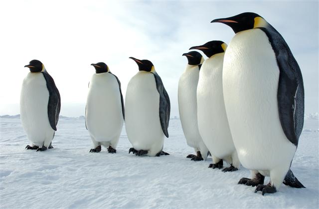
6. Download the image of penguins below by right clicking on it and saving it to your local working folder.
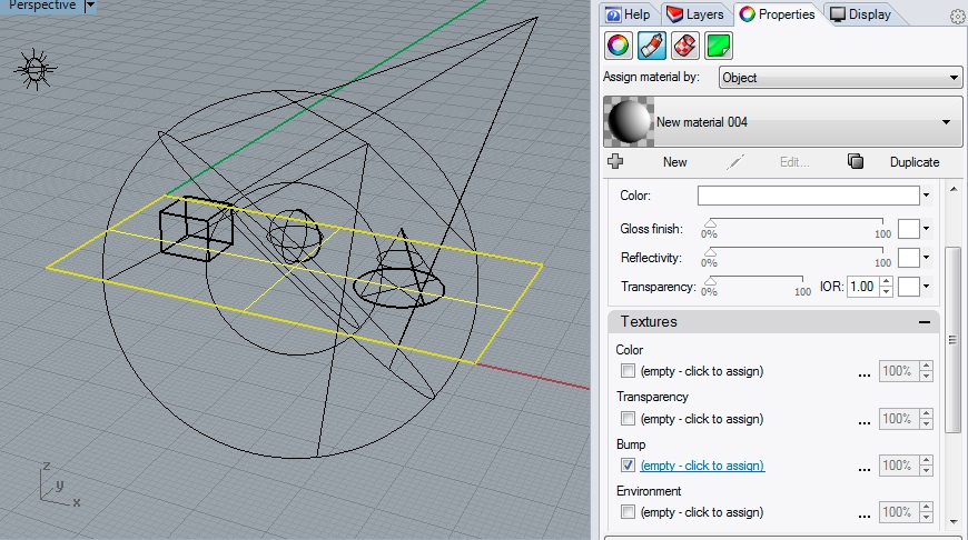
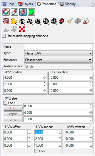
7. Now select the ground rectangle, open up the properties dialog, select the "material" (tube) icon, select the check-box for "Bump" and also "empty - click to assin" link highlighted in blue in the image below. Load the file above through the map file interface.
Render the result.
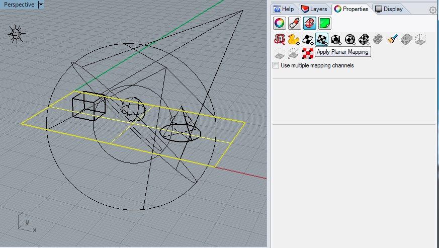
8. Within the same dialog box, go to the texture mapping, which looks like a half roled sheet of paper, and select the planar texture mapping icon.
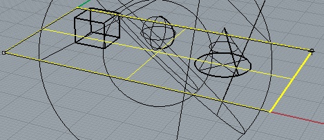
Trace the surface in the ground by a rectangle from the lower-left-hand corner to the upper-right-hand corner.
Now, continuing in the texture mapping dialog box, adust the "UVW repeat" parameters to 2.0, 2.0, and 1.0.
Re-render the image and note that the bump map is repeated twice along each axis.
PART 3: LIGHTING AND RENDERING WITH V-Ray
Part 3 is an introduction to rendering techniques with V Ray. We will introduce basic rendering methods through V Ray for this first tutorial and then return with more advanced treatments of materials and lighting in the workshops to follow.
For a complete
documentation of the V-Ray plugin to Rhino see the V-Ray
For Rhino Plugin Manual
1. To change rendering engines from Rhino Render, go to Menu
item Render> Current Render>V-Ray For
Rhino
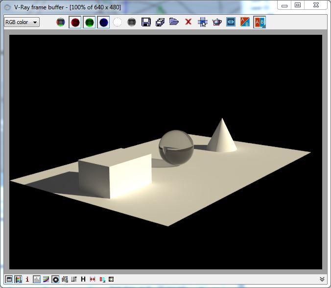
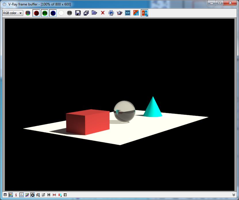
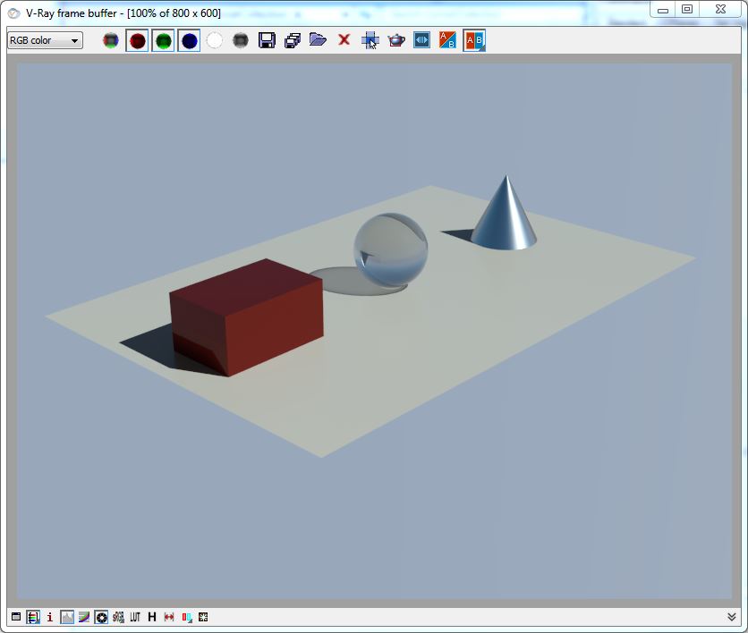
2. Using the same techniques as described above, create a file with a ground plane with three objects, a box, a sphere, and a cone.
3. Create a key light, back light and fill light without determining intensities and other properties.
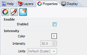
4. Select the spot light in the front right-hand area of the 3D model, and in the properties dialog box, select the "spotlight" icon. Use the default settings, and note specifically that the color is white, intensity is set to 30.0 scalar units (a relative measurement of intensity rather than specific energy units), and that the shadows check-box is on.
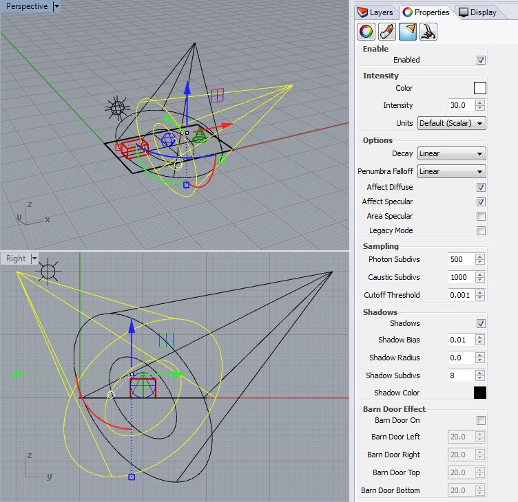
3. Select the spot light in the rear back right-hand side (i.e., the back light). Set the intensity to "15" and uncheck the shadows checkbox.
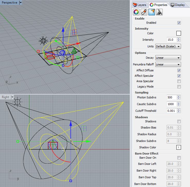
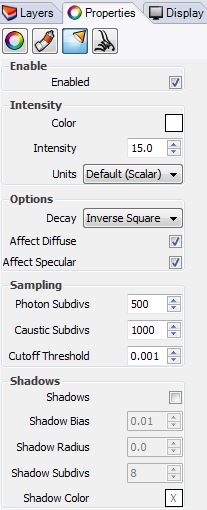
4. Now select the point light, and also set the intensity to "15" and the shadows to off.
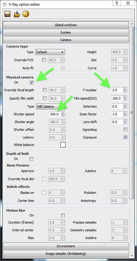
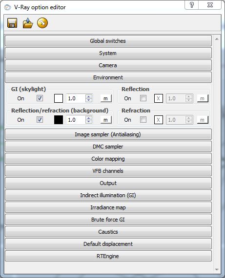
5. Open the menu item "V-Ray/Options" and select the "Camera" tab, switch on "Physical camera", and set the F-number (F-stop number) to 3. The F-number is a number determined by the aperature opening of the simulated camera. A lower number corresponds to a wider aperature opening that increases the exposure to light. A high F-number corresponds to a smaller aperature opening and the lowers the exposure to light. (Note that the actual calculation of the F-number is based upon a the ratio of the focal length to the diameter. That is, F-number = focal_length/diameter. Thus, the greater the diameter of the opening the lower the F- number. )
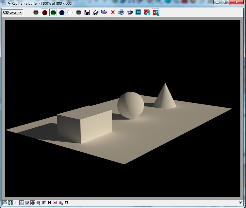
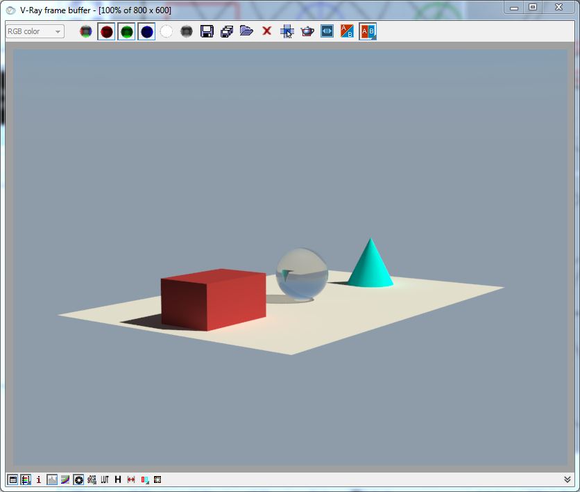
6. Select the "Perspective" window, choose a desirable view orientation, and then select the Render Icon (the blue sphere) and render the perspective view.
If the rendering is too
dark, return to the camera editor, and try lowering the shutter speed
or f-stop number.
Note that a slower shutter speed means that the shutter remains open
and thus
admits more light. Conversely, increasing the shutter speed will
decrease the amount of light entering the camera.
Alternatively, as described previously, lowering the F-number value of
the camera means that the
camera aperature is larger and that the camera will admit
more light. Conversely, a higher F-number correspondends with a smaller
aperature and will decrease the amount of light entering the camera.
However, lowering the F-number may be used to increase the depth of
field, a measure of how much within the view lies in focus. This is
a technique that will be discussed in a later workshop.
7. For another approach, within the V-Ray Buffer Window, turn on the icons in the lower left-hand corner for "show color corrections control", "color corrections level", and "use exposure correction" (see icons highlighted by arrows in lower left hand corner of image below).
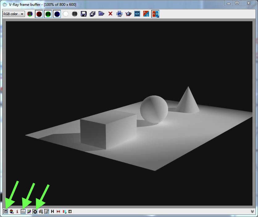
8. The "show color corrections" icon will open the "Color corrections" window. Within the window adjust the left and right "gradiant" slider (the values at the ends of the green arrow of -0.59 and 7.4 in the image below) to produce a desired contrast and brightness level.

9. Within Rhino, select in turn each of the lights in the 3D model, and turn off the "enabled" check-box in order to turn off the light.
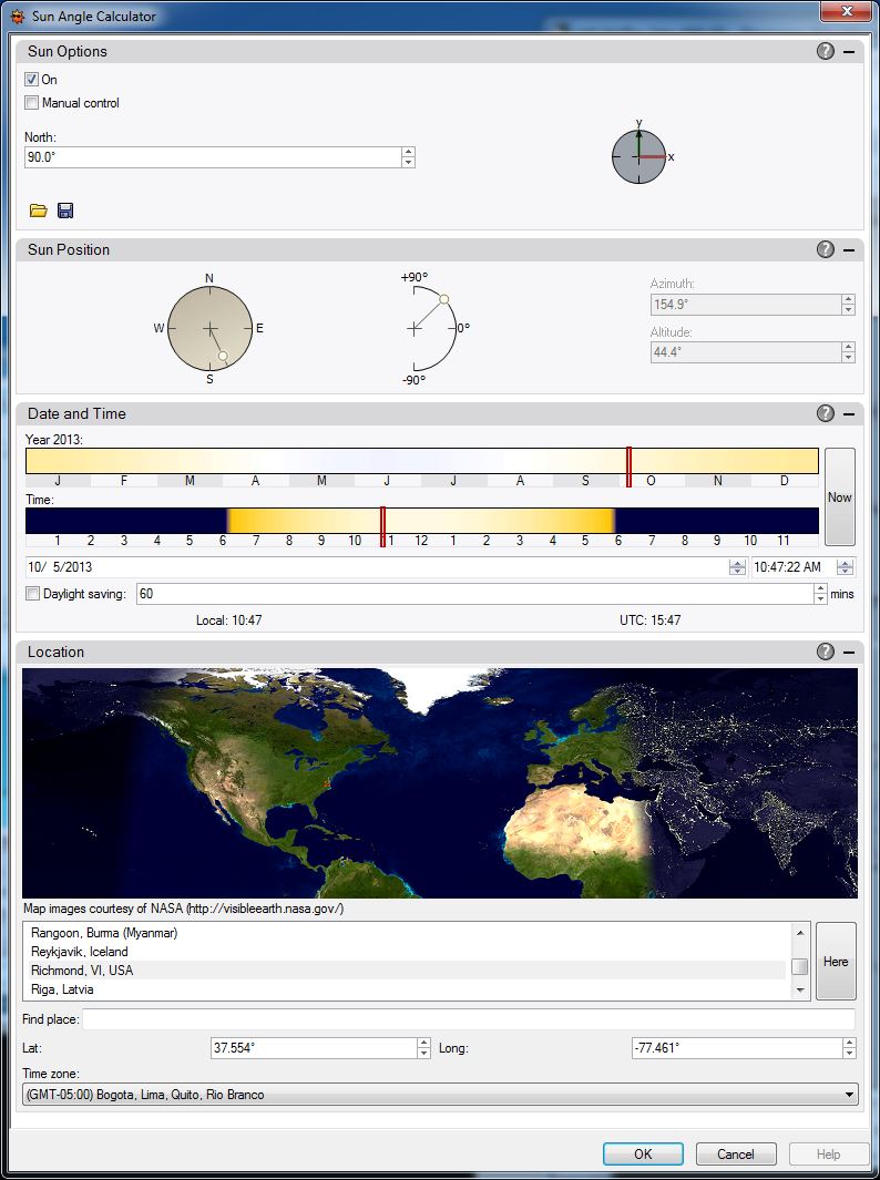
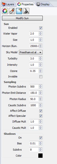
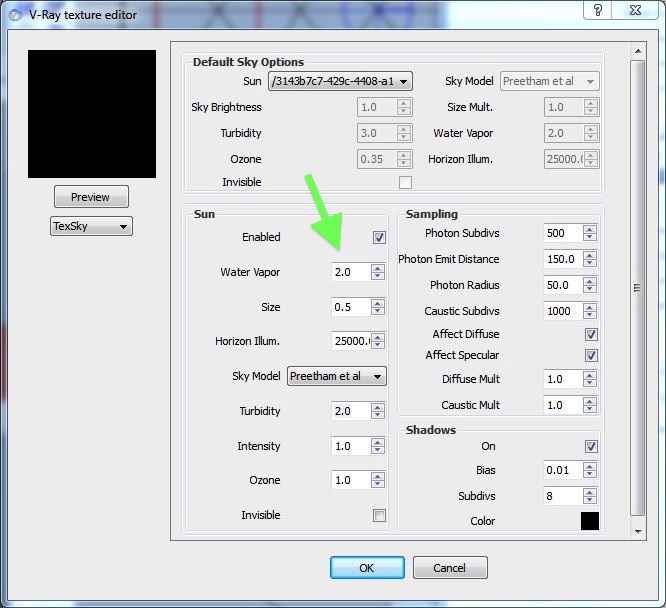
10. Go to Render Tab, and toggle the standard Rhino "sun" symbol to turn on the Sun control panel.
Within the Sun control panel, set the Sun to "On", and determine the time and day of the year, as well as set the location either by picking a city (e.g., Richmond, VA) or entering the exact latitude and longitude.
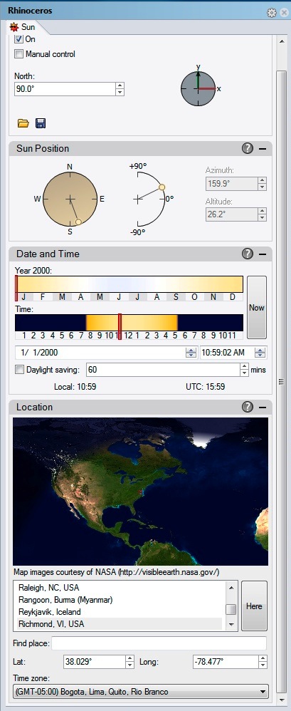
Render to see the impact of the direct sunlight. If necessary, adjust either camera settings and/or the color control curves to arrive at a good light level and contrast. Note that the standard Rhino Sun is tinted to reflect the color temperature of natural daylight.
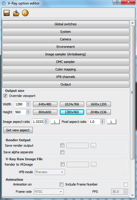
6. Go back to the V-Ray Option editor and open the "Output" tab.
Turn on the check-box for "Override viewport", change the resolution to 1280 x 960 and test render.
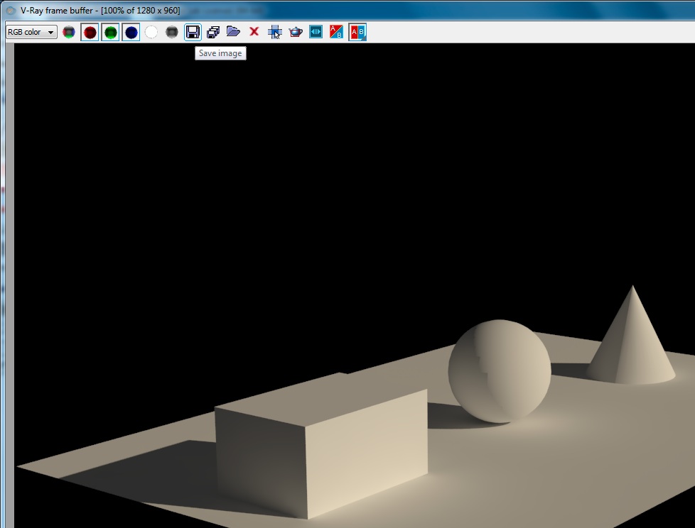
Render again, and within the V-Ray frame buffer, select the floppy-disk "Save image" icon highlighted below, and save the image to the jpg format.
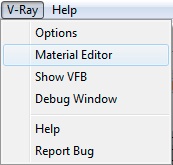
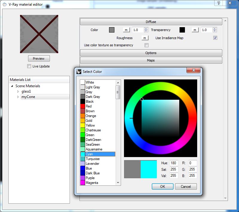
7. To create materials, go to the menu V-Ray/Material Editor
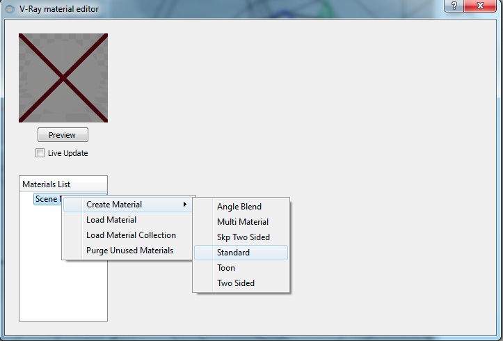
Within the Material Editor Dialog Box, right mouse-button click on "Scene Materials" and select "Create Material > Standard"
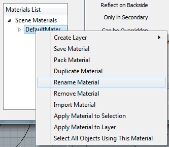
Next, right mouse-button click the text "DefaultMaterial", and rename the material to "glass1"
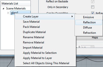
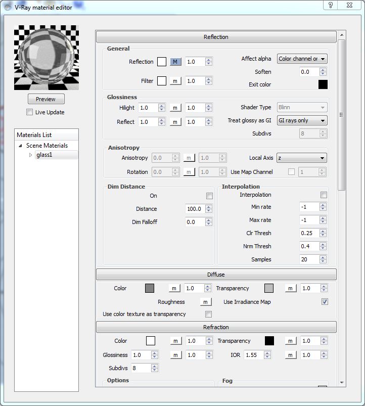
Right mouse-button click on "glass1" and create three layers, one each for "Reflection, Diffuse and Refraction"
Select the "Glass" material and select the "Preview" button to see it. Next, go to the "Diffuse" layer tab, and change the "Transparency" color to Gray.
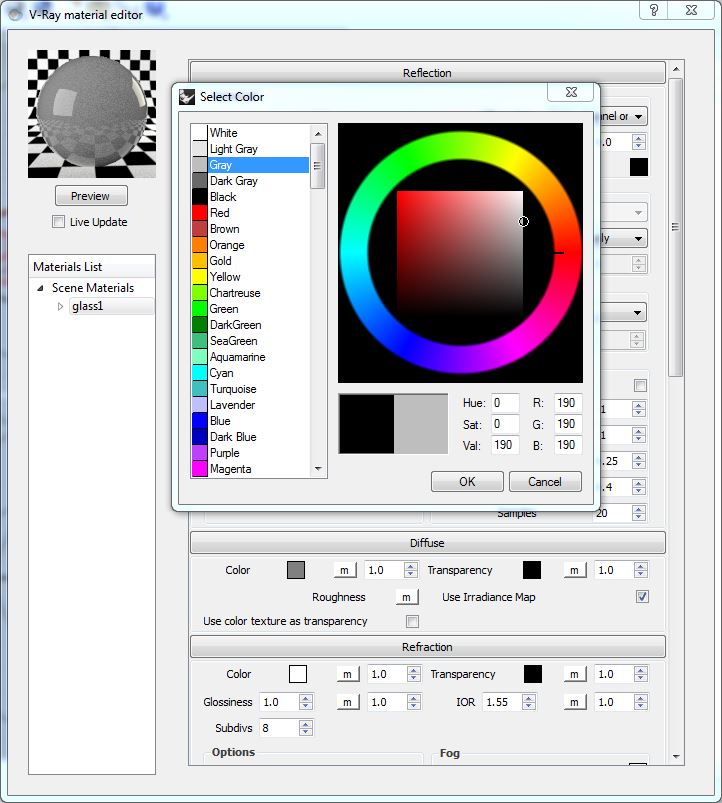
Test the change to the transparency color by again selecting the "Preview" button.
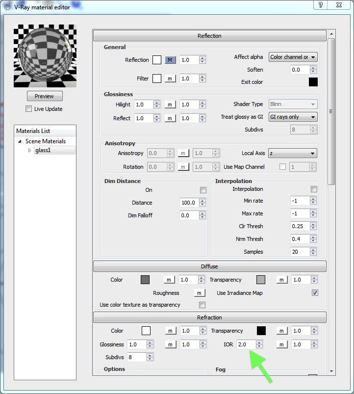
Next, go to the "Refraction" layer tab, change the IOR (Index of Refraction to 2.00), and then once again select the preview Button to see the resulting greater level of refraction.
 f
f
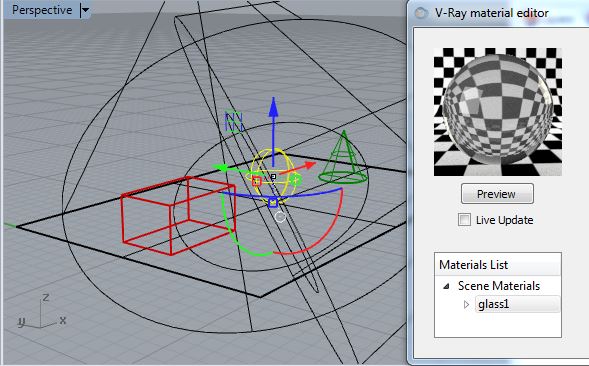
Select the sphere, right mouse-button click on the "glass1" material, and choose the option to "Apply Material to Selection".
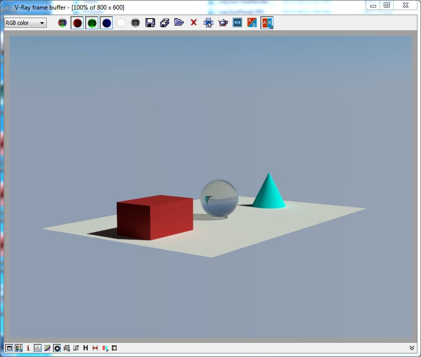
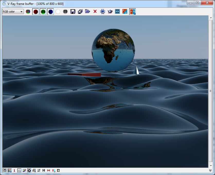
Return to the "Output" tab of the V-Ray option editor, lower the resolution to 640 x 480, and do a test rendering:
Similarly, create a material "myBox", select the Diffuse layer tab, change the "Color" to Brown, assign the color to the box and render the result.
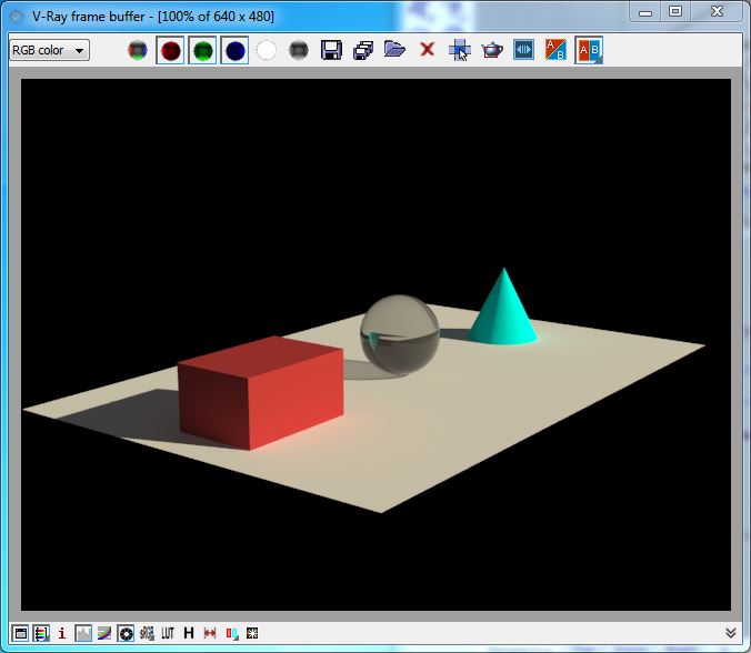
Re-render the perspective view and note the moderately deeper blue color of the sky as compared with the earlier rendering.
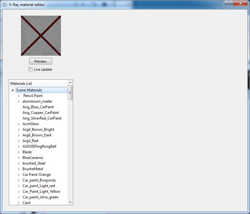
9. Working with a predefined materials library.
With the V-Ray material editor, right mouse-button click on "Scene Materials" (shown below) and select the option to "Load Material Collection" and select the folder for the "Vismat Material Collection" downloaded from the classes server and examples folder. Or, the original source materials can also be obtained free from the V-Ray web site at http://www.vray.com/free_vray_tools/vismat_material_collection/index.shtml.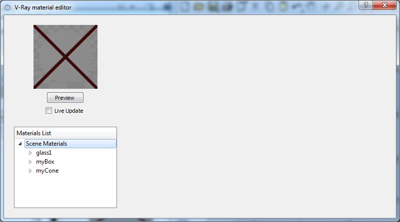
PART 3: LIGHTING AND RENDERING WITH MAXWELL
Part 3 includes a short description of rendering techniques via the Maxwell Plugin. This is an alternative option to V-Ray However, we will be exploring V Ray in greater depth. Here is a brief introduction of Maxwell for comparative techniques and values. This is purely optional reading.
For a complete treatment
of Maxwell's plugin to Rhino see the Maxwell
For Rhino Plugin Manual
1. Go to Menu item Render> Current Render>Maxwell For
Rhino
2. Go to Menu item Maxwell/Plugin Windows>Scene Manager
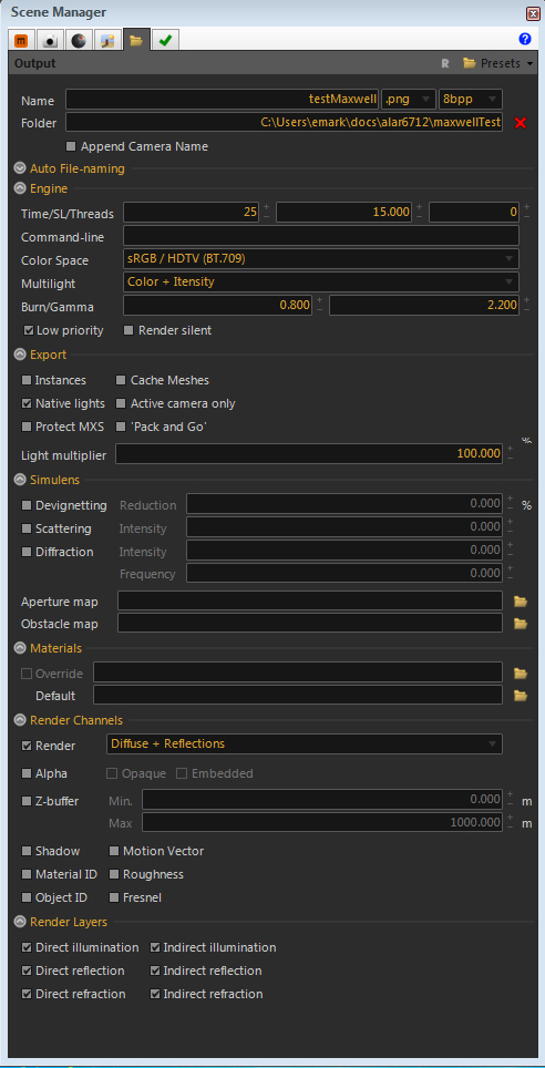
3. Go to Folder Tab
Set Name to testMaxwell.png
Set folder to local folder on "T" drive (or on your local "C" hard drive on a private computer)
Set time to "25" and SL to "15"
Set Light Multilight to "Intensity"("Color + Intensity" is no longer an option)
Set engine to "low priority"
Set render to "difffuse + reflections"
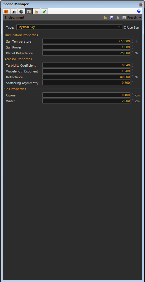
4. Go to Environment Tab
Set type to "Physical Sky"
Select on "Physical Sun"
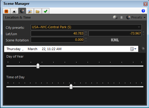
5. Go to Location and Time Tab
Set location to desired place.
Set time to 11 a.m..
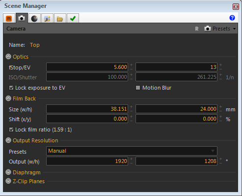
6. Go to camera tab.
Change output resolution to "manual"
Enter output width as 1920 (height will change proportionately). We will modify this later.
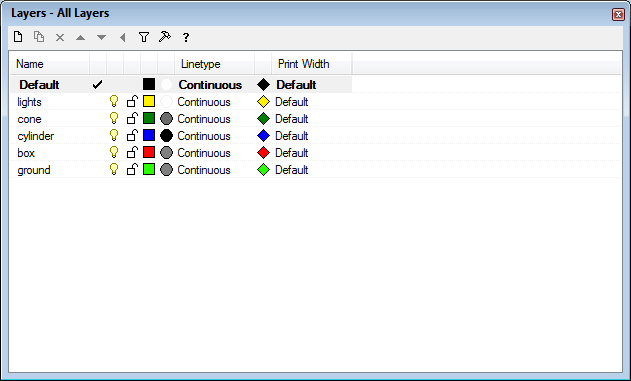
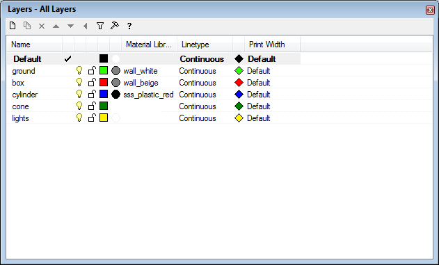
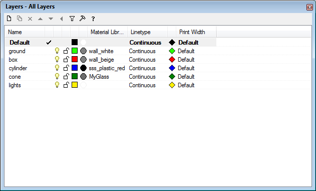
7. Create layers for ground, box, cylinder, sphere and lights and copy objects to each one, changing layer color as desired.
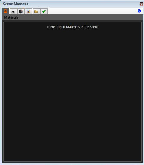
8. Go to materials tab.
Note: the tab is (still) empty. No materials are yet defined for Maxwell.
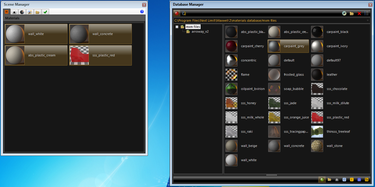
9. Go to Menu item "Maxwell>Plugin Manager>Database"
Drag desired materials from Database manager to Scene Manager
10. In layer manager, go to default material column.
Go to the Material Editor and choose Assign by "plug-in ", and select a Maxwell material via the "browse" option. Note that the "projects" folder on the "classes" server (\\archstore01.arch.virginia.edu) also includes a number of downloaded or student created Maxwell materials.
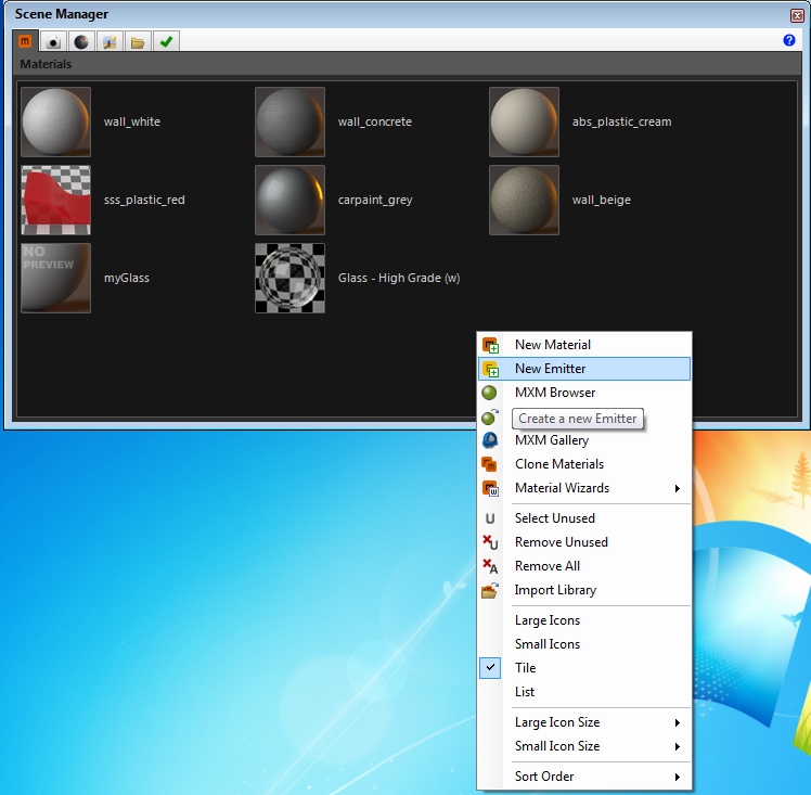
Repeat step for all remaining objects except the cone. For the cone, go to the Materials tab and create a new material using a wizard for glass:
Right-click in the materials window to create a new material.
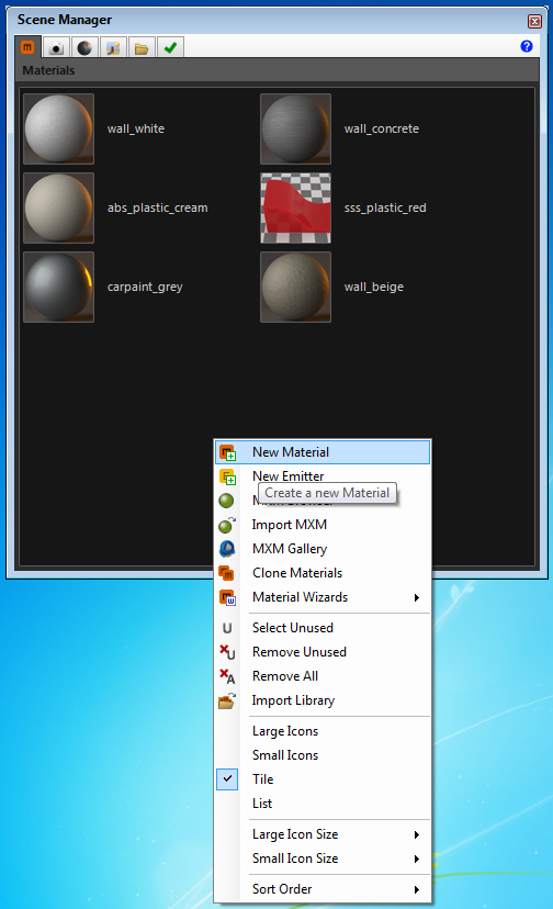
Double-click on the new material.
Name the material "myGlass" - Select the "Wizards" menu and choose "glass/ hight grade".
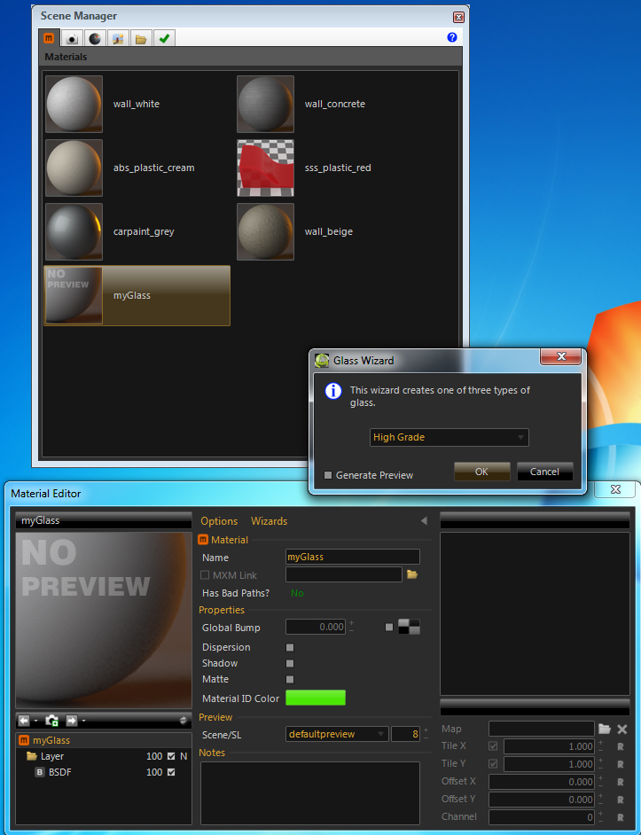
Adjust material properties
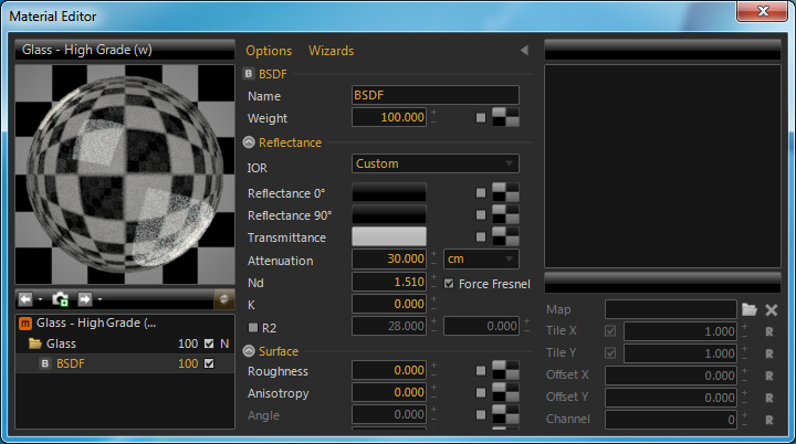
Note Nd = index of refraction - a measure of the speed of light in a material
k = extinction of the wave - absorbtion loss (optional)
More detail on these properties:
http://support.nextlimit.com/display/maxwelldocs/Index+of+Refraction+-+ND+and+K
http://support.nextlimit.com/display/maxwelldocs/Surface+Properties
Apply glass material to sphere layer.
11. Select "render" and render scene in maxWell
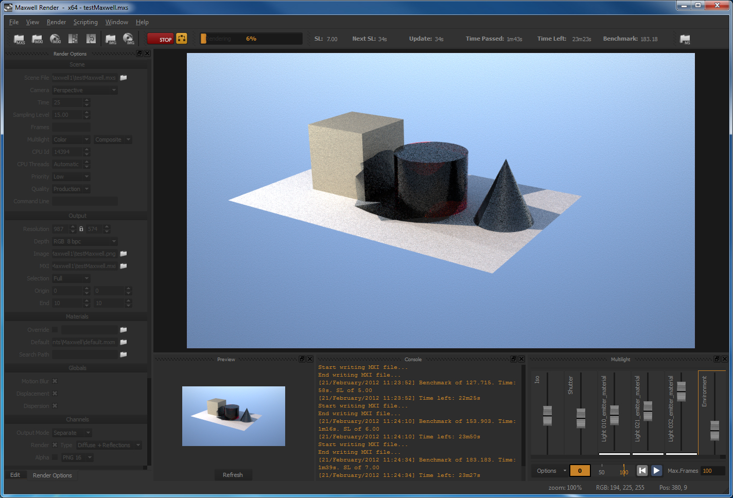
12. Stop "render" change to"camera" tab.
Adjust "resolution"
Re-render and adjust Iso and "shutter-speed"
13. Go to Multilight tab
Adjust lights as well as sun, etc.. while rendering
14. Go to Material Editor, and create emitter and call it
"myEmitter1"
Select wattage and other properties.
15. Go back to Rhino. Edit light properties. And assign emitter
to key spot lght via layer option or directly.
16. Note IES (Illuminating Engineering Society) options.
Used in defined emitter in Rhino plugin for Maxwell.
Lighting
Fixture Data and Examples
Additional notes
1. School of Architecture Maxwell wiki notes helpful to preparing this outline, written by Alex D'Aversa.
2. Rendering Farming Setup
with Maxwell (IT staff notes).