These notes describe two Grasshopper-Python graphics programs. The first one is based upon Serio's description of a an Occulus and the second one is based upon his description of an Oval. Some moderate use of Vector algrebra is used to replace methods that in Serio's time could have perhaps been constructed by string. The translation of Serlio's procedure made clear by Hart and Hicks [Hart, Hicks, 1998] is step by step parallel to the steps within the Python program program and is testament to the genius of Serlio's method . Within separate workshop notes we will explore recursion methods, such as used to developed a Koch curve, not so easily related to Serlio's linear logical of construction.
These examples also continue the rhinoscriptsyntax and the Rhino common libraries inside of Python.
For detailed references on the the libraries used in the examples below see:
Rhino
Common Libary - functions for Rhino Python, most of
which are alsoavailble to the Python scripting component within Grasshopper.
Rhino Script Syntax Library - functions for Rhino Python, most of
which are also availble to the Python scripting component within Grasshopper.
For published tutorials and manuals see:
Python
Scripting for Rhino and Grasshopper - overview
The
RhinoPython 101 manual. - step by step tutorials are at the end of pdf file
primer
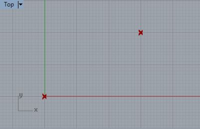
1. Construction of an Occulus Sequence
Within previous workshop notes we created a Python script to draw a rectangle. Similarly, this Occulus.gh Grasshopper and Python script begins with two corner points.
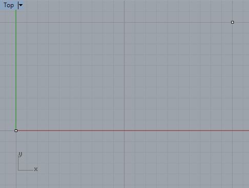
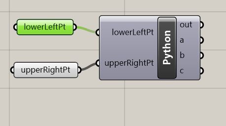
2. Each of the two corner points are in turn linked to a point
parameter components within Grasshopper, and the point
parameter components are re-labelled corresponding to the lower left
point and the upper right point in the Rhino drawing. Next, a Python
component is selected form the Grasshopper Math tab, and its input
parameters are also re-labelled to match those of the point parameter components.
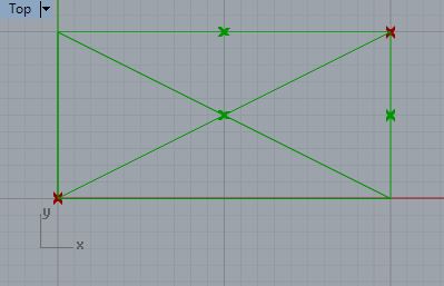
3. The consruction sequence is graphically as as follows:
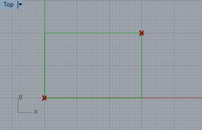
3.1 Complete the rectangle.
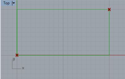
3.2 Determine midpoints of top and right side.

3.3 Add the major diagonal lines for the rectangle from corner to
corner.
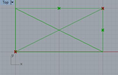
3.4 Find the intersection point between the major diagonal
lines.
3.5 Add a minor diagonal line from the lower right corner to the mid
point of the upper side of the rectangle.
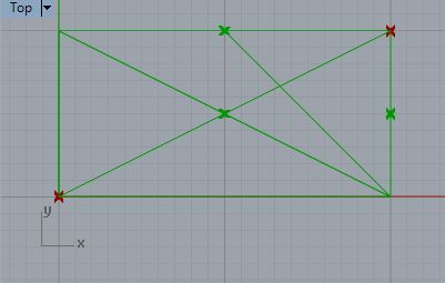
3.6 Find the intersection point between the major diagonal line from
the lower left corner and the minor diagonal line from the lower right
corner.
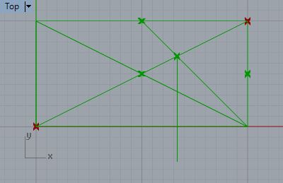
3.7 Drop a plumb line from the last intersection point down to the
ground (down the negative Y-axis direction in this case).
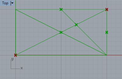
3.8 Draw a horizontal line beteen the intersection of the major
diagonal lines to the mid-point of the right side of the rectangle.
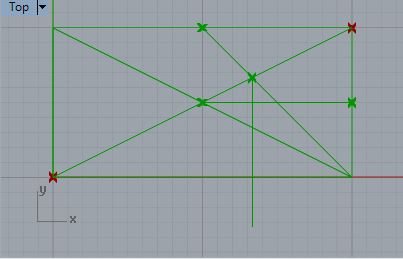
3.9 Find the intersection of the last horizontal line with the plumb
line.
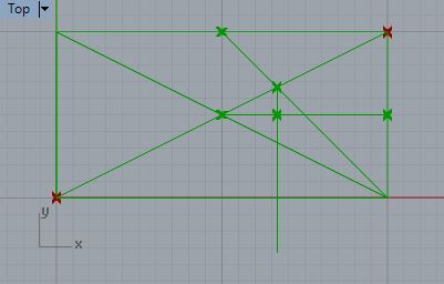
3.10 Determine the radius distance from the intersection point of the
major diagonals to the the plumb line intersect point to draw
the occulus inner circle.
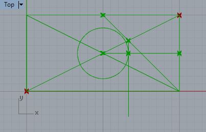
3.11 Add the outer circle of the occulus frame at roughly 10% greater
radius distance relative to the inner circle to signify the outer frame
of the circle.( This 10% radius increase isn't actually included in the
translation of Serio's method by Hart and Hicks, but is a visual guess.)
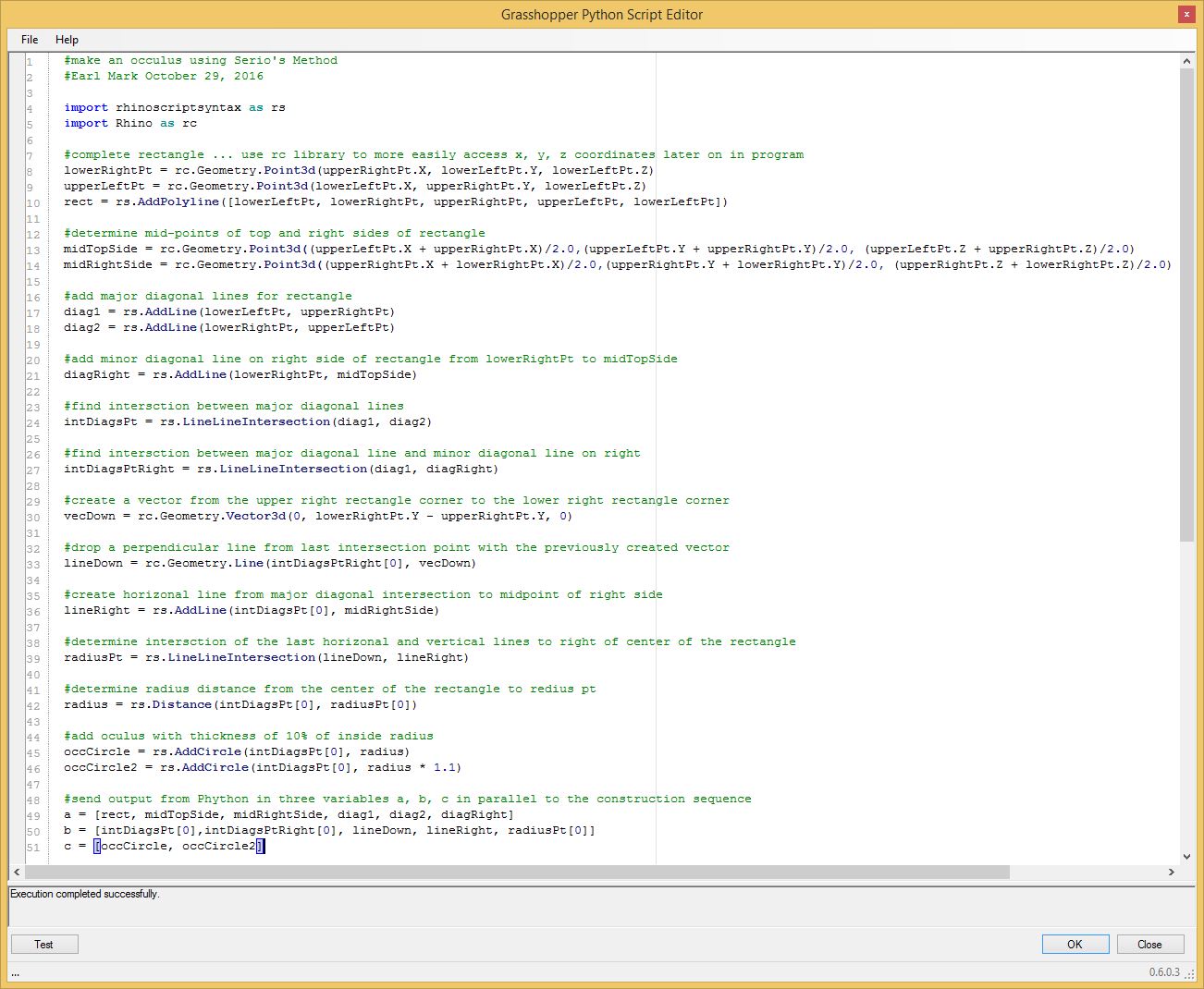
4. The steps of the procedure above are parallel to the
comment lines of the Python script itself below. Note that the vector
"vecDown" representing the plumb line is created by subtracting the
upper right corner of the rectangle from the lower left corner of the
rectangle in the script below. Three output variabes, a, b, and c, are
used to separate out graphic figures determined roughly by the "a"
beginning, 'b" middle, and "c" end of the script.
Note
that in line 10 below the point named "UpperLeftPt" is created
using a "rc.Geometry.Point3D" function the Rhino common library,
but in line 24 the point named "intsDiagRight" is created
using a "rs.LineLineIntersection" the rhinoscriptsyntax library.
There are indeed a number of similar and redundant functions created in
these two libraries; however, in the case of line 24, the function in
the rhinoscriptsyntax more directly provides the required result.
On the one hand, the "rc.Geometry.Point3D" function resuturns a single object, a Point3d, such as the point "lowerRightPt" in line 8 below. On the other hand, the "rs.LineLineIntersection" returns a list, such as the list "intDiagsPt" in line 24 below. The actual point3d itself is the first element of the list "intDiagsPt". Given that lists in Python use a zero based indexing method, we can get the first member of the list using the index value of "0", such as in the case of "intDiagsPt[0]" in line 36 below. A more detailed description of lists is beyond the scope of the present tutorial, but will be returned to in a later workshop. (For more details on the uses of lists in Python, see https://www.tutorialspoint.com/python/python_lists.htm. )
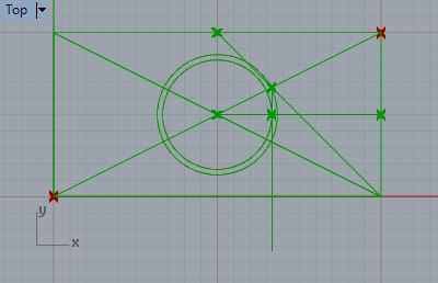
The key advantage to the computer based implementation of Serlio's
method is that the entire consruction of the Occulus is constrained by
the placement of the corner points of the original rectangle. Move one
of the corner points in Rhino and the occulus is automatically
regenerated at the appropriate proportion. For example, if the upper
right point of the original rectangle is moved closer to the lower left
point of the original rectangle, then the Occulus is automotically
reduced in proportion to the new rectantangle as depicted in the
following figure.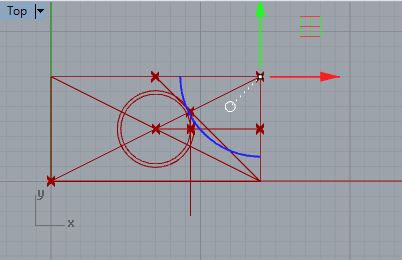
5. Construction of an Oval
The
development of an oval as also described by Serlio follows a smilar
sequence to that of an Occulus beginning with the original corner
points in the lower left and upper right corners. Similarly, the oval.gh
Grasshopper and Python script begins with two corner points.
6. Once again, each of the two corner points are in turn linked to a point
parameter components within Grasshopper, and the point
parameter components are re-labelled corresponding to the lower left
point and the upper right point in the Rhino drawing. Next, a Python
component is selected form the Grasshopper Math tab, and its input
parameters are also re-labelled to match those of the two point parameter components.
7. The consruction sequence is graphically as as follows:
7.1 Complete the rectangle.
7.2 Determine the midpoints all the sides.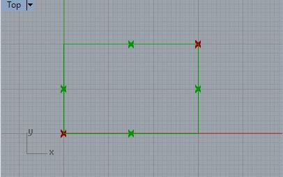
7.3 Add minor diagonal lines for left and right halves of the rectangle.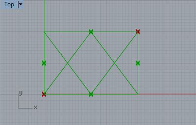
7.4 Determine left arc center point and right arc center point at intersections of diagonal lines.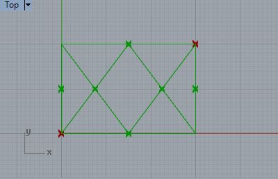
7.5 Get the vector from the center point of the lower side to the center point of the upper side of the rectangle.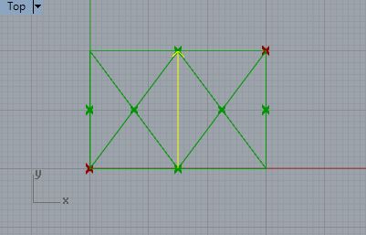
7.6 Convert the vector to a unit vector (a vector of length 1).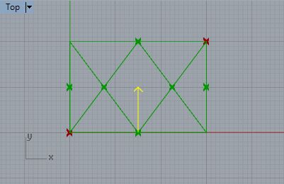
7.7
Multiple the unit vector by the radius length (the length of the line
from the mid point of the bottom side to the upper right corner). The
end of the vector will be used to determine the midpoint of the upper
oval arc.
7.8 Similary get the vectors for the right, left, and bottom arcs.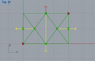
7.9 Determine the points at the ends of the vectors.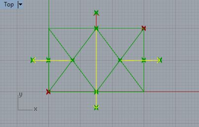
7.10
At the bottom of the rectangle, draw an arc counter-clockwise from the
lower left point of the rectangle, to the arc midpoint, to the lower
right point of the rectangle.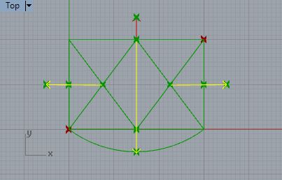
7.11
Similarly, in the counter-clockwise direction, draw the right arc of
the oval starting with the lower right point of the rectangle.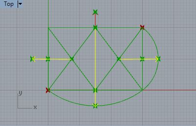
7.12 Complete the remaining arcs in the same counter clockwise manner.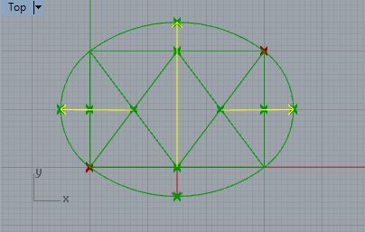
If
each over arc was to be constructed manually with a string, steps
7.5 through 7.7 would be supplanted for the top arc, and similary for
all the other arcs. That is, in the case of 7.5 through 7.7, the
vector based approach is similar to putting one end of a string at the
midpoint of the bottom side of rhe rectangle and the other end of the
sting at the on the upper right corner point of the rectangle, and then
rotating out an arc from the upper right point to the upper left point
of the rectangle. Although the ovall logic of the process is indepted
to Serlio, here we have used a vector algebra to make arcs easier
to re-compute if we want to adjust the the size of the original
rectangle by moving either of its original two corner points (see
figures 8.1 and 8.2 below).
8. Note that completed oval is now constrained by the original corner points similar to the example of the occulus.
8.1. Here is the oval without the radius vectors displayed.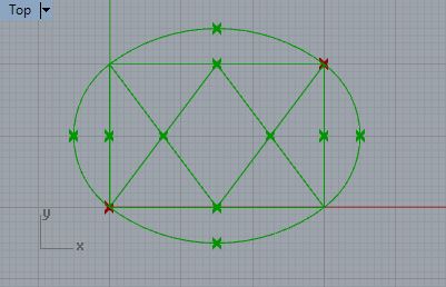
8.2
In the next figure the upper right hand corner point of the original
rectangle has been moved and the oval has been automatically resized
accordingly.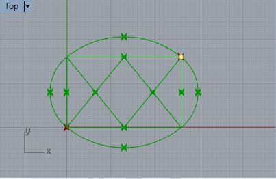
9. The steps of Serlio's procedure above are parallel in the
comment lines of the Python script itself below. Three output variabes, a, b, and c, are
used to separate out graphic figures determined roughly by the "a"
beginning, 'b" middle, and "c" end of the script.
Note
that, similar to steps 7.5 through 7.8 above, in order to find the
center point of any of the oval's arcs, it is necessary to do a vector
algebra in four steps (lines 34 to 48 in the script below):
Step 1.
Get the vector from the center point of the arc to the mid point
of the rectangle side that is adjacent to the arc.
Step 2. Get the unit vector (a vector of length 1) from the vector of Step 1.
Step 3. Multiply the unit vector by the lenght of the radius of the arc.
Step 4. Add the vector from step 3 to the center point of the arc to find the center point of the oval's arc.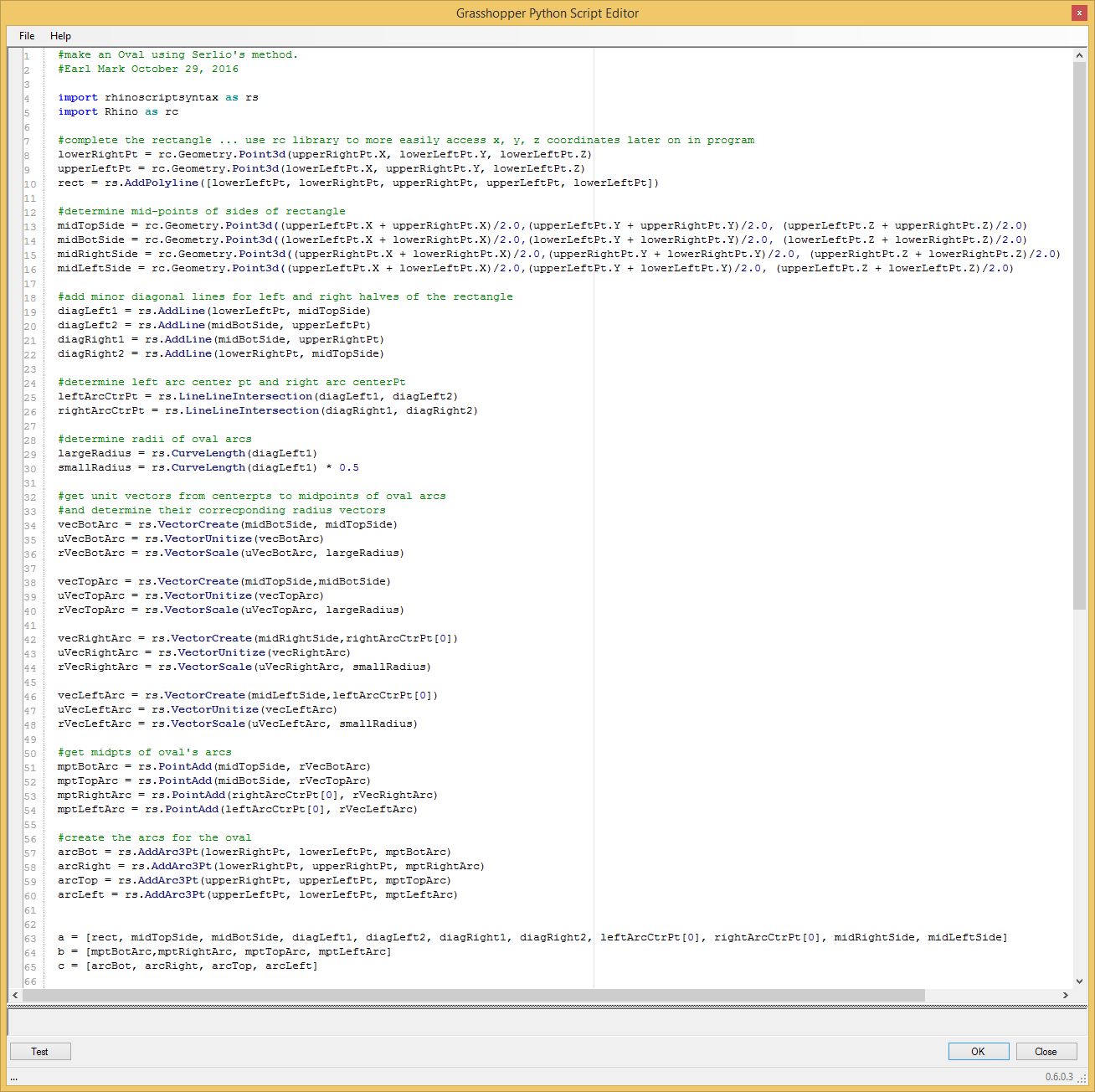
Reference
1. Hart, Vaughan; Hicks, Peter, eds. (1996), Sebastiano Serlio on Architecture Volume One: Books I-V of 'Tutte L'Opere D'Architettura et Prospetiva', New Haven & London: Yale University Press