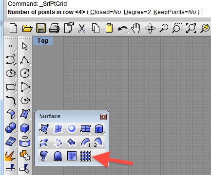
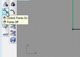
- Select the tool to create planar Surface from four rows of four points from the surfaces palette
COMPUTER
AIDED
ARCHITECTURAL DESIGN
Workshop 5 notes,
week of September 20, 2016
Projection With Surface and Solid Editing, plus Delaunay Mesh and Height Field Digital Terrain Modeling
PART I: SURFACE EDITING
1. Surface Generation with Control Points
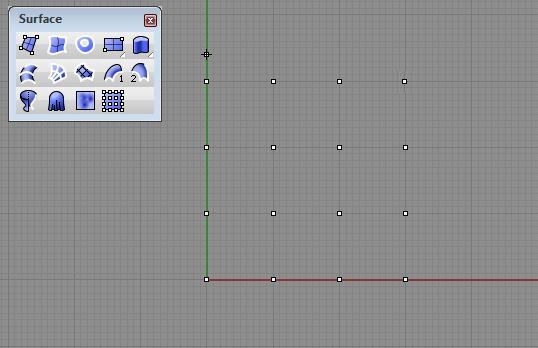
- Select the tool to create planar Surface from four rows of four
points from the
surfaces palette

- create the grid of four by four points and the surface is generated
 |
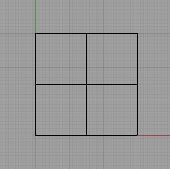 |
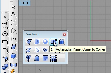
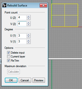
- alternatively, create a planar surface by two corner points, and use the command line "rebuild surface" to rengenerate the surface with 4 x 4 control points:
 |
 |
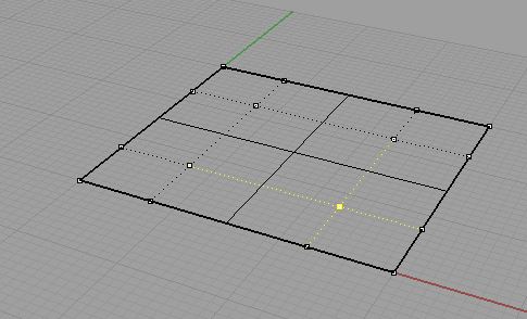
- Choose the control-points on tool and select the surface.
With the "ctrl" key selected ("ctrl" & "shift" key on an Apple keyboard), select and elevate points to make wavy surface.
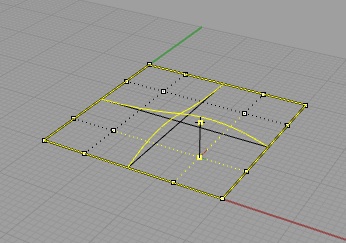
before after
- view the surface with simple shading directly in the viewport
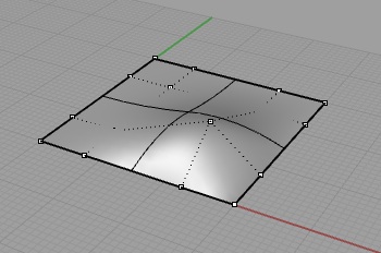
- turn off the display of the control points, change the active layer and color -> draw a closed polyline shape on top of the planar surface
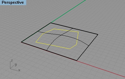
- change the active layer and color -> draw a circle on top of
the
planar surface
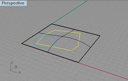
- change the active layer and color color -> draw a bSpline on top of the planar surface
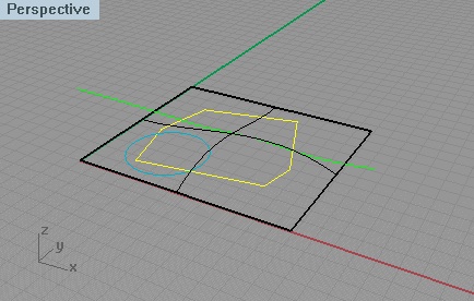
- grab all three elements and use the Move tool to reposition them to hover above the surface.
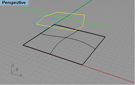
- In the "top" view, grab all the entitites- and use the Copy command to make three Copies to the side
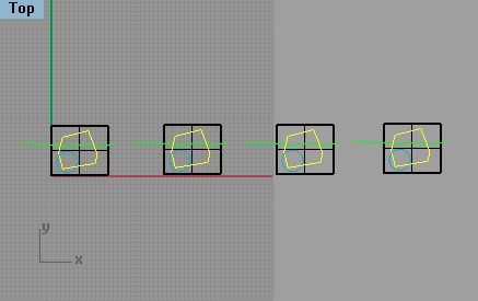
- Zoom
to first surface
- Select Trim surface tool
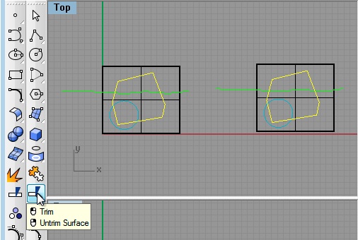
- Select
the polygon, enter the "return" key (or
right-mouse click), select the surface area corresponding to inside the
boundary of the polygon, and the enter the "return key"
- Note where grabbing surface -
internal or external to projection is portion deleted
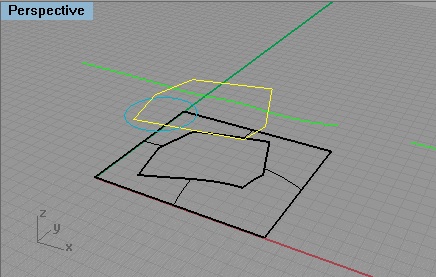
- Do the same command again with Circle
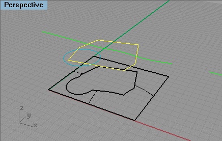
- Do the
same command again with bSpline
- note again which side you grab on surface matters to what is retained.
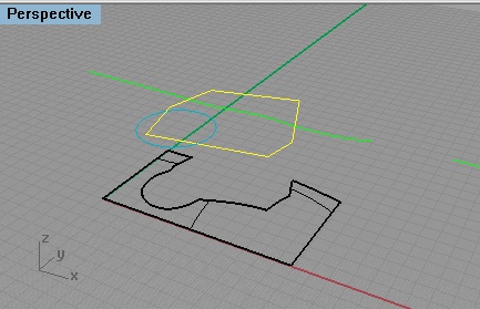
2. Now
revisit the the same geometry, but this time, split, rather than trim
the surfaces with the "split surface too".
- Change settings to Split Surface - test for polygon, circle and
bpsline.
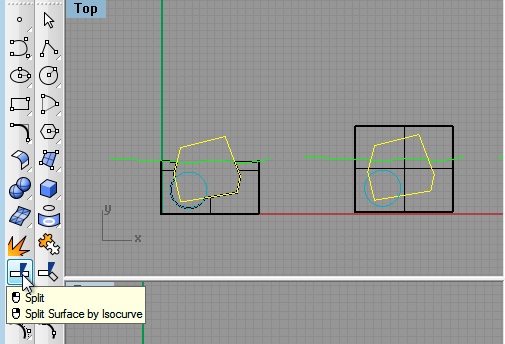
- similar to before, select the surface to split, enter the "return"
key (or right-mouse click), select the polygon to perform the split,
and enter the "return" key (or right-mouse click)
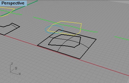
- similarly, use the circle to split both surfaces by first selecting the two surfaces, enter the "return" key (or right-mouse click), select the circle to perform the split, and enter the "return" key (or right-mouse click)
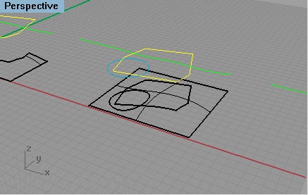
- simlarly, use the bspline to split the two new surfaces below it
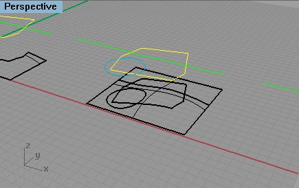
3. Change to Method to Project Curve - repeat the command on the above three elements
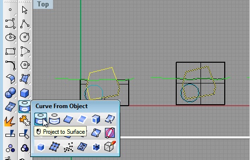
- on the 3rd copy of the original entities, select the polygon, circle, and bspline, enter the "return" key (or right-mouse click), and then select the surface below

4. Now, we will apply the trim surfaces tool to split a surface with another surface.
- on the fourth copy of the original surface, rotate a copy surface upon itself fron the "front" view
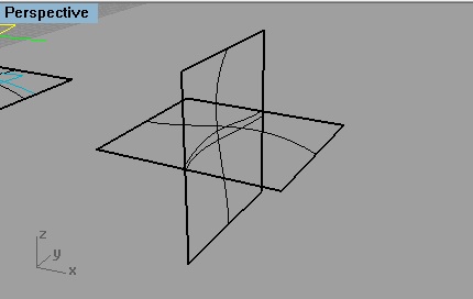
- Use Trim Surfaces tool from before, select the rotated surface first,
enter the "return" key (or right-mouse click), and then select portion
of the surface below to be trimmed away second.
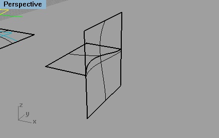
- Similarly, use the trimmed horizontal surface to trim the lower portion of the rotated surface.
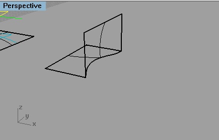
5. The mesh tool converts a bspline surface into a faceted polygon surface.
- Go back to the third copy of the original surface, polyline, circle and bspline, and erase the projected elements.
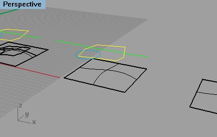
- Select the Mesh from Surface/Polysurface tool
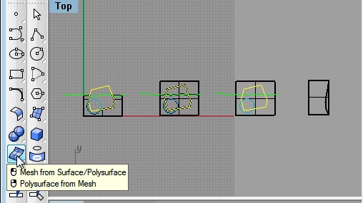
- Select the surface on the ground, and in the dialog box that follows, choose the default middle number of polygons, and enter "OK"
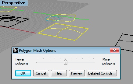
- A polygon mesh is now superimposed on the original surface.
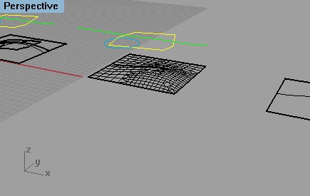
- Turn on the control points, and move individual points on the mesh as was done with the original surface at the beginning of the workshop
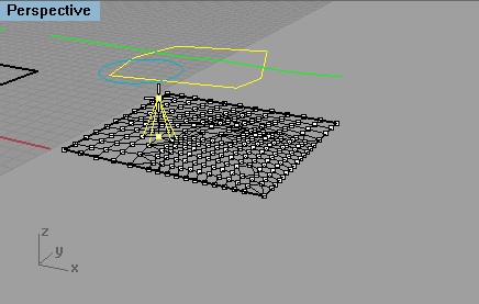
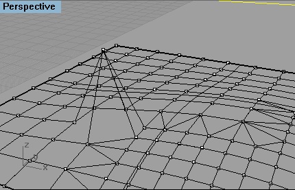
- Note that the result is faceted rather than smooth as in the case of the original pre-meshed surface
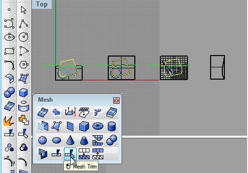
- Turn off the control points on the mesh. Note that the command MeshTrim and MeshSplit tools can be used to trim to the mesh surface.
 |
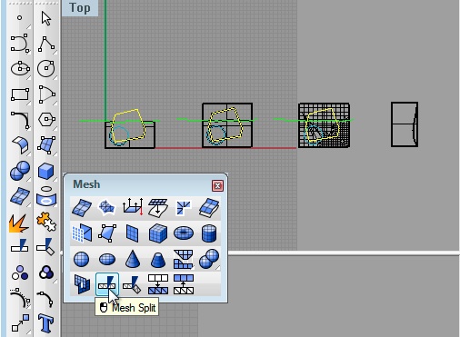 |
- For example, as was the case with the original surface, select the "Mest Trim" tool, select the polygon, enter the "return" key (or right-mouse click), and then select portion of the mesh below to be trimmed away
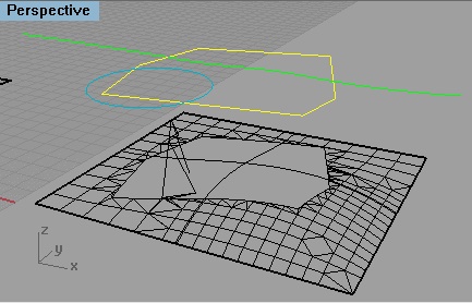
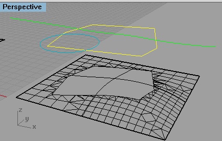
Note that a portion of the original mesh was modified by moving a control point earlier. This portion of the mesh may need to be trimmed separately. Compare the image below where the "Mesh Trim" tool was reapplied a second time with the image immediately above where the "Mesh Trim" tool was first applied. Several facets towards the left-hand corner of the hole are remove in this second pass.
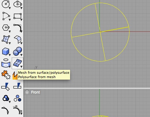
6. Apply mesh tool on simple solid sphere.
 |
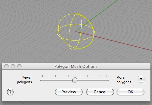 |
- Yields meshed sphere.
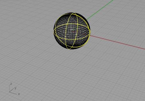
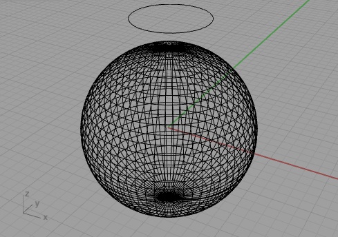
- Go back to MeshTrim tool- perform with a circle on the meshed surface. Similar trim results as before.
 |
 |
5. Reverse Method
- Remake the wavy surface with three cutting entities.
- Perform the trim surface command for all three entities.
- Select the Untrim surface tool, selected the trimmed edge of the surface, and the surface will be restored.
- Create a planar surface oriented perpendicular to the existing surface. Use the trim tool to cut the surface.
- Once again, select the Untrim surface tool, selected the trimmed edge of the surface, and the surface will be restored.
- Copy the vertical surface five times along the y axis, select the split tool, select the the horizontal wavy surface, enter the right-mouse button or the "return" key, then select the vertical surfaces, and enter the right-mouse button or the "return" key, and the ground surface is split into six surfaces. Note that there is no reverse option other than the undo tool.
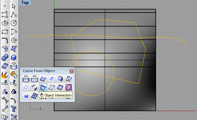
7. Object intersection.
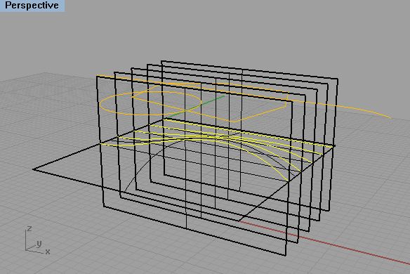
- For the same set of surfaces, select the object intersection tool, and then the horizontal surface and all the vertical surfaces, and the intersection curves are generated.
 |
 |
7. Linear Slices
-
Reduce the drawing downabove to the
original wavy surface.
- Go to the Top View orientation
- Draw a line over and bypassing the surface.
- Copy the line five times at equal
intervals so as to determine six total such lines..
- Now using the project curve tool, select the select the horizontal
lines and enter the right-mouse button or the
"return" key, then select horizontal
wavy
surface, and five section lines are created.
- and the ground surface is split into six sections:.
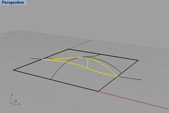
Triming surfaces can also be done with planar, non-planar and
non-linear elements.
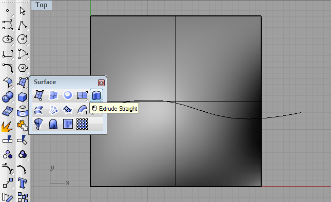
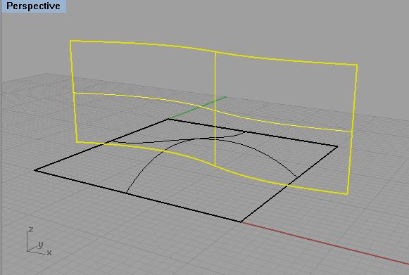
- draw a bspline at curving across the ground plane and then
extrude bsline
to get a singly curved upright plane.
 |
 |
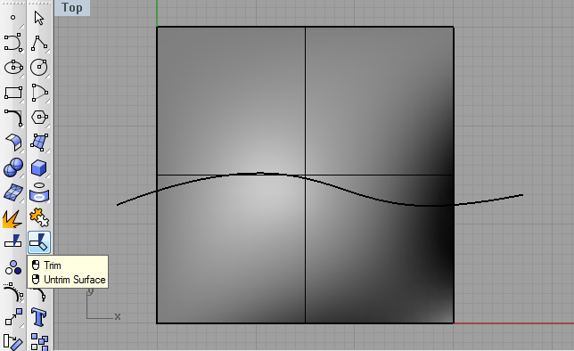
-Use the trim suface tool, select the horizontal wavy surface, enter the right-mouse button or the "return" key, then select the extruded surface, enter the right-mouse button or the "return" key, and get a continuous vertical surface section:
 |
 |
8. Slicing a solid with a surface.
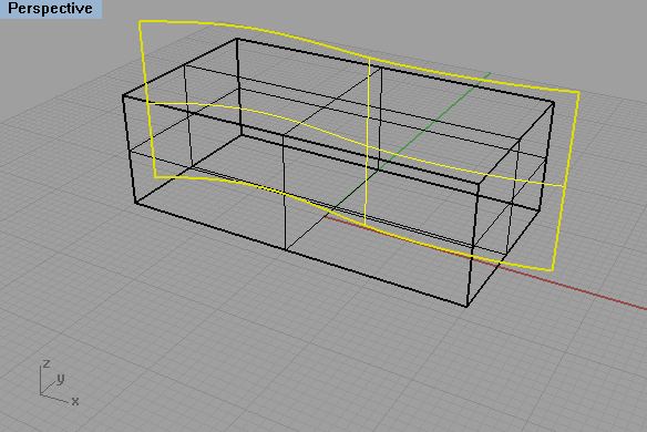
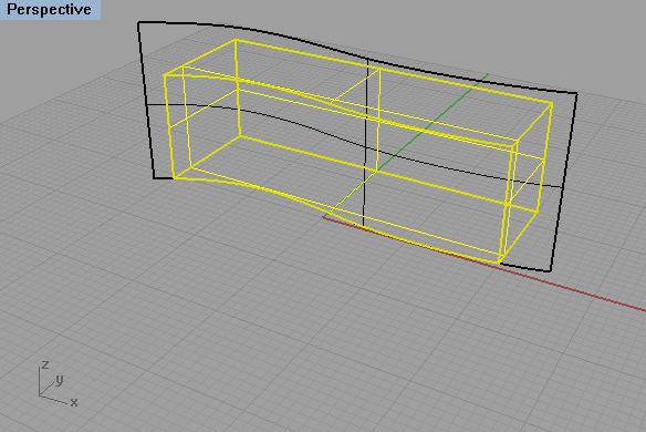
The same trim command can be used to slice a solid with a surface.
- Create a solid box, and extrude a bspline curve through the box.
- Select the trim surface tool, select the extruded bspline, enter the right-mouse button or the "return" key, then select the portion of the solid box to remove, ,enter the right-mouse button or the "return" key, and you get a sectional slice of the box.s
 |
 |
9. Cutting a solid with a doubly curved surface.
1 In the Solids Modeling tools, create a solid box.
- Using the "Set CPlane by 3 Points" construction plane tool, determine a construction plane on the front face of the cube
- Using the "mid" snap, draw a bspline on the front face of the box from the mid-point of one corner to the mid-point of the opposite corner.
- Similarly, draw bsplines on the other three faces of the solid, end-to-end with the first bspline.
- Now, using the "Surface from Edge Curves" tool, select the four splines and generate a doubly curved surface.
- One again, using the trim surface tool, use the doubly curved surface to trim off the upper portion of the solid box.
PART II: DELAUNAY MESH
1. Generating the mesh.
The Delaunay Mesh tool is a Rhino plugin that provides you with a method to triangulate a mesh from contours or spot elevations.
It is loaded on all public and classroom computers within the School of Architecture and can be lauched by typing in "Delaunay" at the Rhino command promp.
Here is some more information about how to acquire your own copy the plugin which is taken from directions provided on the School's IT web site. For your own laptop running Rhino, you can find this plugin in the Projects drive under:Projects\Resources\plugins\Rhino\PointSetReconstructionTools.
Drag the two files in there to the plugins folder on your computer:
C:\Program Files\Rhinoceros 5.0 (64-bit)\Plug-ins
or
C:\Program Files\Rhinoceros 5.0\Plug-ins
Then open Rhino, go to Tools > Options Find Plugins in the list on the left, and click the Install button. Navigate to your Rhino plugins folder (C:\Program Files...), find the PointSet Reconstruction Tools plugin, and load. Close the Options and you're ready to go.
For working with the files illustrated below, go to the the CLASSES server and copy the folder: Classes\Arch2710-6710-Mark FAL2016\Examples\DTM onto your desktop.
From within the folder open the file carrsHill.3dm inside Rhino. From the layers panel, make a new layer "TIN", set it as the active layer, and give it a light green color (actually, this has already been done for you inside the file).
Type the command "Delaunay" into Rhino. (This command is part of the
Pointset Reconstruction Tools plugin - see below for where to get the
plugin).
When prompted, select the contours (or other geometry) that you want the mesh to be made from. That is, drag a a rubber-banded selection fence around all the contours:
Hit Enter when all are selected.
Next, the command will prompt you for a sample interval number.
Use the default
setting of 1.0.
Use the enter key and a preliminary mesh will be generated. Next To just get a simple surface (no analytic shading), turn the Shader to none, and then hit Complete.
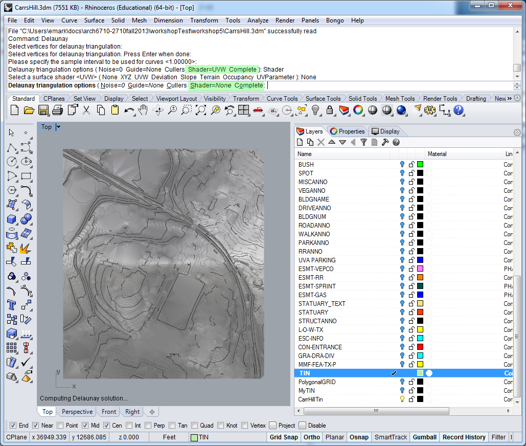
You now have a triangulated
surface mesh from your contours. View it in perspective and shade it.
For more details on this method, to get the PointsetReconstuction plugin, see
To get a simpler mesh representation, change back to the top view. In the layers dialog box, change the active layer to the one named "PolygonalGrid" and adjust its color to an olive green. Turn off the layers named "INTERMED" and "INDEX" to remove the contour lines from the view.
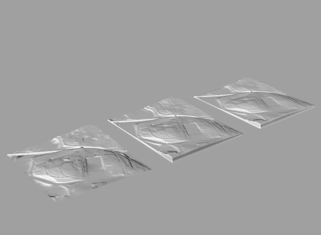
Next, from the create surfaces palette select the drape mesh tool and, using the default spacing of 5 units, drag a rubber-banded selection fence around the Delaunay mesh.
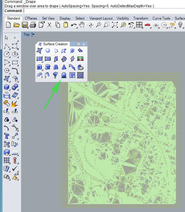 :
:
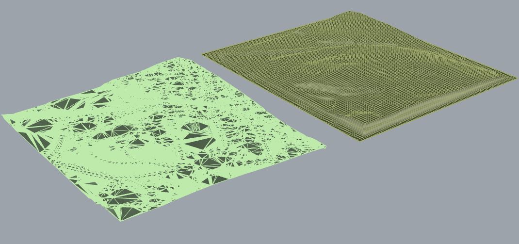
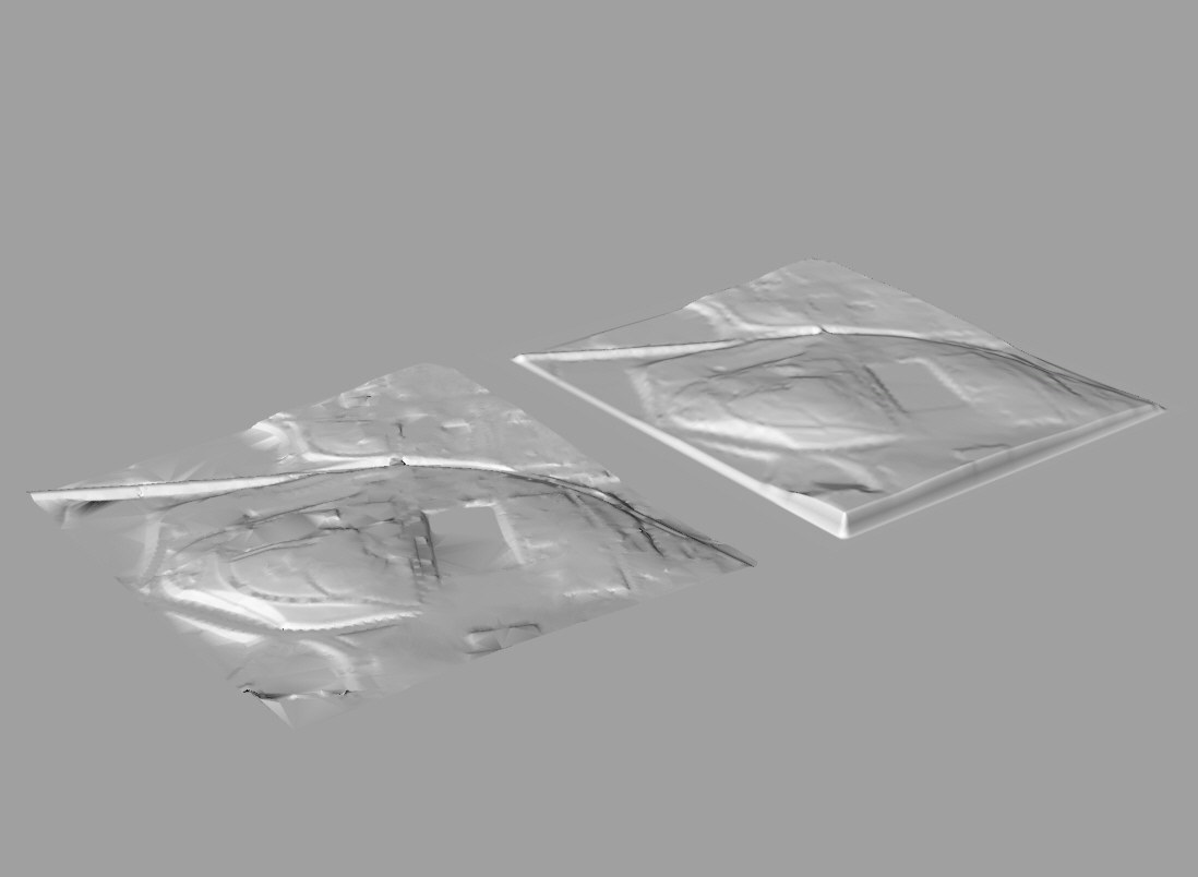
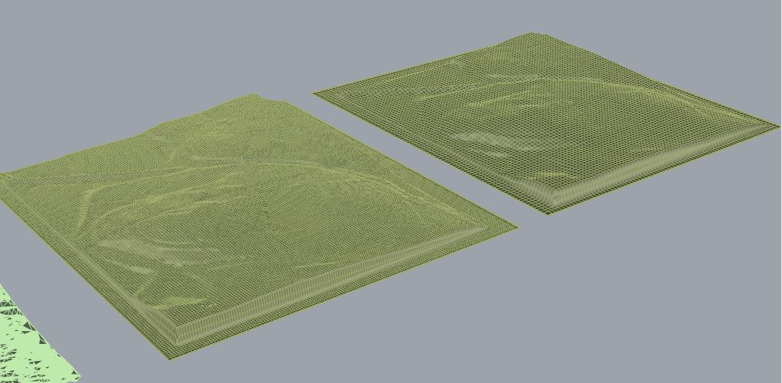
2. Converting a pixel map into a 3D mesh.
Note that this example is based upon a gray scale bit map of the Grand Canyon (see http://www.opentopography.org/index.php/news/detail). The area is approximately 270 miles long. The depth of the Canyon is roughly 1 miles +/-. For simplicity at the approximate scale of 1 ft = 2 mile, the image bit map is scaled along the x-axis in Rhino at 270 feet. To be more easily detected, the depth of the resulting terrain mesh within Rhino is created 3 times its true relative scale. The entire terrain could be more easily represented at full scale using an alternative approach that will be described later in the semester.
2.1 Building the "height field".
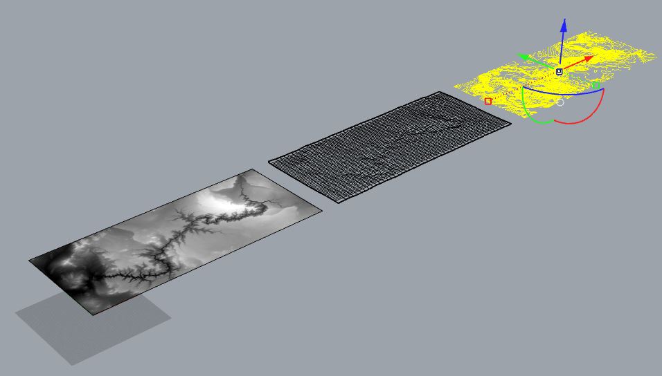
Initiate a new Rhino Drawing and maximize the "Top" view.. At the command prompt type in "PictureFrame", and from the DTM folder, select the file, "Grand_Canyon.png". When prompted for the " First corner of the picture frame", type "0,0", and when prompted for the "Length of the picture frame, type "270,0". Next do a "Zoom extents". The top view should appear as follows:
Next, create a layer such "terrain", and make it the active layer. Open the "Surface Creation" palette, select the "Heightfield from image" tool.
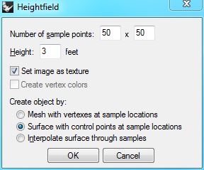
Choose once again the same file "Grand_Canyon.png", and when prompted for the " First Corner0,0", type "0,0", and when prompted for the "Second corner or length", use the object snap "End" filter, and snap the mouse to th lower right-hand corner of the picture frame at the location "270,0". In the "HeightField" dialog box that follows, set the "Number of Sample Points" to 50 x 50, set the "Height" to 3, check-on the option to "Set image as texture", and the option to "Surface with control points at same locations" as follows:
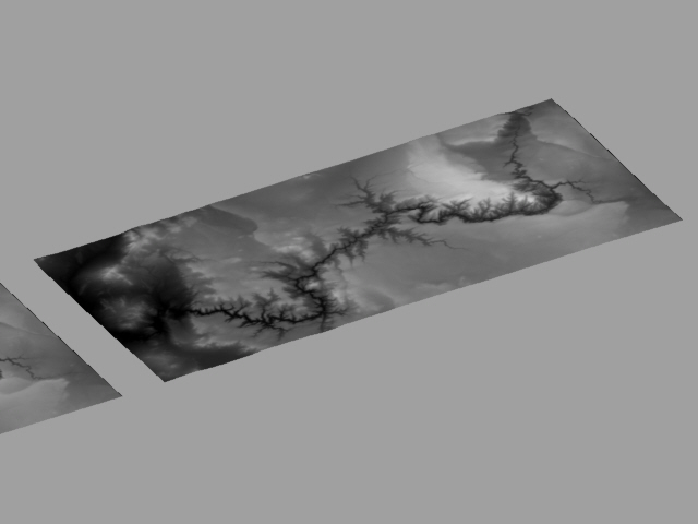
When viewed in wireframe in the Perspective view, the height field mesh should appear as follows:
2.2 Re-contouring the mesh.
Use the "view extents" tool so that the full height field is visible. WIth the "Ortho" lock on, move the height field to the right of the original picture frame such that the perspective view now appears as follows.
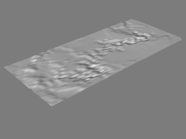
Use Rhino Render to view the "height field" with the original Grand Canyon image applied texture map.
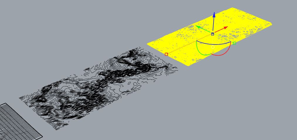
Display all four view windows simultaneously, and from "curve from object" palette, select the "Contour" tool.
Next, from the Right view,select the height field mesh, press the
enter key, and when prompted "Contour plane base point" enter the value
0,0 and press the enter key. When prompted "DIrection perpendicular to
contour planes", enter the value "0,3" and press the enter key. Whe
prompted for "Distance between contours" enter the value 0.1 and press
the enter key. When prompted for the "Contour plane base point", enter
a data point at the origin by typing "0,0,0", and when prompted for
"Direction perpendicular to contour planes" turn on the "Ortho"
button at the bottom of the Rhino Window, and using the left-button on
the mouse enter a data point directly above it.
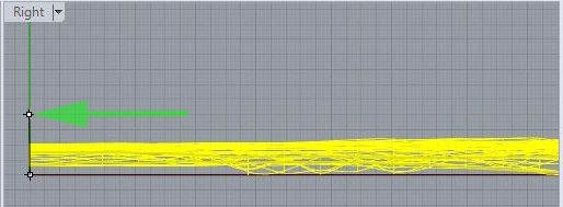
Now, move the contours to the right of the hight field mesh in the ground plane.
