COMPUTER
AIDED
ARCHITECTURAL DESIGN
Workshop 10
Notes,
Week of October 30, 2017
TEXTURE MAPPING, REAL SCALE AND ADDITIONAL MATERIAL PROPERTIES
These workshop notes cover cover different kinds of material mapping techniques and control of scale for V-Ray plugin to Rhino.
VRay Mapping Techniques
1. Create The Rhino File and Get Some Images of Materials
Create a working folder in your desktop. Open Rhino, create a new Rhino 3dm file in working units of "feet" and save it to to the same folder. Copy the folder from the Classes server "CLASSES\ARCH2710-6710-Mark-FAL2017\examples\materials" to the desktop folder where you have saved the 3dm file.
2. Create three objects sit7ing on a surface in the ground plane as in Workshop 6with two spot-lights and a point source light as was created for workshop 6.
3. Set V Ray as the rendering plugin by going to the menu item Render>Current Renderer > V-Ray for Rhino

4. To create a brick texture map, go to the menu item V-Ray Asset Editor
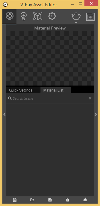
Within the V-Ray/Material Editor, create a "generic" material named "my_brick" per the methods workshop 6. Within the expanded Material Editor, select the checker box icon editor adjacent to the "Color" specifcation area adjacent to the "Diffuse" tab.

Next, select the "Bitmap" option on the left.
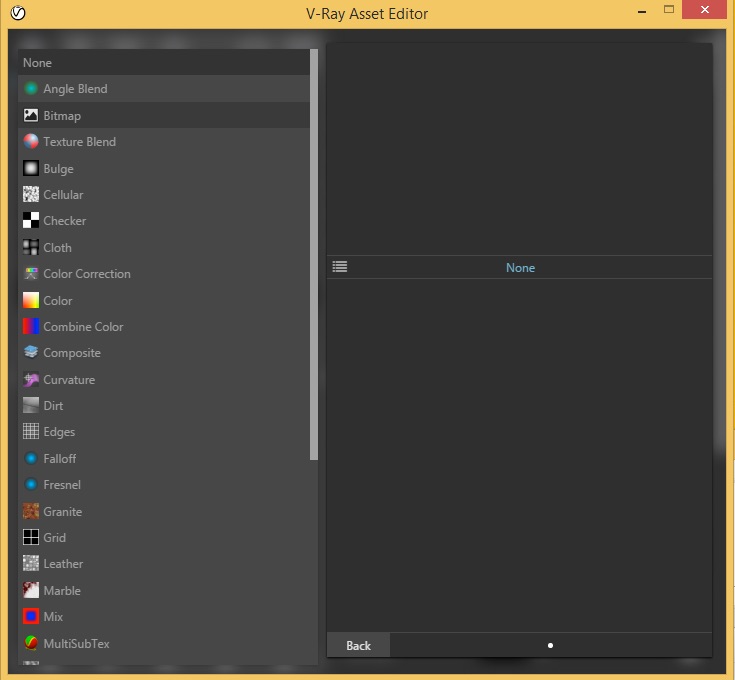
Next, select the file "jamesstchapelbrick.jpg" from the materials folder created previously.
Now preview the brick within the V-Ray material editor.
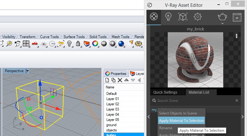
Select the block within the pespective view in rhino, right-click on "my-brick" and select the option"Apply Material to Selection"
Now go to the properties editor for the block, and select the "Apply Box Mapping" tool.
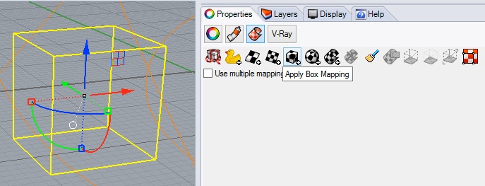
Within Rhino, select opposite corner points on the ground, and an upper corner point to determine the scale of the box mapping.
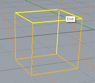
At the command prompt select "Yes" for capped.
Now, back with the properties editor, note the XYZ size at 1.000, 0.9000 and 1.000 in the case here, which is in the model dimension units of feet of the box in the x, y, and z directions.
Render the box for a mapping at this scale, and note the entire texture map is scaled to the exact size of the cube, such that the scale of the bricks varies accordingly in each face of the cube.
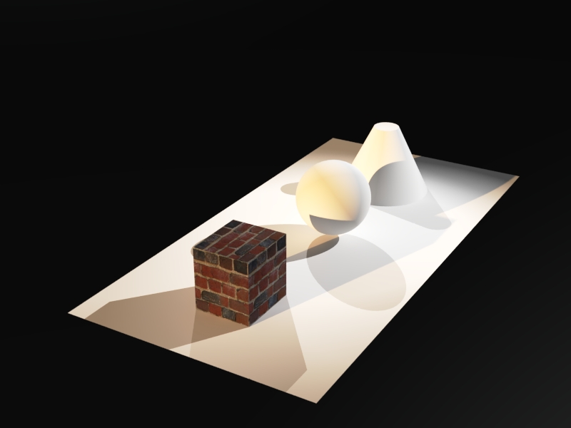
However, witin the properties editor, adjust XYZ size by entering values of 1.0, 1.0, and 1.0. This establishes that the scale of the brick texture is 1 unit (1 foot) each along each directlion.
Re-render the cube and the result (which here looks the same as the prior rendering) has been adjusted to 1 x 1 x 1 scale or just 10 % more in the Y direction..
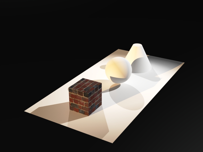
Note: If the mapping scale doesn't change, you may need to select the cube and use the "Delete Mapping" tool option. There is an occasional problem with V-Ray that may prevent the re-scaling to occur immediately. In this case 1_ use the "Delete Mapping" tool shown below, 2_reinitiate the apply box mapping option described above, and 3_reset the X, Y, Z size as also described above, and then re-render.
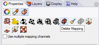
The "Delete Mapping" option may be necessary between each of the changes below on a a case by case basis.
To adjust the texture map in a tile pattern along each
face of the cube, Change the UVW repeat
parameters to 2, 2, 2 to double the texture map.
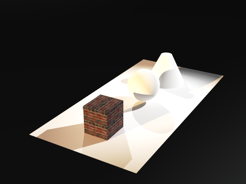
2. Or, change the XYZ size to 0.5, 0.5, 0.5 with the UVW size at 1.0, 1.0, 1.0 for a simlar result. That is, tile of the map is at the scale of 0.5 units (i.e., 0.5 ft.) each.
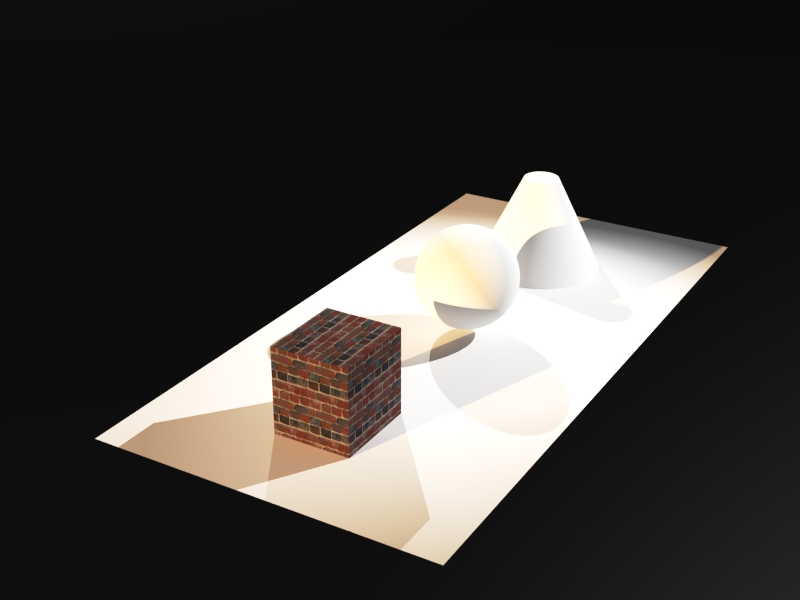
5. To create a slighlty aged look, go back to the V-Ray Material Editor, select the "Maps" tab, and the "Bump" options, and then select "mybrick" for the bump similar to the method above in selecting "mybrick" for the diffuse color:
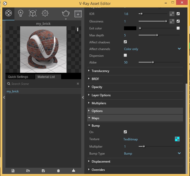
Render the brick to see the rougher texture based upon the light and dark values of the original brick image:
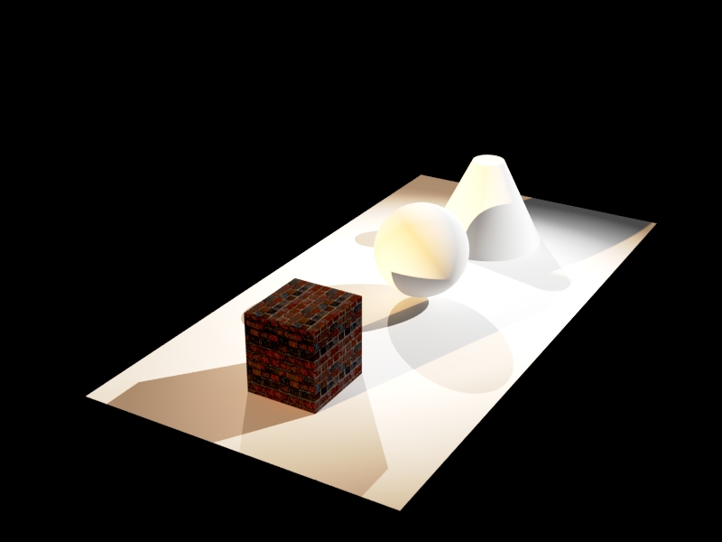
Note that in the image above that the lighter values (grouting) are translated to hills and darker values (clay brick) are translated to valleys in the interpretation of the bump map. To reverse the meaning of the bump map, change the multiplier to -1.5.
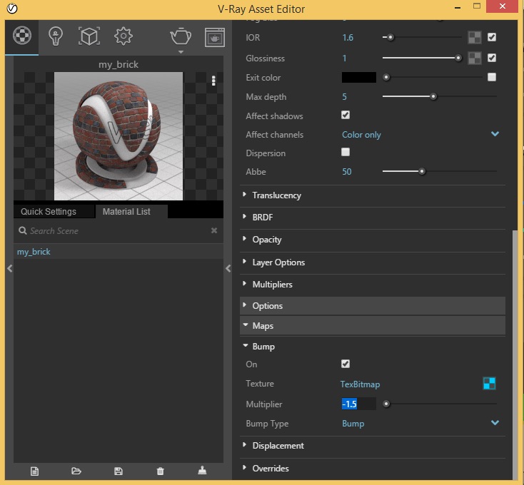
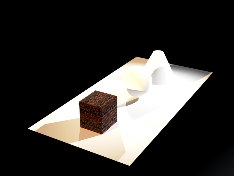
Render the same view and note that the grounding appears below the bricks in the surface on the cube, but given that the "bump" map is superficial, it's the effect of reversing the values is not all that noticeable if at all::
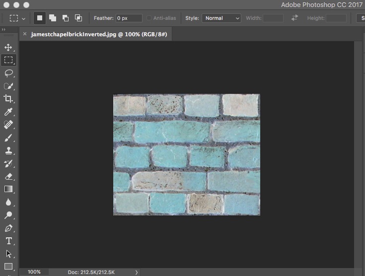
Alternatively, in Photoshop select the original brick image and use the menu "Image/Adjustments/Invert" to make the grouting appear darker than the bricks.
Select off the "bump" map and turn on the "displacement" map for the brick. Following a similar procedure to the bump map set the mutiplier to 0.05.
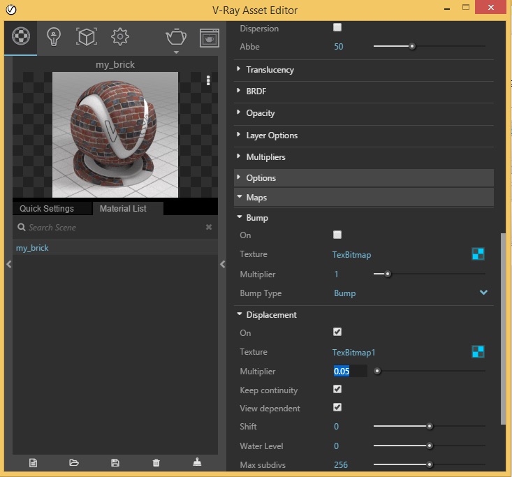
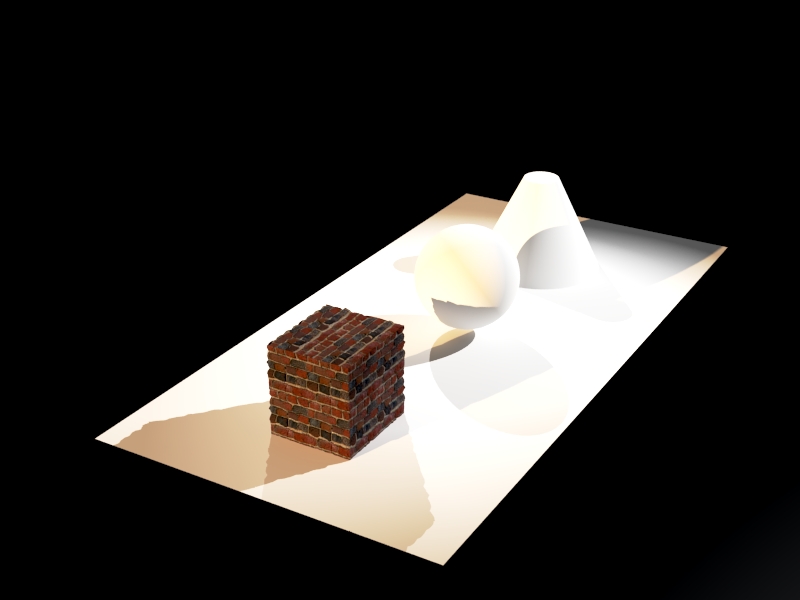
Next,render the brick and note the subtle reverse of the brick texture map where the grouting appears to be receding:
Alternatively, for a simpler weathered look, in the material editor, turn off the displacement map, turn back on the bump map, select the checker box icon, and use the "Noise" map rather than the literal brick photo, and with the multplier for "Color A" set to 0.2, the mutiplier for "Color B" set to 0.2 and the frequency set to 22:
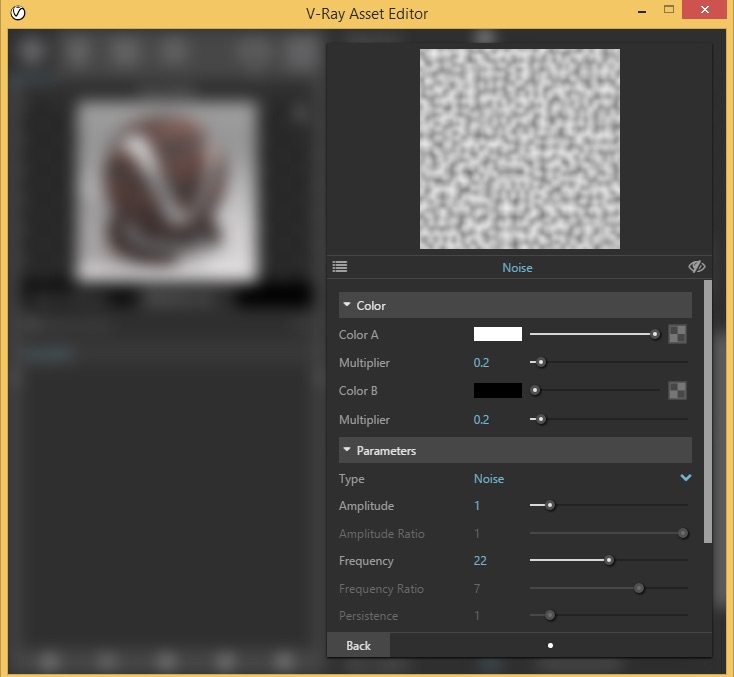
The resulting sample brick will appear as follows:
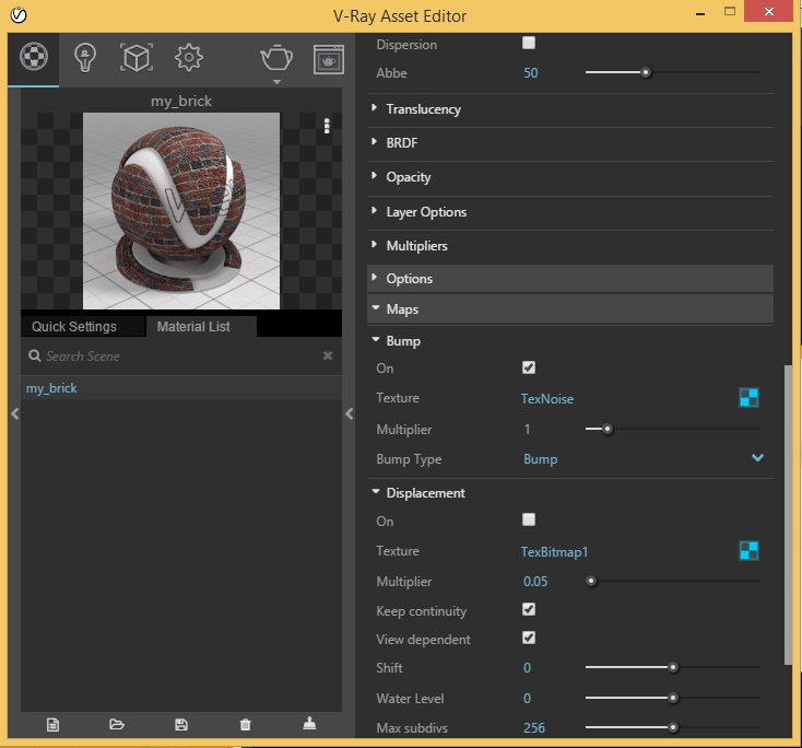
The rendering of the brick cube then appears as follows:
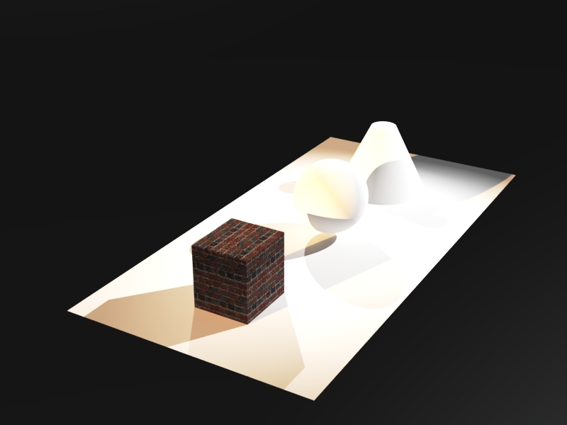
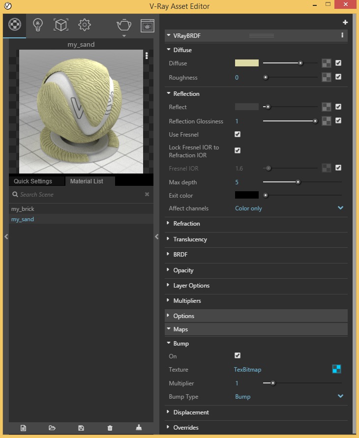
6. To add a bump map on the ground, go to the V-Ray Material Editor", create a material "my_Sand', go to the Maps tab, and select the checker-box adjacent to the word "Bump" and, following a similar procedure to step 5, choose the sand image for bump map.
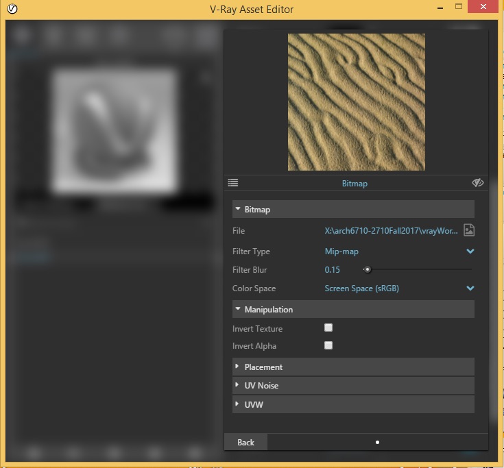
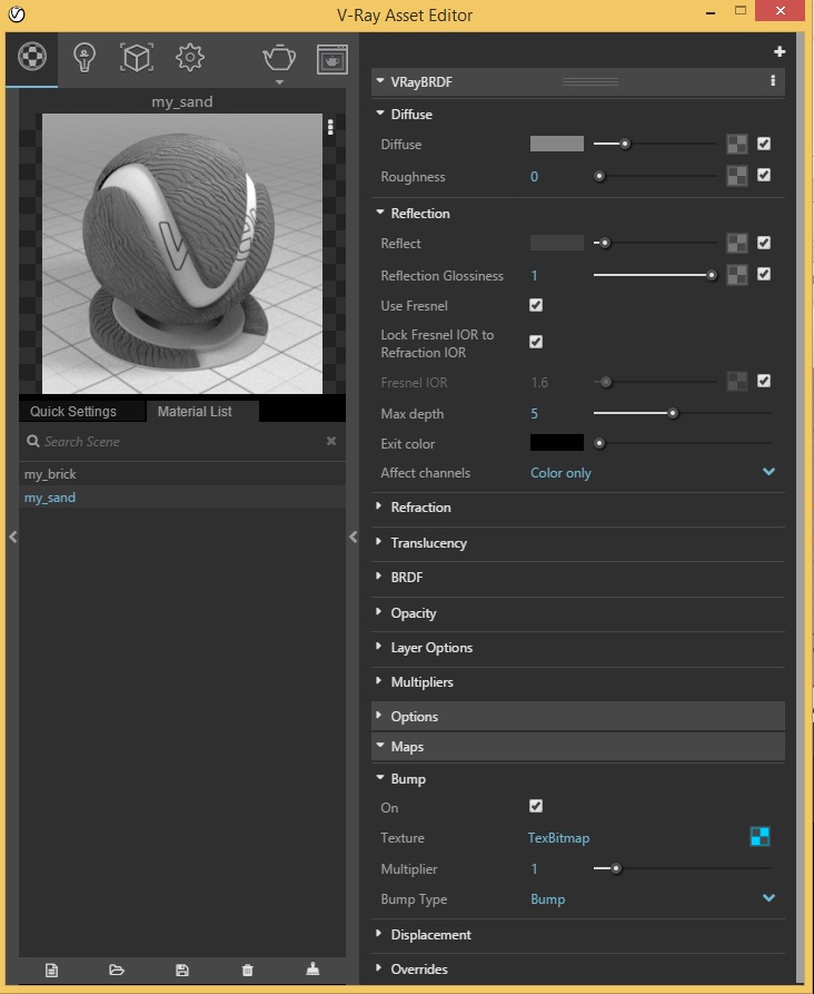
Next, after selecting the "back" button, and back in the material editor, set the diffuse color slider to a mid level gray, and also drag the reflection slider from black to dark gray:
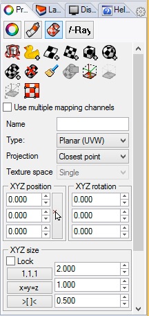
Select the ground plane, and go to the properties attribute and then the texture mapping tool, and select "Planar Mapping" icon and trace the corners off the ground plane highlighed below.
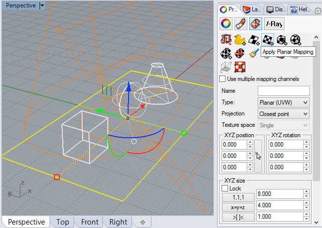
Next use the "XYZ size" to 2, 1, 0.5 to scale the bump map at 2 foot units in the direction of the x-axis.
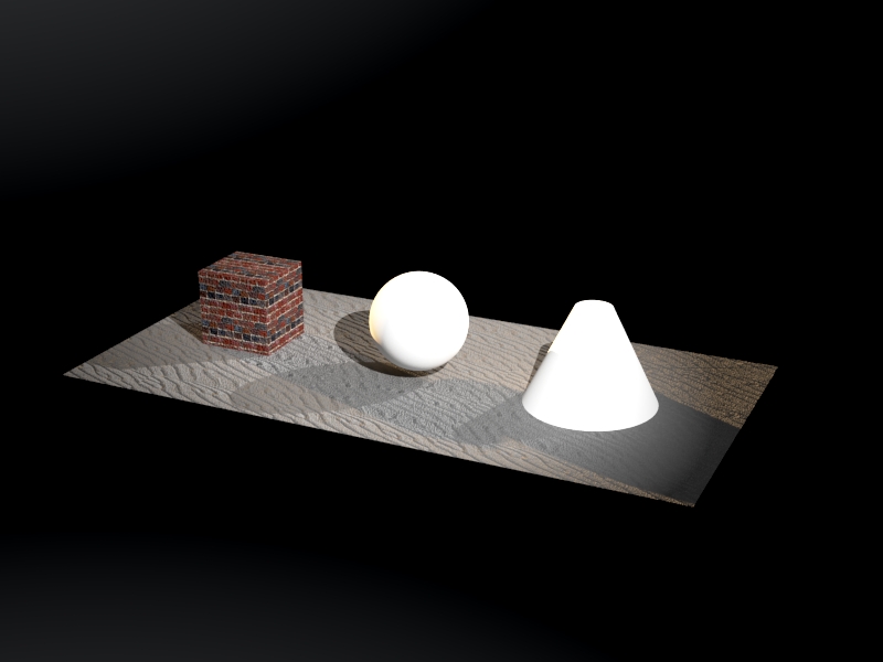
Apply the material to the ground surface, re-render the geometry in V-Ray amd note the bump map representation on the ground with a mid-level gray color.
To establish an alternative sand color, return to the material editor and the diffuse tab for "my-sand", select the dufuse color and then reset it to a light desaturated yellow.
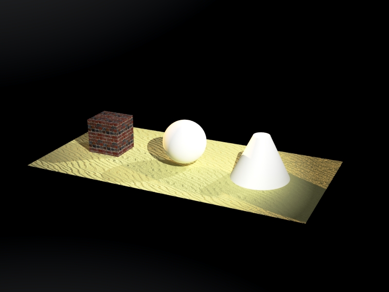
Re-render the image.
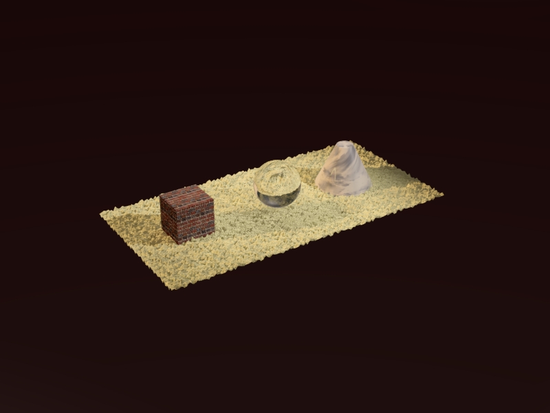
7. Alternatively, select off the "Bump" map option for the sand, select the check-box for Displacement within the same tab, and once again select the file "sand.jpg". Within the editor, change the value of the multiplier to 0.3.
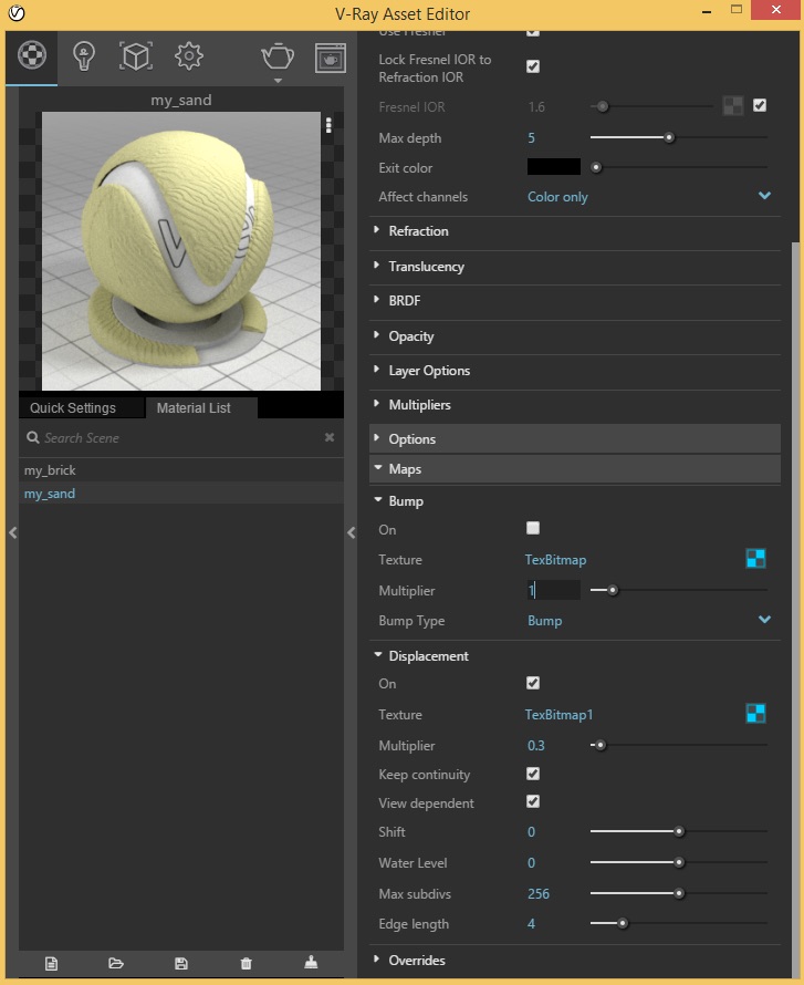
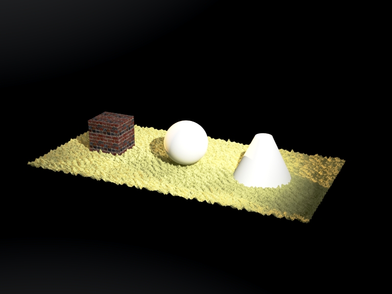
Render again and note the appearance of the sand with a more self-evident 3D appearance casting more realistic shadows and occluding the base of the brick cube and the cone. However, the rendering time also increases when switching from a bump map to a displacement map. The tradeoff between realism and rendering time needs to weighed in any decision to use the displacement map method.
7. Reflection map
Copy the examples folder "reflectionMapImages" from the classes server to your computer desktop.
Create a material named "myGlass" with an IOR of 1.55 as was done in workshop 6.
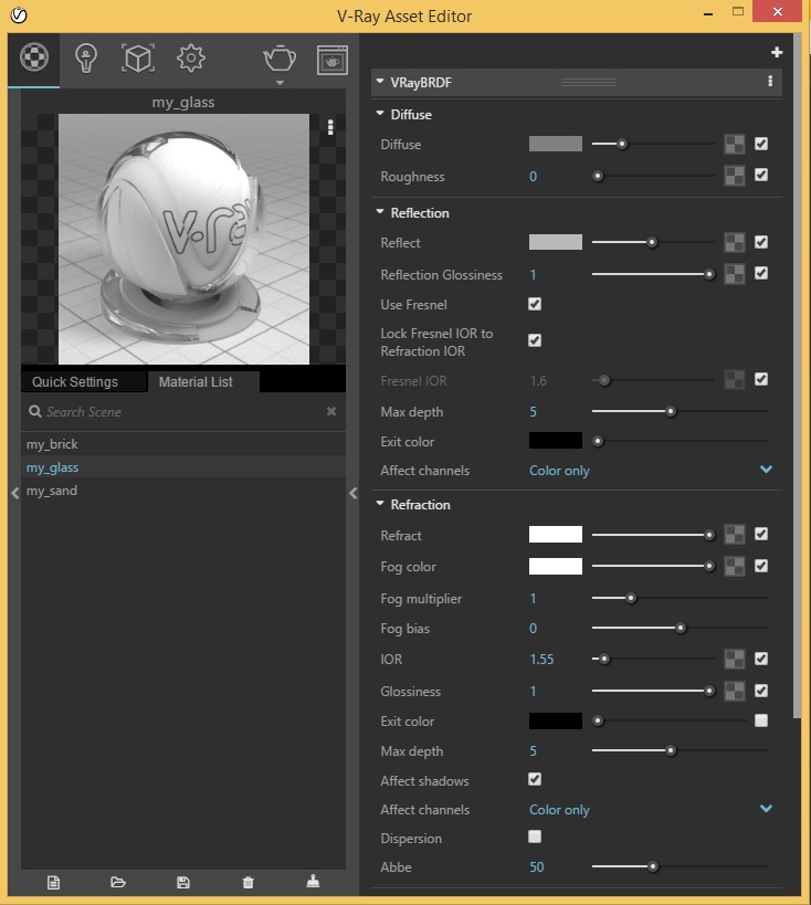
Apply it to the sphere, and render it.
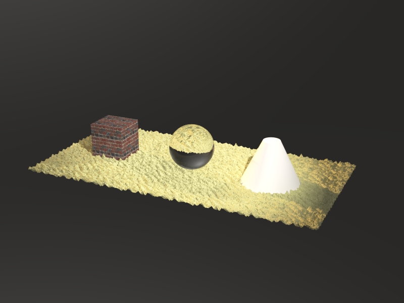
In the V-Ray material editor, go to the Reflection property for "myGlass" and select the checker-box adjacent to the word "Reflection":
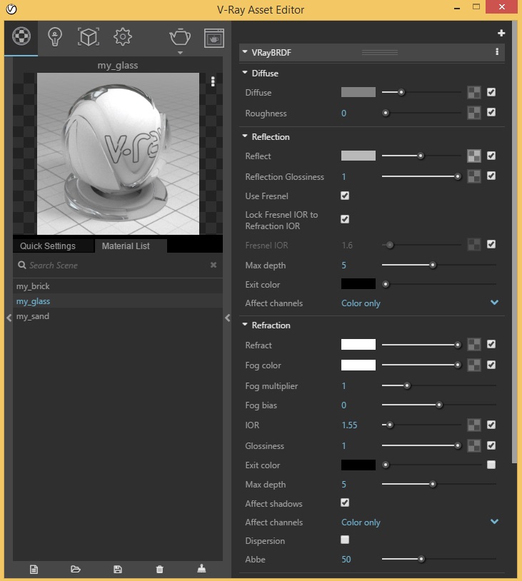
Select the image "cloulds-large.jpg" from the folder "reflectionMapImages":
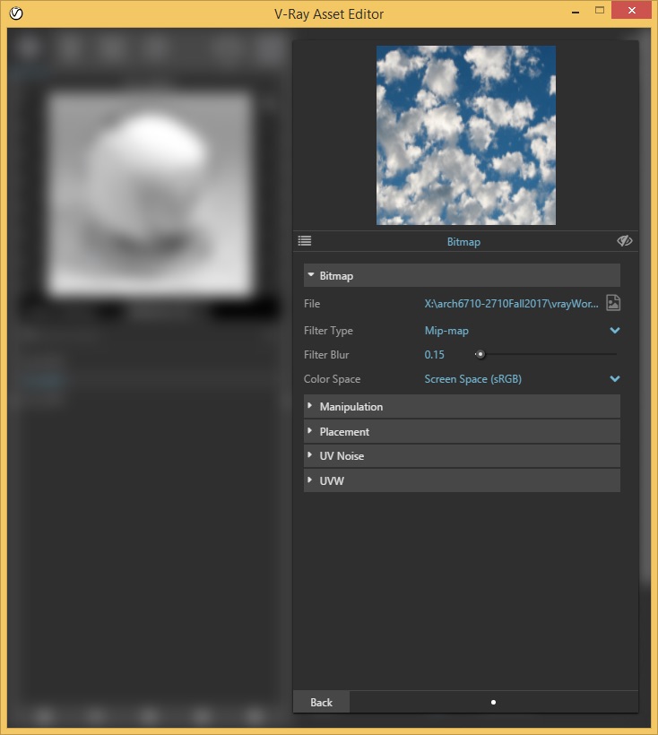
Unlock the Fresnal IOR value and change it to 4 to exadderate the reflection map.
Apply a spherical texture map to the sphere by selecting the sphere, going to the properties tab, selecting the texture map icon (cylindrical icon with orange and white checkered patten), and then snapping to the center of the sphere and point on the cirumference .
Render the result and note the sky reflection map at the base of the sphere.
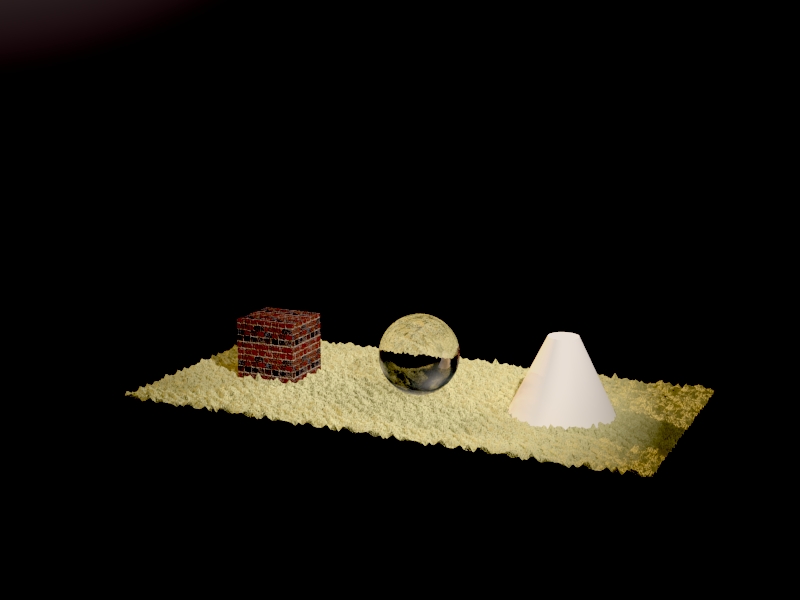
For the cone, create a material called "my_chrome" with a similar reflection layer. Change the diffuse color to light-grey, add the same reflection map. change the Fresnel IOR to 20 and leave the refraction color to black.
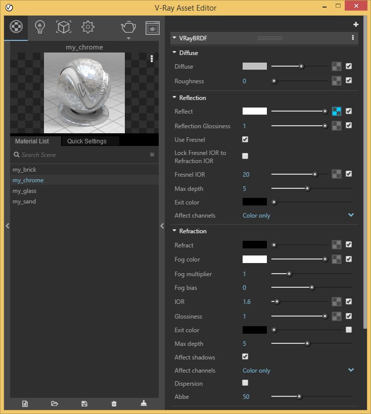
Next,add a cylindrical
texture map for the cone.
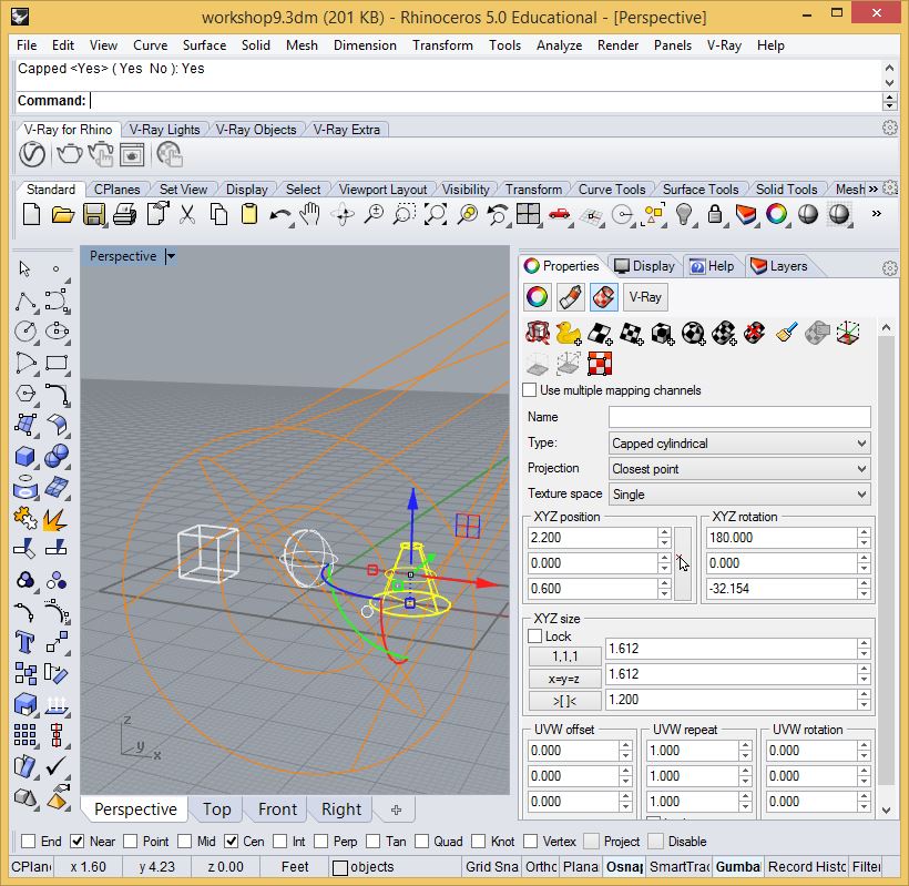
Add the material my-chrome to the cone, render.
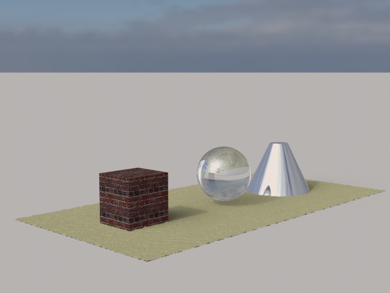
While these techniques for reflection mapping can achieve satisfying results especially with further adjustments, simulating a full context model is likely to be more effective. Turn of the reflection maps for the sphere and turn off the three lights. Add an infinite plane, sun and HDR sky per the techniques of workshop 7, and the same model yields the following rendering. (This sand displacement map multiplier was lowered to 0.05 for this rendering -see step 7 above).
8. Transparency Maps
Download the folder "transparencyMapImages" from the examples folder on the classes server.
The original images were obtained as free samples from a web site (the web address has been lost). Each of these images has been modified within Photoshop to be used in two pairs.
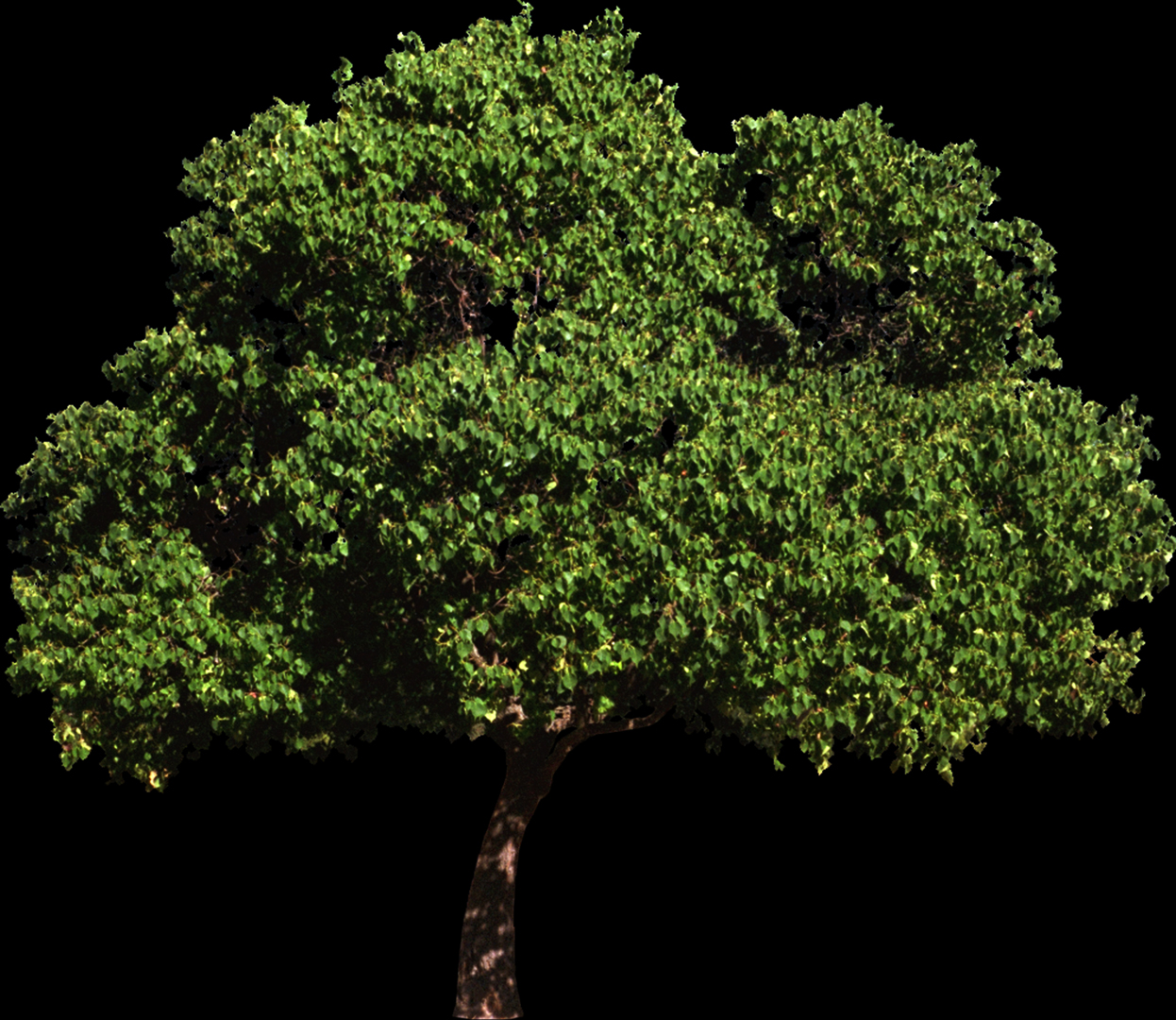





Each pair includes a photographed figure on black pixel background and a transparency mask of the same figure in black pixels on a white pixel background. In Photoshop, the pair of images was created in thee steps:
1. start with the original figure:

2. use the magic wand tool in Photoshop to select the pixels of the background, invert the selection to select the pixels of the figure, and then use the Photoshop fill tool to covert the the pixels to white:

Step 3.
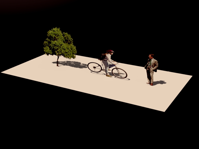
Create a new Rhino file with three vertical surfaces on a horizontal surface that are roughly proportional to the tree, bicyclist and pedestrian. Add a V-Ray sunlight.
Within the V-Ray material editor, create three materials named 'tree", "bicyclist" , and "pedestrian"
For the "bicyclist" material, go to the diffuse tab and select the letter checker box to the right of the word "diffuse", and within the "V-Ray" texture editor, select the option "Bitmap", and then select the file "biker.jpg" (positive image of bicyclist on a black backtround) from the transparencyMapImages folder, and change the value of "Filter Blur" to 0.
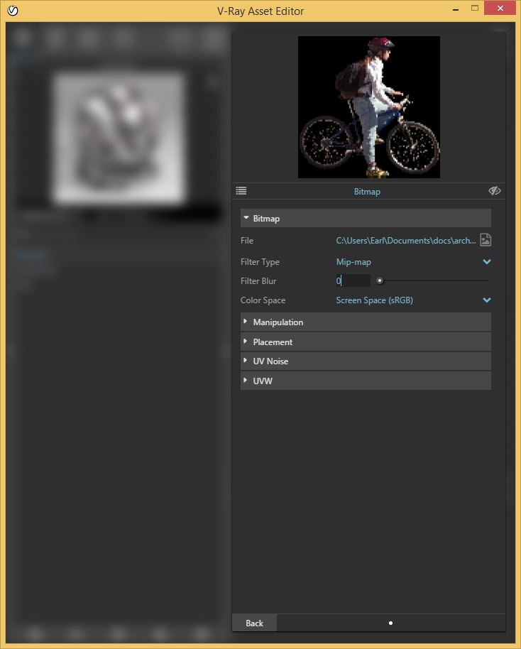
Similarly, go to the opacity tab and select the checker-box adjacent to the word "opacity".
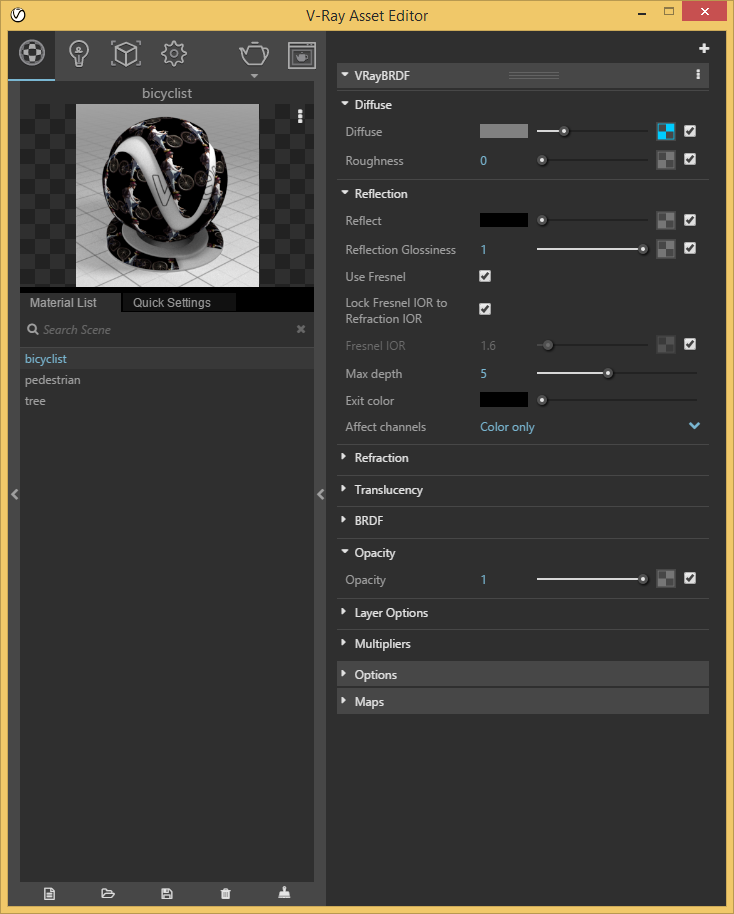
Next, within the "V-Ray" texture editor, select the option "Bitmap", and then select the file "bikeMat.jpg" from the transparencyMapImages folder, and change the value of "Filter Blur" to 0.
Do the same for the pedestrian and tree materials and render.
