COMPUTER
AIDED
ARCHITECTURAL DESIGN
Workshop 11 Notes,
Week of October 26 , 2020
V-Ray Grasshopper Animation of Moving Object, Camera and Light (FIRST DRAFT)
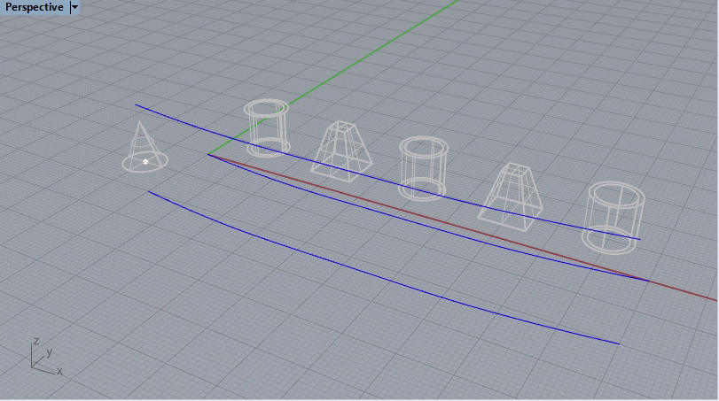
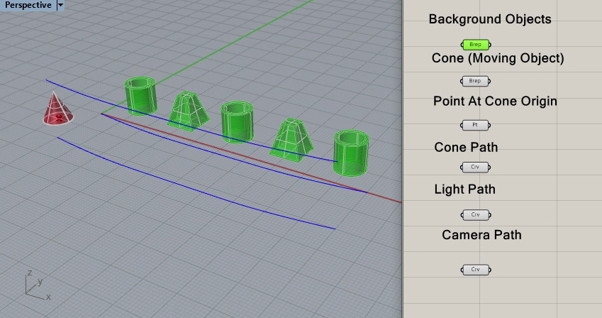
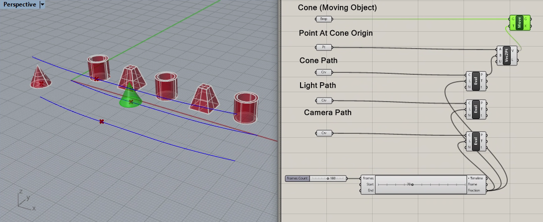
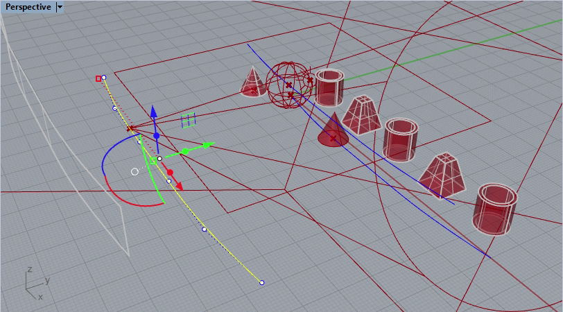
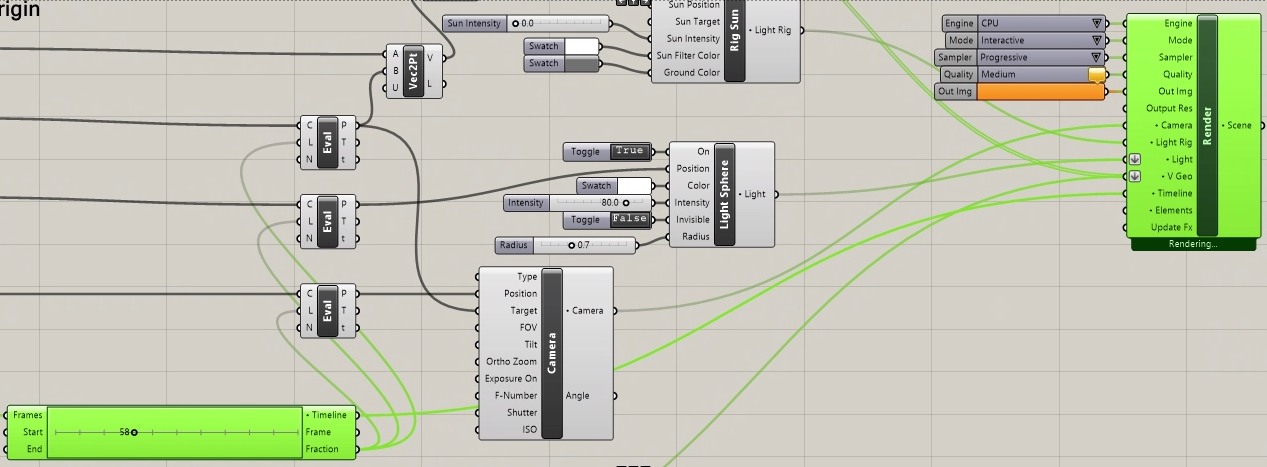
This set of workshop notes describes animation object, camera and light through V-Ray. We will be constuction a Grasshopper file for V-Ray that consiss of pathways and objects moving along those pathways, as indicated in the following preview image (select the image for a more detailed view).
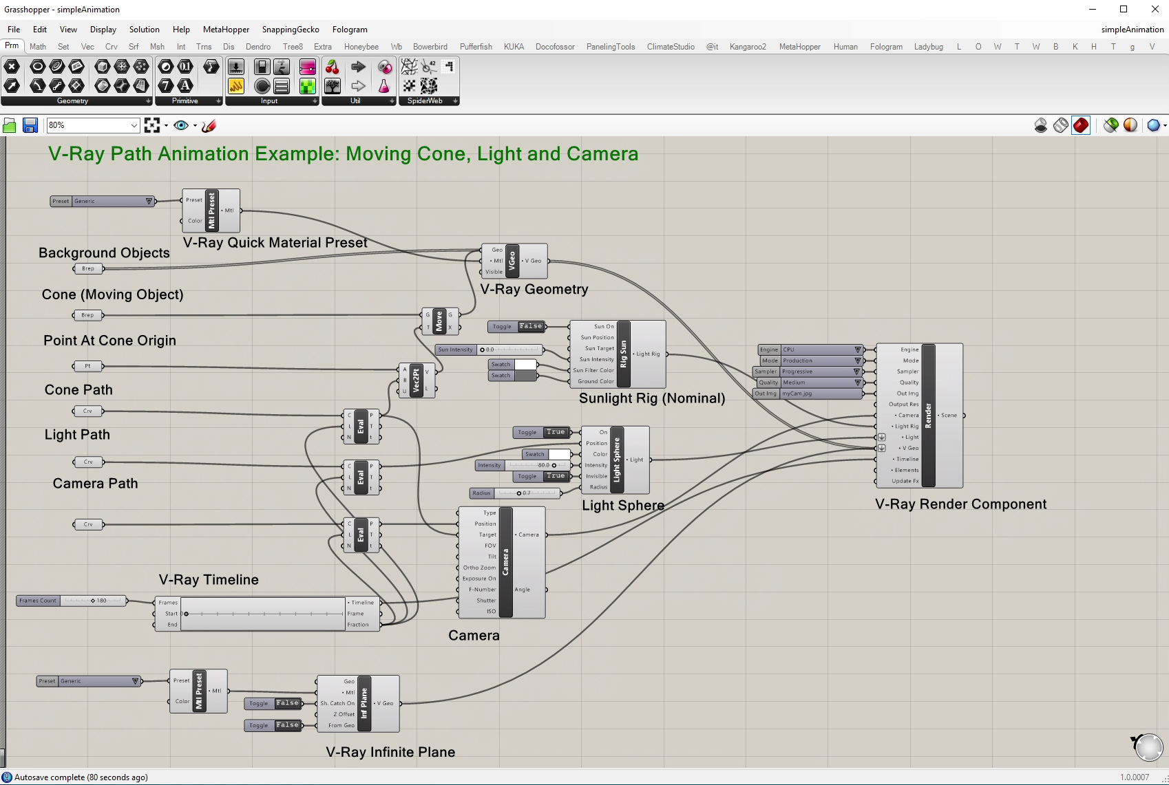
1, Create three control point cuves for the object path, camera path and light path.
Start by adding the three path curves each one created with control points placed from left to right, or make 3 copies of the same curve.
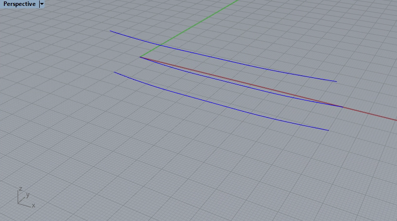
Add a cone with a point on its cental axis on the ground plane.
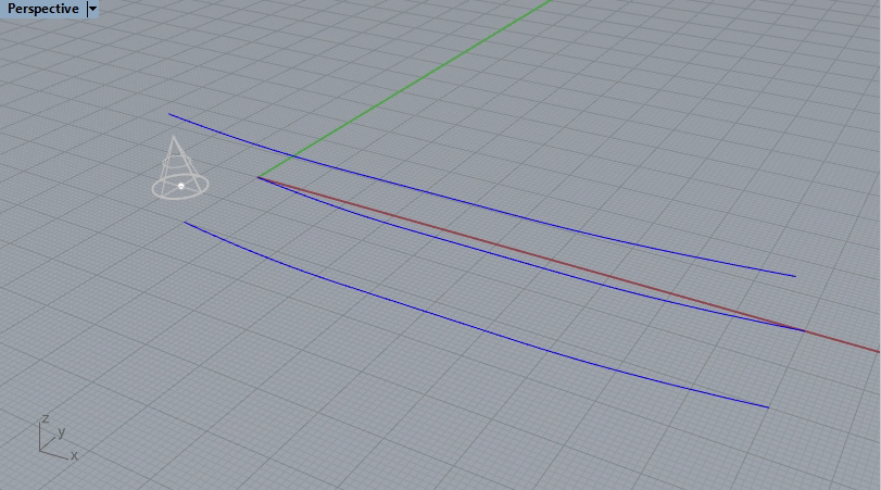
Add additional solid objects in the background along the path for visual reference.
2. Open Grasshopper. Create a curve parameter for each of the 3 path curves, a brep component and point component for the cone and point, and a brep for the remaining solid objects and make the corresponding connections for the entities in Rhino.
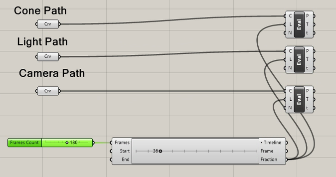
3. Within Grasshopper, in the "curves" sub-menu, select the evaluate curve component.
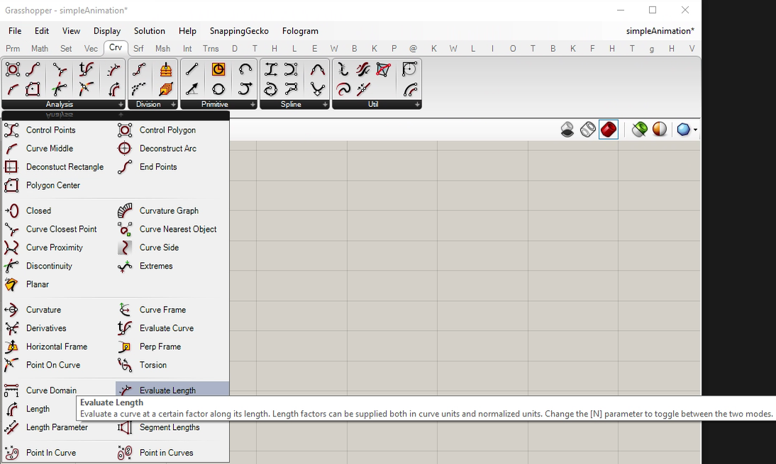
4. Place one in the canvas window for each of the three curves/
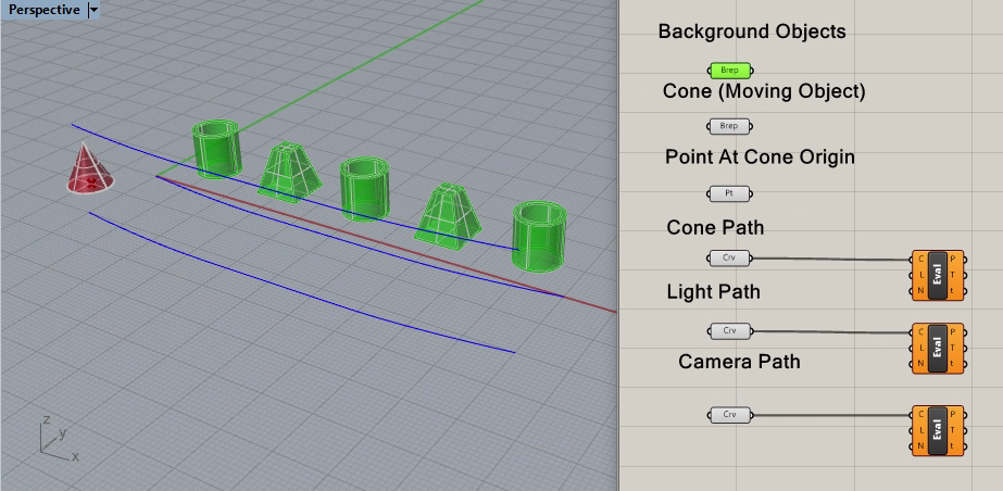
5. Go to the V-Ray Module within Grasshopper and select the timeline component.
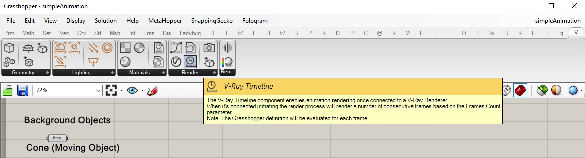
6. Place it on the lower left side of the Canvas window and connect it's output "fraction" the input "L" for each of the three eval components. The fraction is a percentage of the animatino complete from 0 to 1. Notice that a point is generated along each of the three curves accordingly.
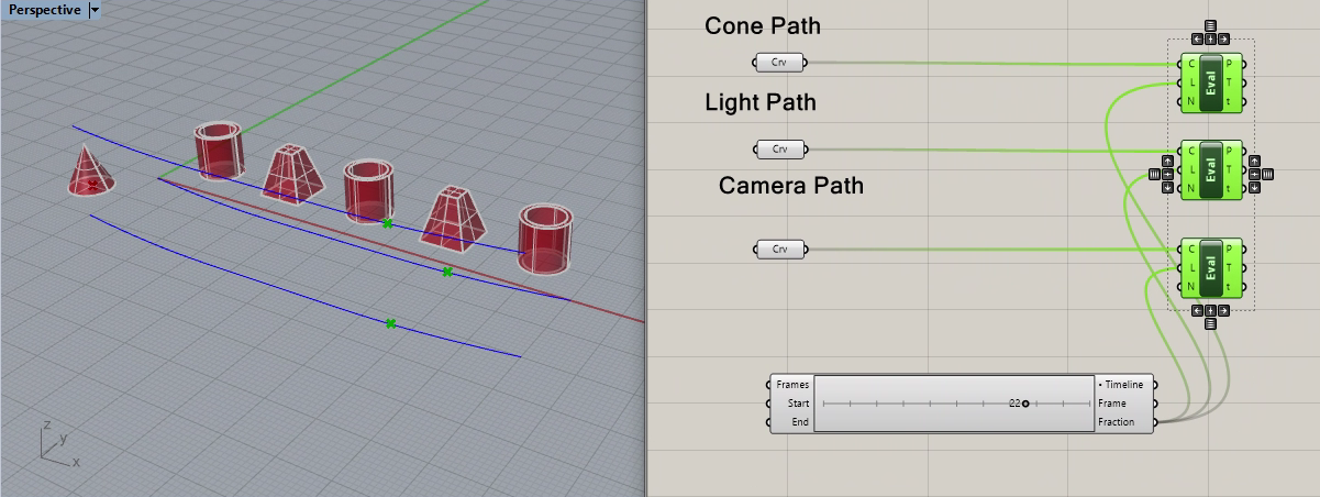
Add a numerical slider that runs from 2 to 360 frames, set the current value to 180, and plug it into the "Frames" input port of the timeline.
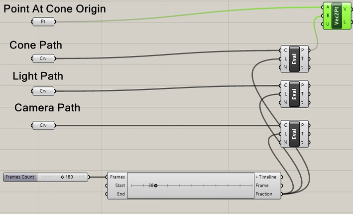
7. Add a vector component from the cone origin point component the cone path eval curve output "P" (point along the curve) output port.
8. Under the Grasshopper tansform "trns" tab, add a "Move" component to the canvas window . Connect the output of the Cone "brep" to the "G" input port of he "move Component. Aslo connect the "v" ouput port of the "Vec2pt" component to the "T" input port of the "Move" component.
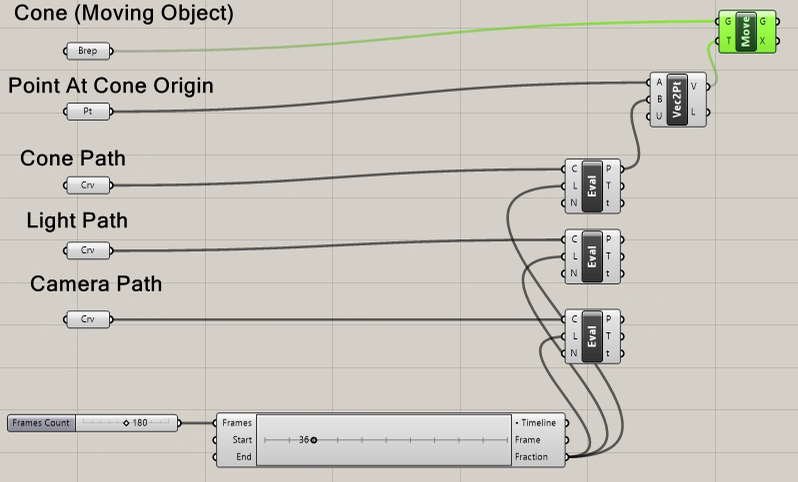
9. Note that the cone begins to travel along the cone path control path by moving the timeline frame marker in the V-Ray Timeline.
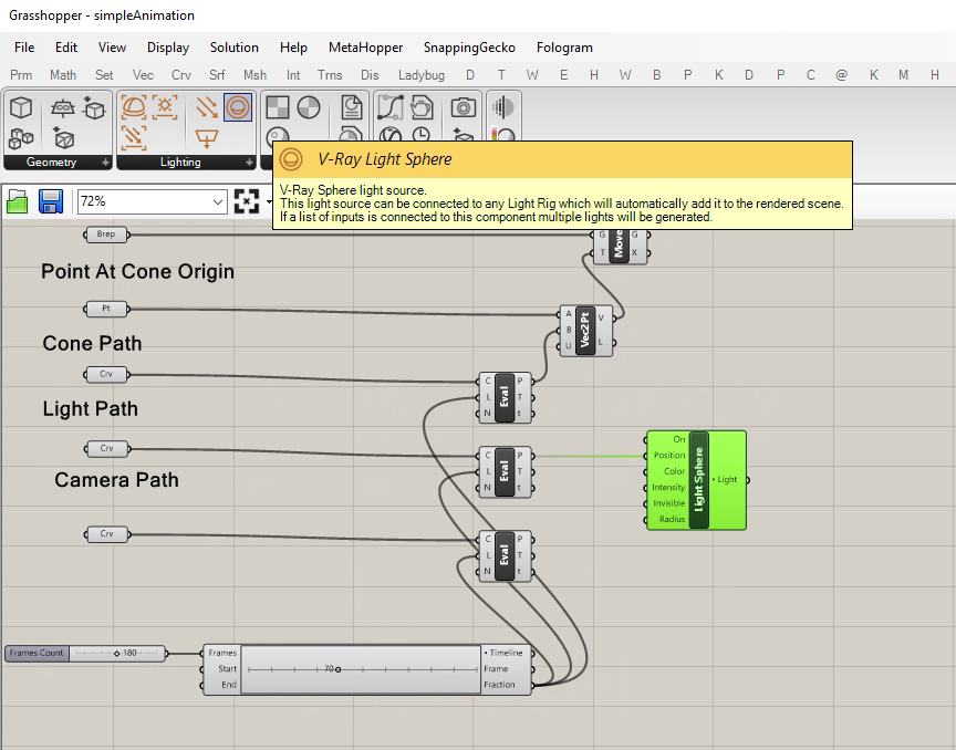
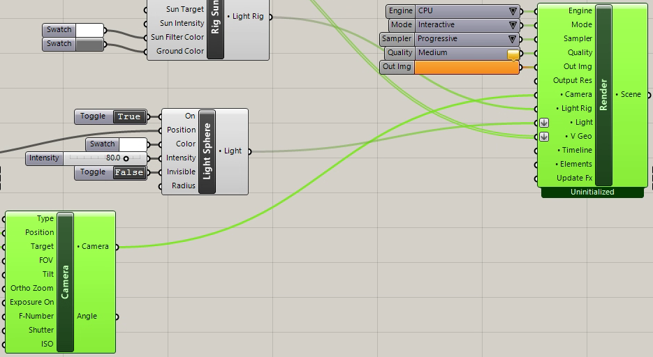
10. Add a V-Ray Light Sphere component and connect its input port "Position" to the output port "P" of the eval curve component for the light path control curve.
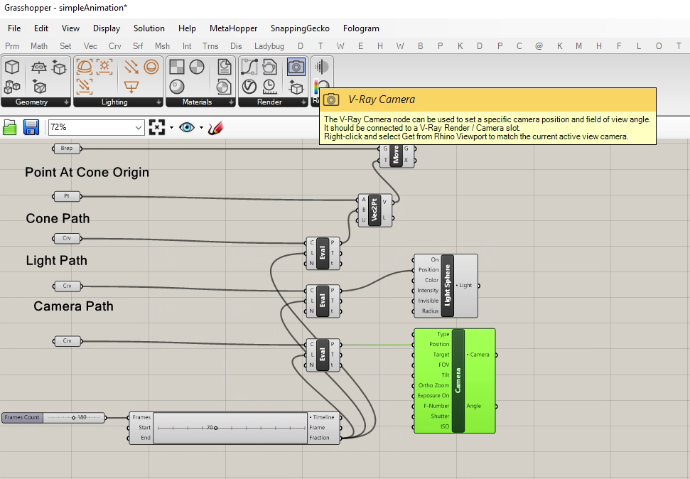
11. Add a camera component and connect its input port "Position" to the output port "P" of the eval curve component for the camera path control curve.
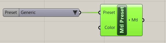
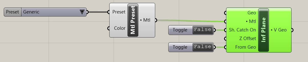
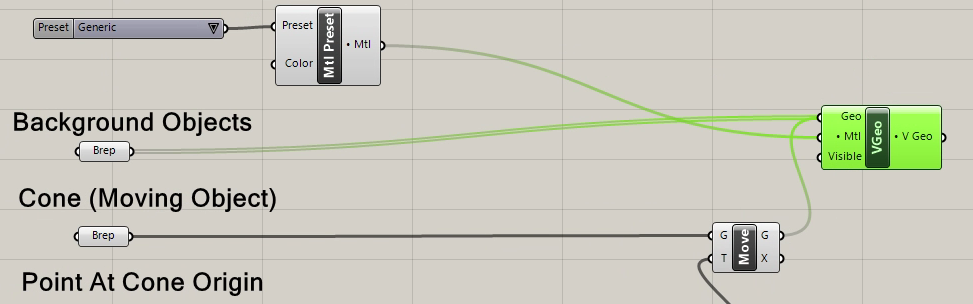
12. Add a V-Ray Material Preset component (simple material definition) to the Grasshopper Canvas Window.
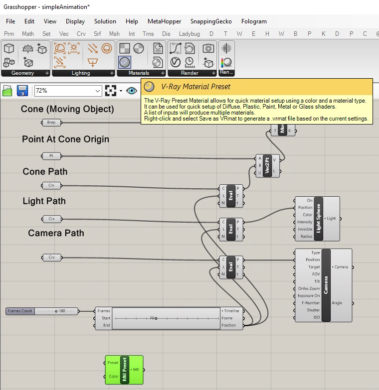
13. Right mouse button click on the V-Ray Material Preset component and select the "Show Controls" option.
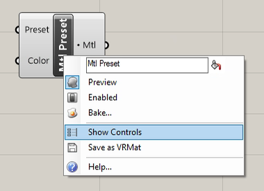
14. The last step reveals the input type material "Generic" and has a defaut color of dark gray.
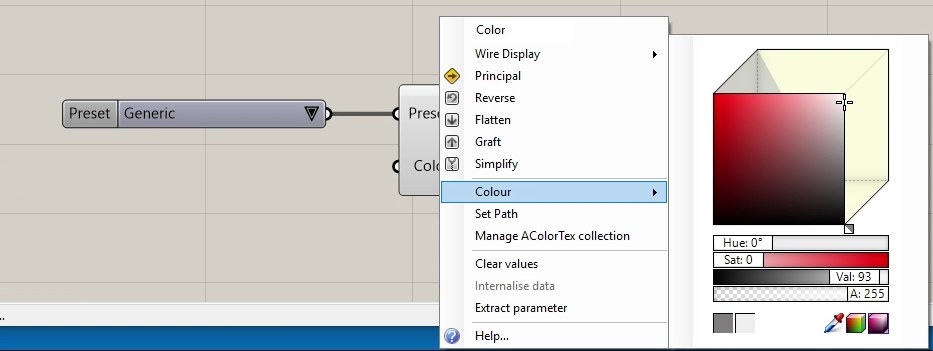
15, Select the color menu item with the right mouse button and adjust the color value to off-white as in the dialog below
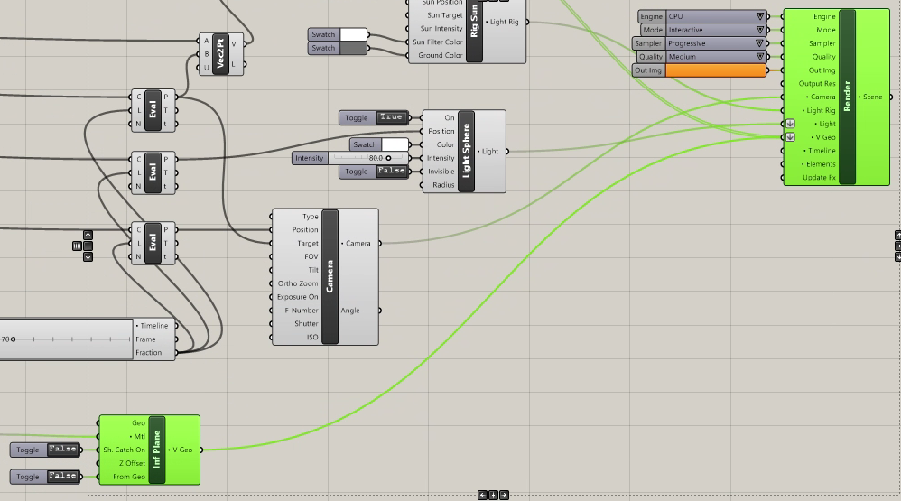
16. Now add a V-Ray Infinite Plane component to the canvas window.
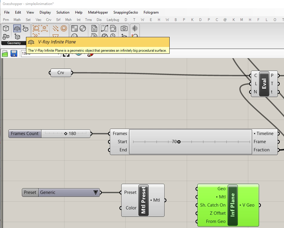
17. Right click on the infinite plane component and open its "Controls". The Boolean "True" or "False" Toggles are revealed. Switch both to "False".
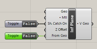 .
.
18. Connect the V-Ray Material Preset output port named "Mtl" to the corresponding "Mtl" input port of the Infinite Plane.
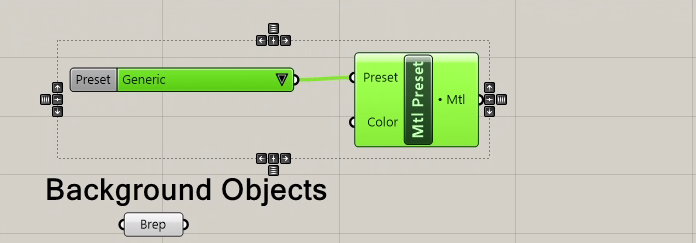
19. Copy the V-Ray Material Preset and it's controls to the area of the canvas window adjacent due the "Brep" component for the background objects.
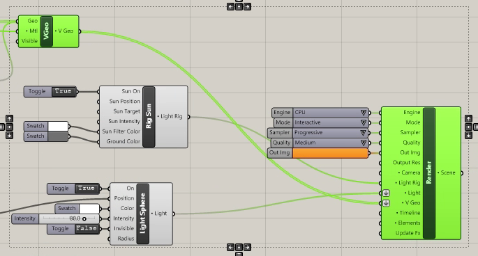
20. Add a V-Ray Geoemetry component to the right of the "Move" component for the Cone object.
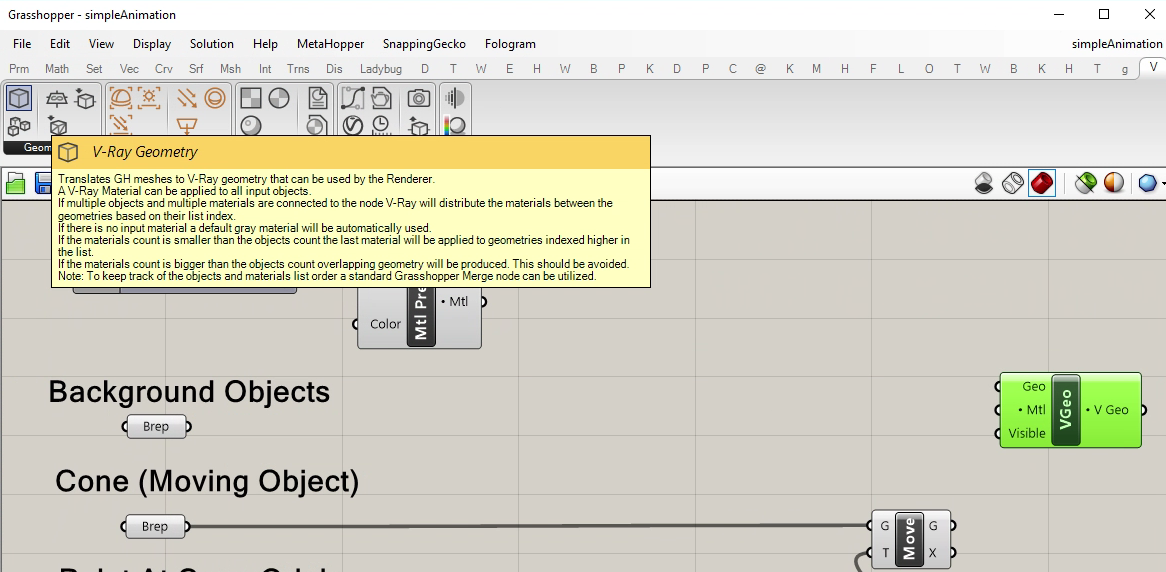
21. Connect the "Brep" for the background objects to the "G" output port of the "Move" component. Similarly connect the "Brep" for the cone objects to the "G" output port of the "Move" component. In addition, onnect the output "Mtl" port of the "Mtl Preset" component to the "Mtl" input port of the "V-Ray Geometry" component.
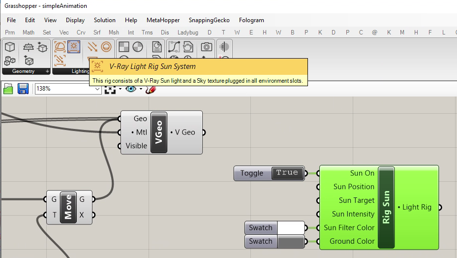
22. Add a V-Ray Sunlight Rig System to the upper right of the V-Ray Light Sphere component.
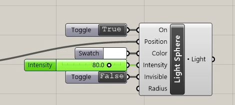
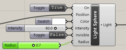
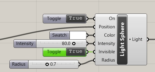
23. Right-clock on the Light Shere component to add its conrol panels. Also, add a number slider ranging in values from 0.0 to 100.0 with a current value set to 80.0 and connect its output port to the "Intensity" input port of the "Light Sphere".
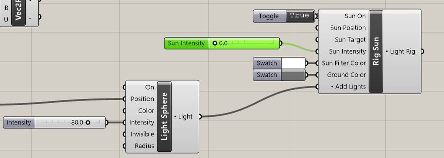
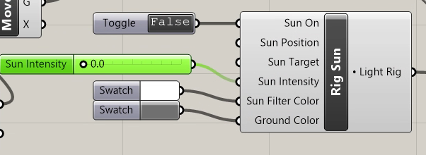
24. Copy the number slider, set the copy slider's value to 0.0, and connect its output port to the "Sun Intensity" input port of the V-Ray Sunlight Rig System.
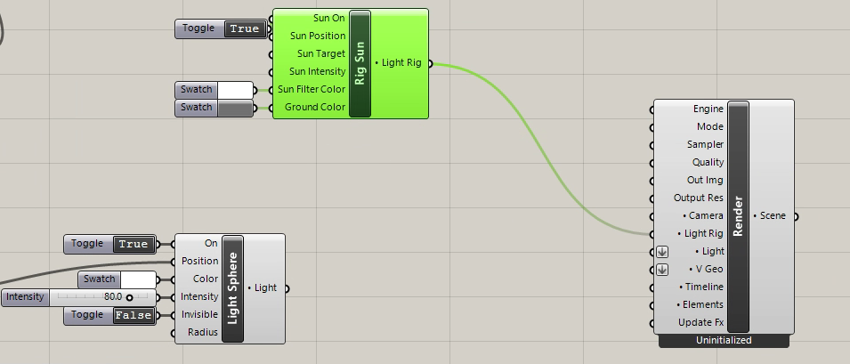
25. Add a V-Ray Render component to the right of the Sun Rig.
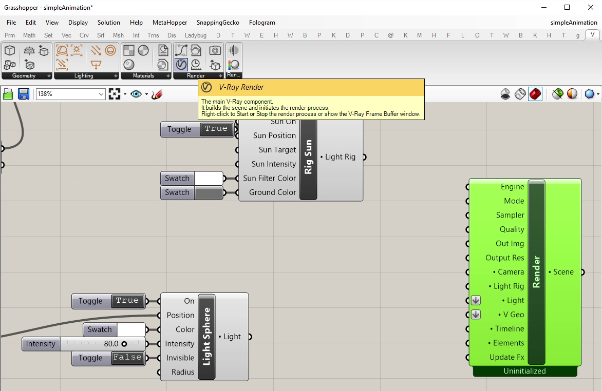
26. Connect the output port of the V-Ray Sunlight Rig System to the "Light Rig" input port of the V-Ray Render component.
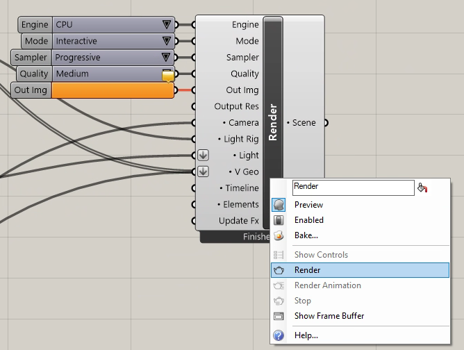
27. Connect the output port of the Light Sphere to the "Light" input port of the V-Ray Render component. Right Click on the render component and show it's controls.
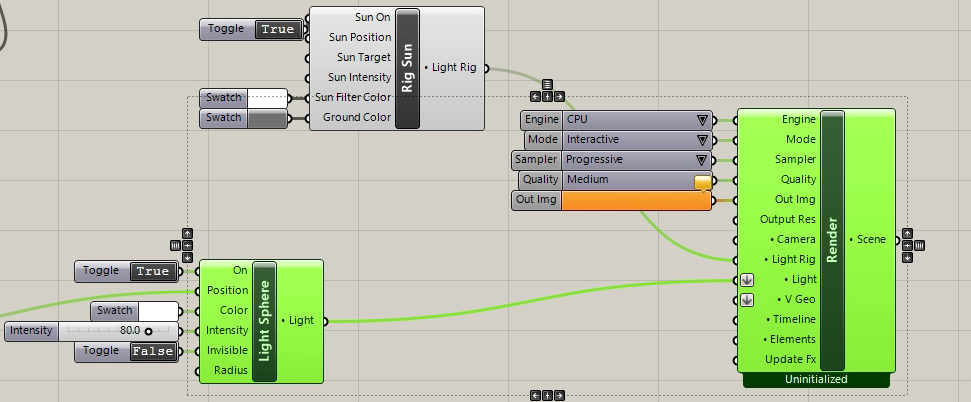
28. Change the render component "Mode" to "Production" and connect the V Geo and Infiinite Plane output ports to the "V Geo" input port of the V-Ray Render component.
29. Connect the cone path output port "P" the the Camera' component "Target" input port.
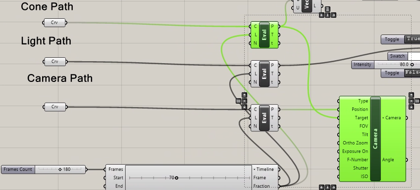
30. In turn connect the "Camera" component "Camera" output port to the "Camera" input port of the V-Ray Render component.
31. Add the infinite plane output port to the to the "V Geo" input port of the "V-Ray Rendering" component.
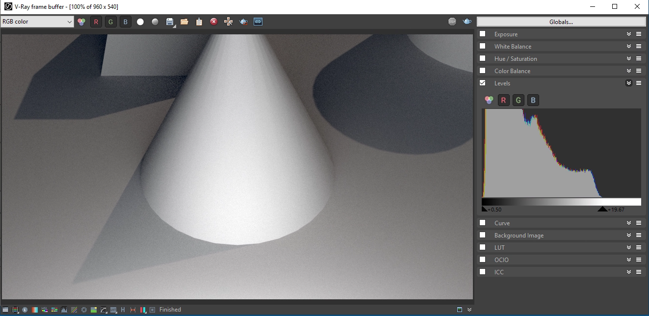
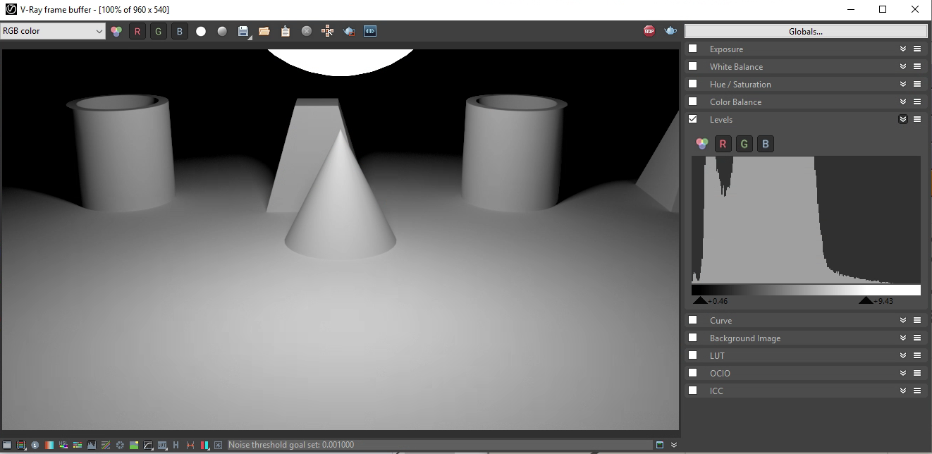
31. Set the frame number to 60. Right mouse click on the Render component and choose the "Render" option to render a single image from the camera's point of view.
32. Adjust values for "Levels" and review the result.
33. Use the "Gumball" too to adjust the camera path and spherical light path placing them further away from the cone path as needed take in a wider view.
34. Add a numerical slider with a range of value froms 0.0 to 2.0 to the "intensity" input port of the Sun rig and set its value to 0.
35. Add a numerical slider to the "radius" input port of the light sphere with a range of values of 0.0 to 2.0 and set its value to 0.7
36. Re-render the view to see if the adjustment is closer to the view angle and view framing you desire. Note that the spheritical light is visible in the upper part of the view.
35. Connect the V-Ray Timeline output port to the V-Ray Render component "Timeline" input port.
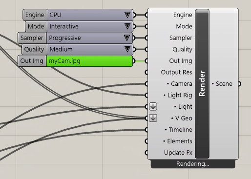
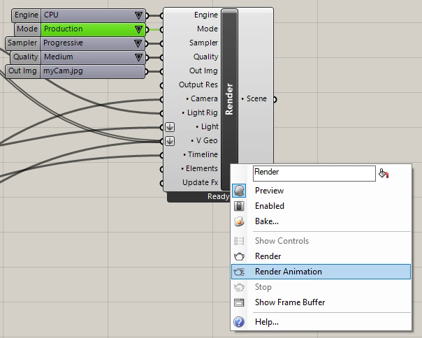
36. Double click on render component "Out Img" file controls tool to select a file type, and to name (e.g, "mycam.jpg") and choose its folder location (e.g., "frames"). The "jpg" format is recommended as the default image file format.
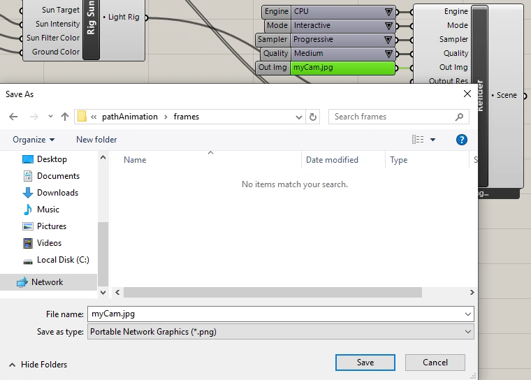
37. Note that the file format has the name"myCam.jpg". The individial animation frames will be named "myCam.0001.jpg", "myCam.0002.jpg" etc..
38. Change the "Mode" control from "Interactive" to "Productive", and then right - click on the "Render" componet and select the "Render Animation" option to render he animation.
39. Render, compile, and view the resulting animation. Note we will cover the animation file frame assembly to complied movie file process through OpenShot video editing software per separate notes.
40. Right mouse button click to "Light Sphere" component, use the "Show Controls" tools, and then toggle Boolean control for the "Invisible" property to "True".
39. Render, compile and view the resulting animation and note that the sphere is no longer visible.