COMPUTER
AIDED
ARCHITECTURAL DESIGN
Workshop 13 Notes,
Week of October 31, 2022
ROOF GEOMETRY EXAMPLES (ROUGH FIRST DRAFT)
This workshop introduces a number of examples for generating roof geometry in the abstract. Some of the techniques used in examples 1 and 2 below are adapted from a space frame tutorial video for Grasshopperprepared by parametrichouse.com. The notes below demonstrate a more limited approach in order to avoid the complexity of some of the connection details in the video. Watch the video to learn how this is done in greater depth. The example 3 below is independently developed for this workshop.
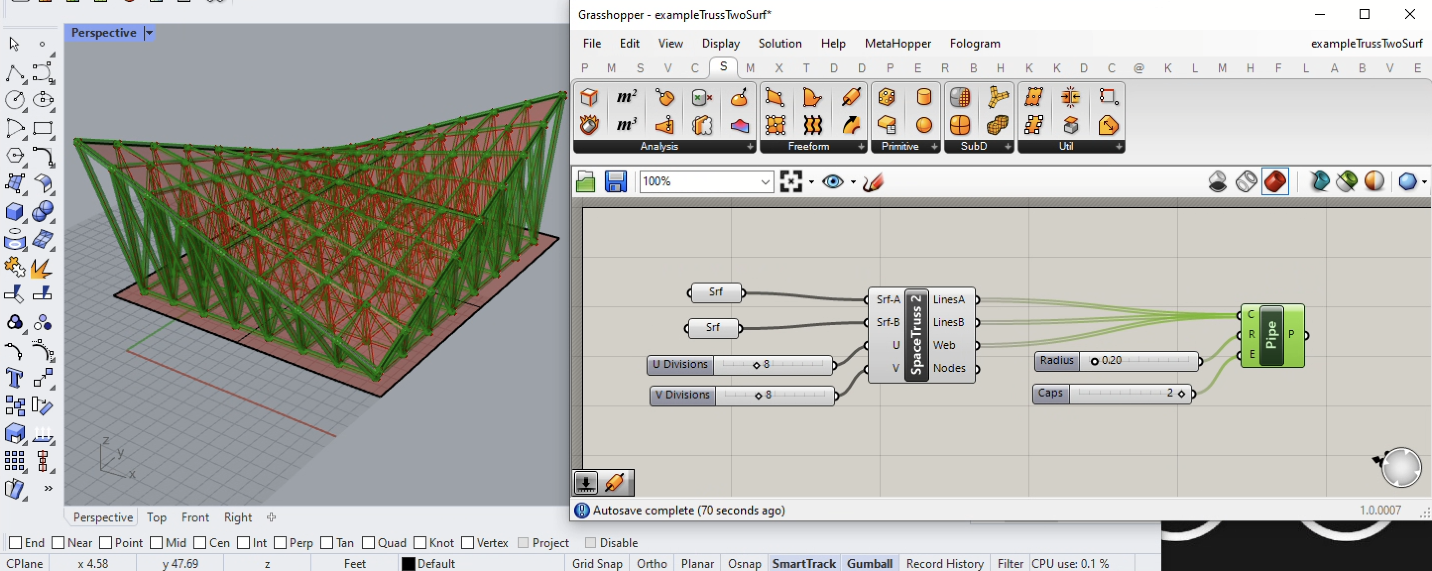
Example 1. Simple Saddle Shape With Space Frame BetweenTwo Surfaces.
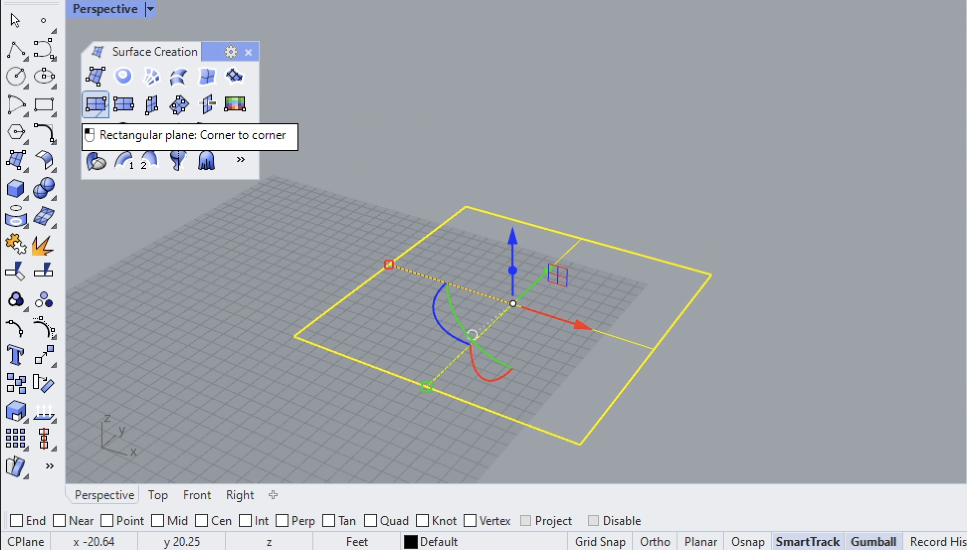
1. Create a rectangular plan surface on the ground, using corner points 0,0 and 20, 20 and duplicate it.
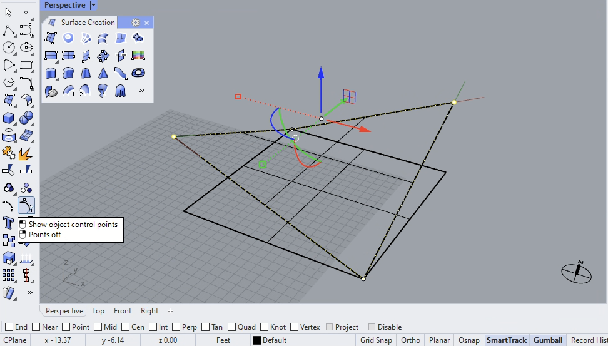
2. Create a simple saddle shape using by raising the diagonally opposite object control points of a flat rectangle surface, as demonstrated in earlier Workshop Notes 1, Part 14.
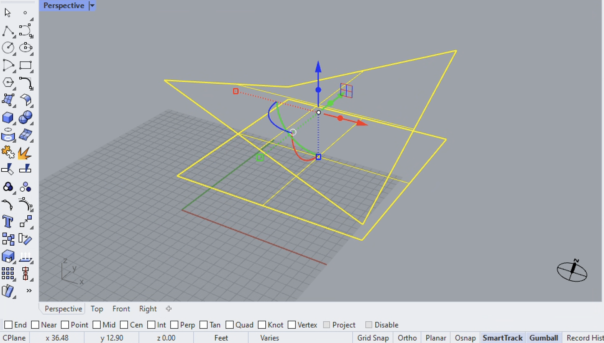
3. Move both surfaces above the ground plane and separate them vertically such that the upper surace and lower surface do not intersect with one another.
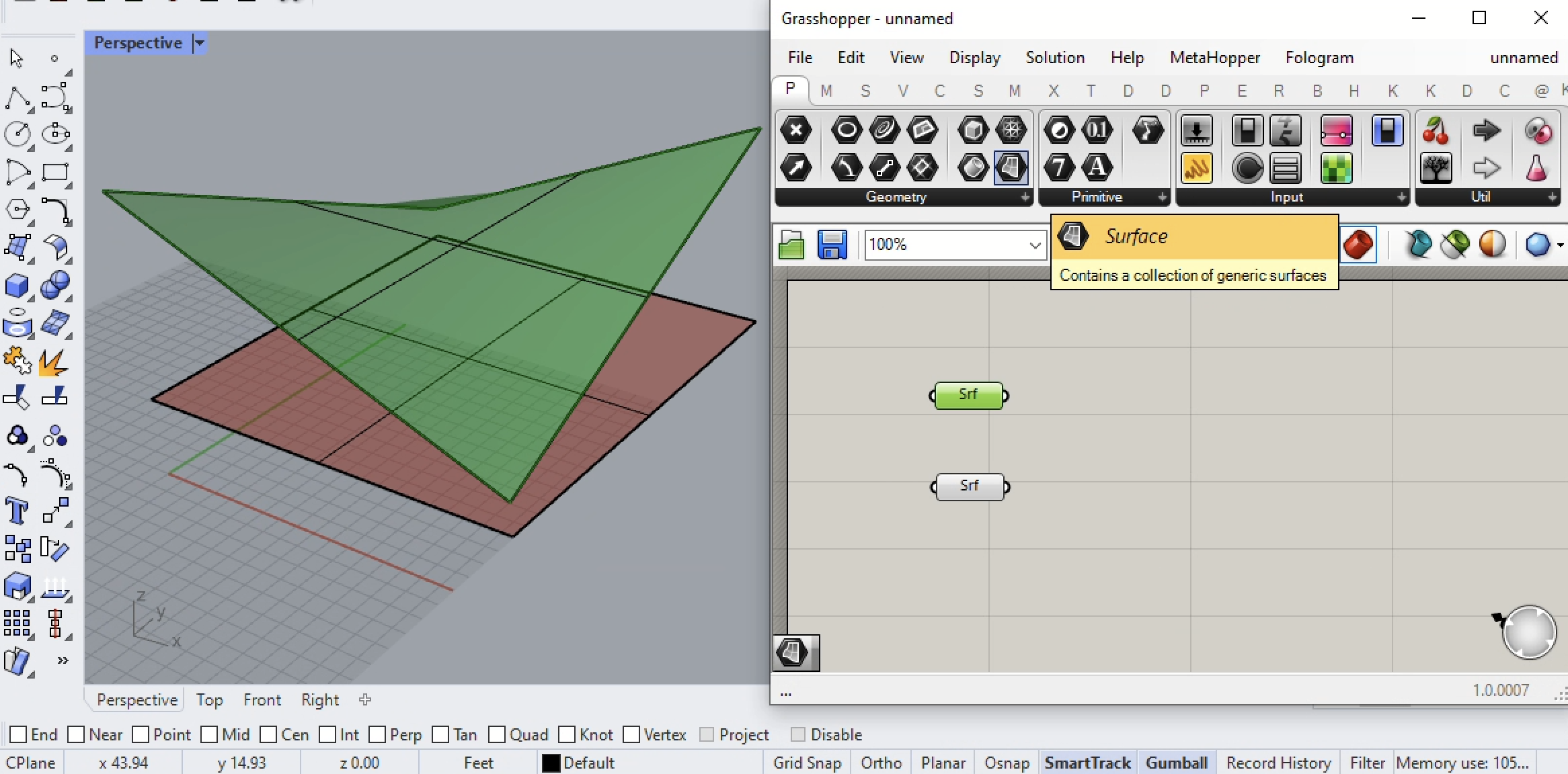
3. Open grasshopper and import both surfaces with a surface component from the the params/geometry tab.
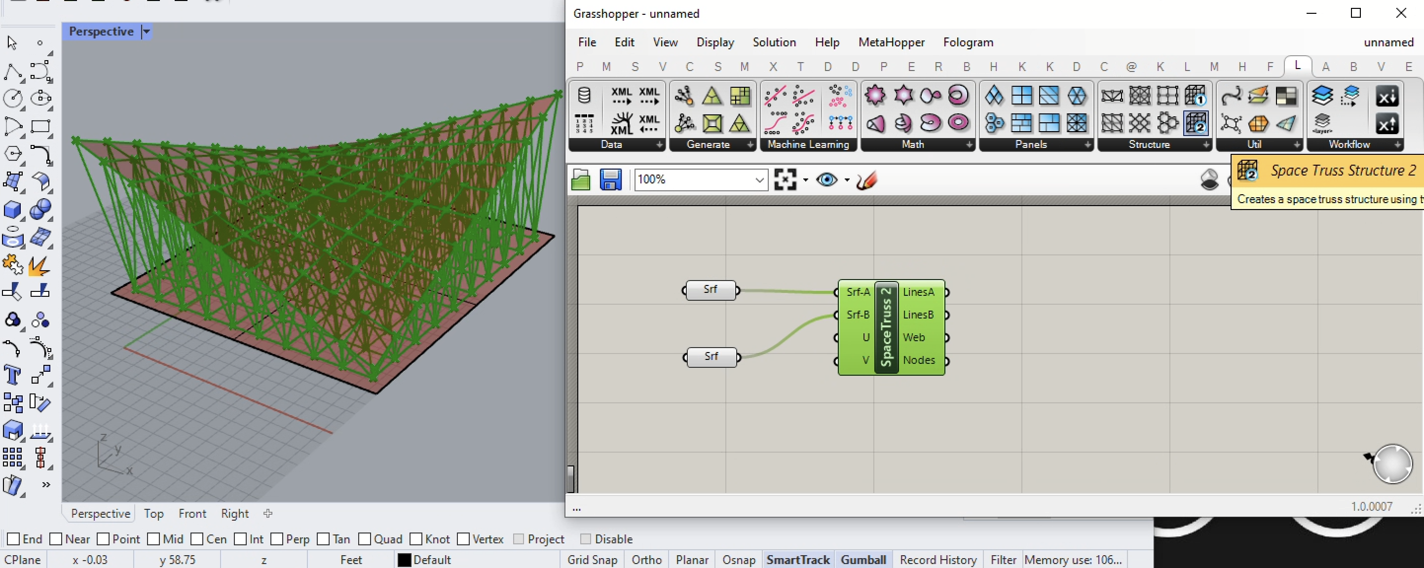
4. Go the lunch box plugin to grasshopper, add the truss 2 component, and then input the saddle and lower surface to inputs Srf-A and Srf-B to create the initial truss as shown below.
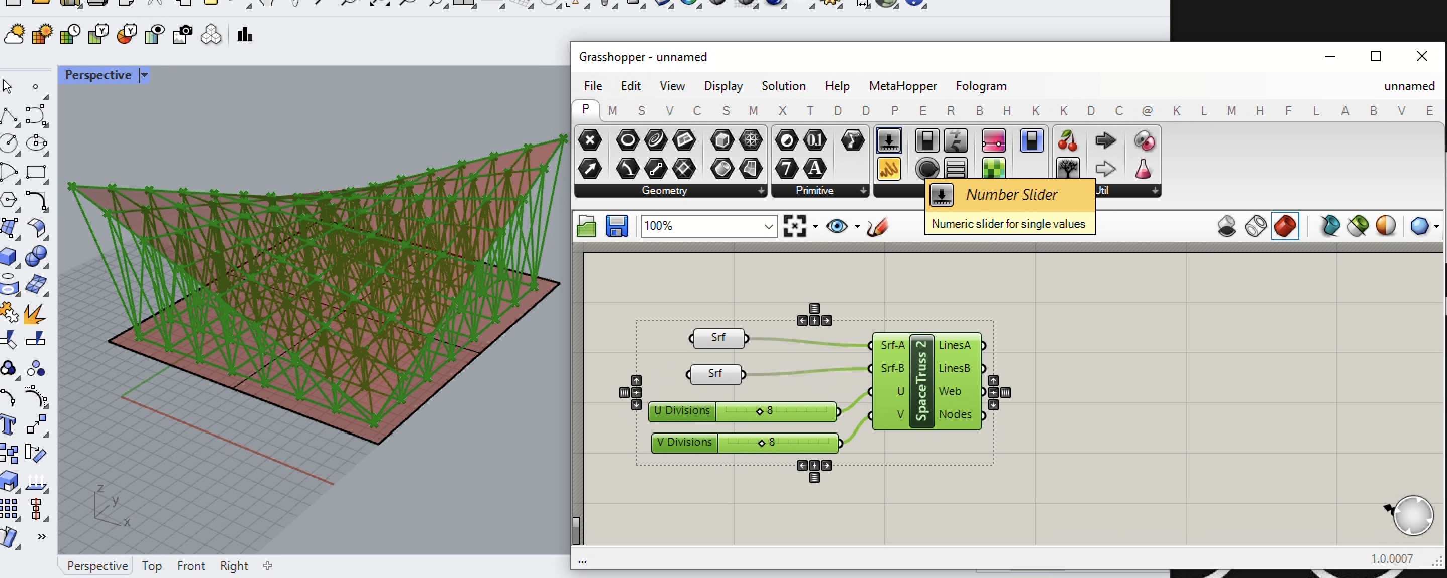
5. Add numerical input sliders to control the number of truss members in the U and V direction on the two surfaces to become 8 x 8.
6. Go to the surfaces tab, add a pipe surface, and setup a decimal number slider for radius such as 0.2, and an integer number slider from 0 to 2 to set the type cap to 2 (rounded) as shown below.
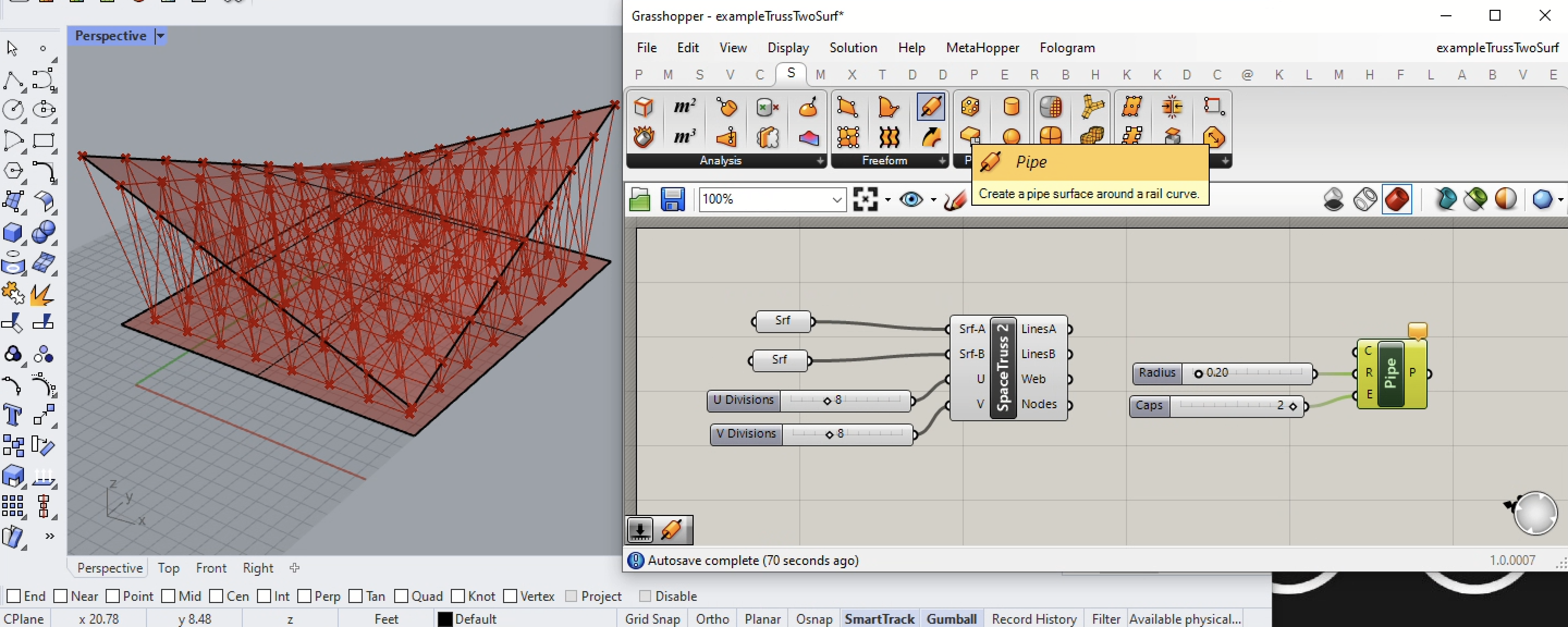
7. Now connect the LinesA, LinesB, and Web output ports on the SpaceTruss2 component to the "C" import port to the Pipe Component.
See example 3 below to see how the SpaceTruss 2 / Nodes output port can be used to general columns below the structure.
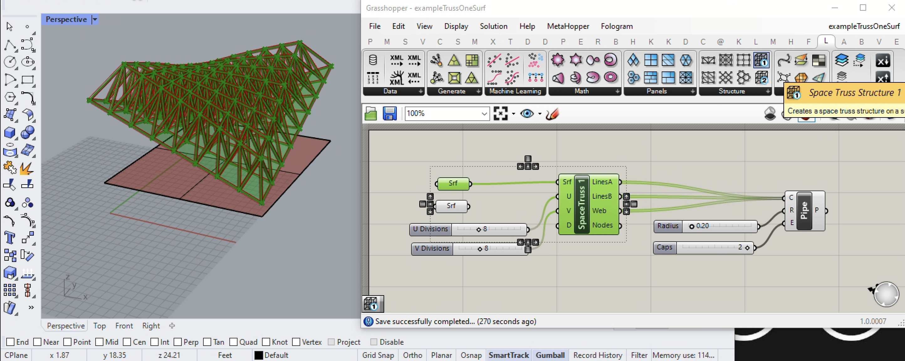
Example 2. Simple Saddle Shape With Space Frame From One Surface
1. Following the same approach, from the Lunch Box plugin to Grasshopper replace the Space Truss 2 component with a Space Truss 1 component connect the saddle surface only. Setup the same inputs to the Pipe component as was done in example 1. However, note that the truss appears above rather than below the saddle shaped surface.
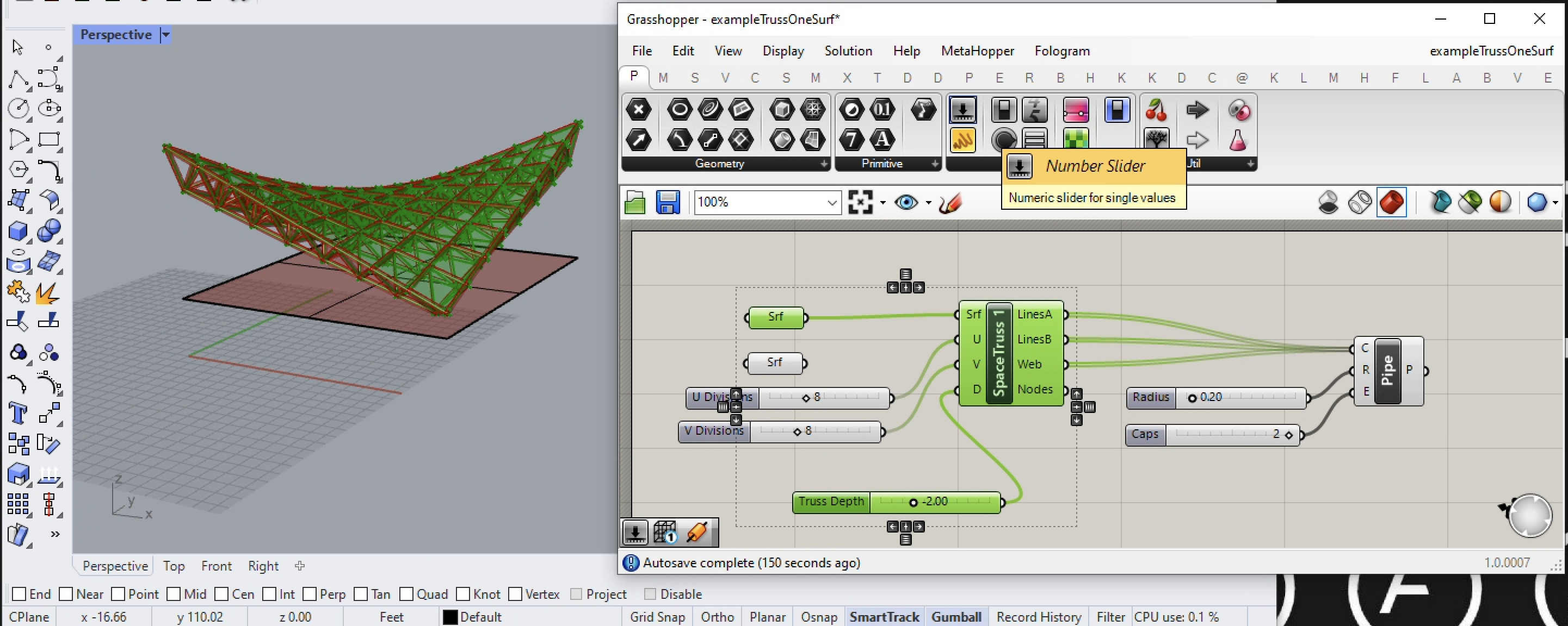
2. To reverse the direction of the truss, add a decimal Number Slider with the value of -0.2 as input to the D input port of the SpaceTruss 1 component. The negative numerical reverse the truss direction to the underside of the saddle surface.
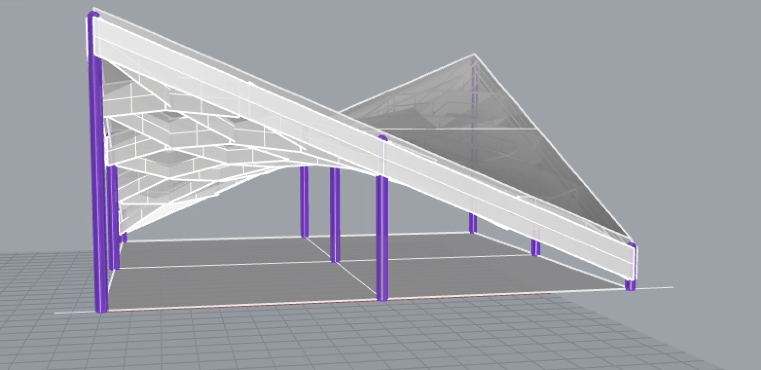
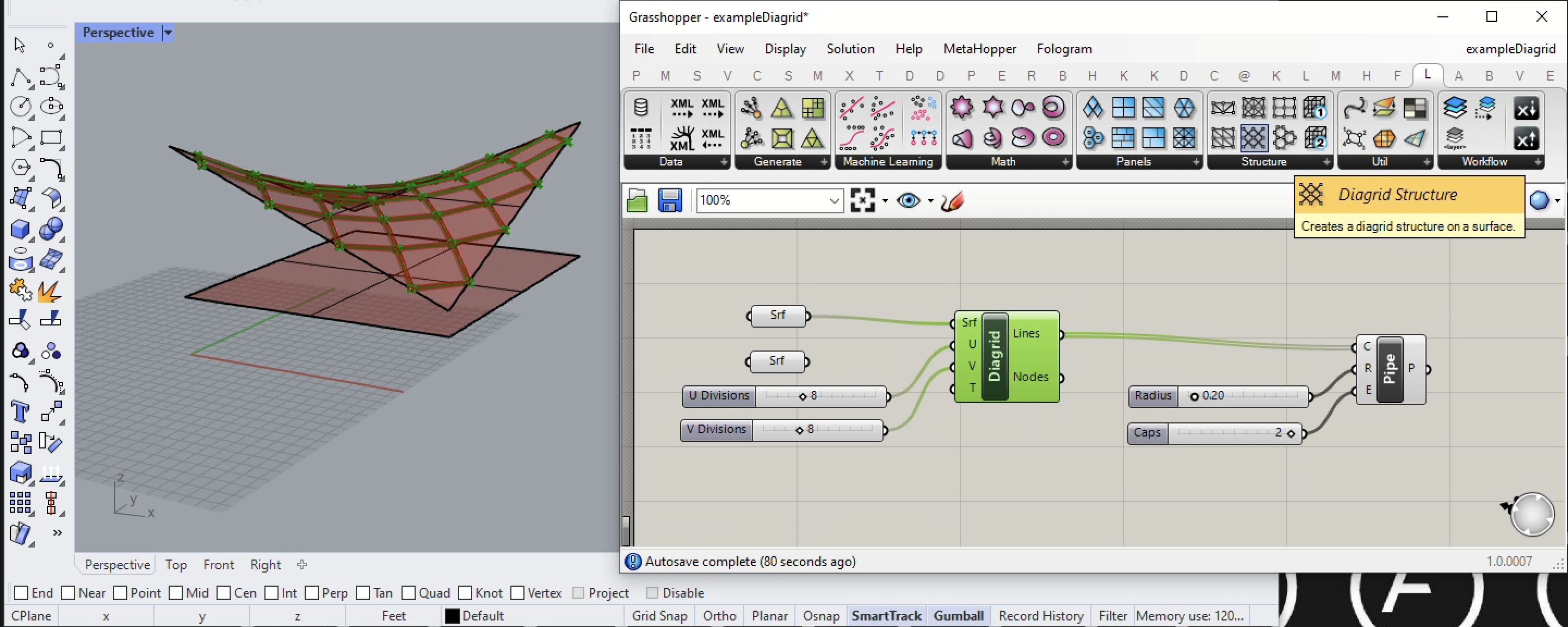
Example 3. Simple Saddle Shape With Diagrad, Support Structure and Columns Below.
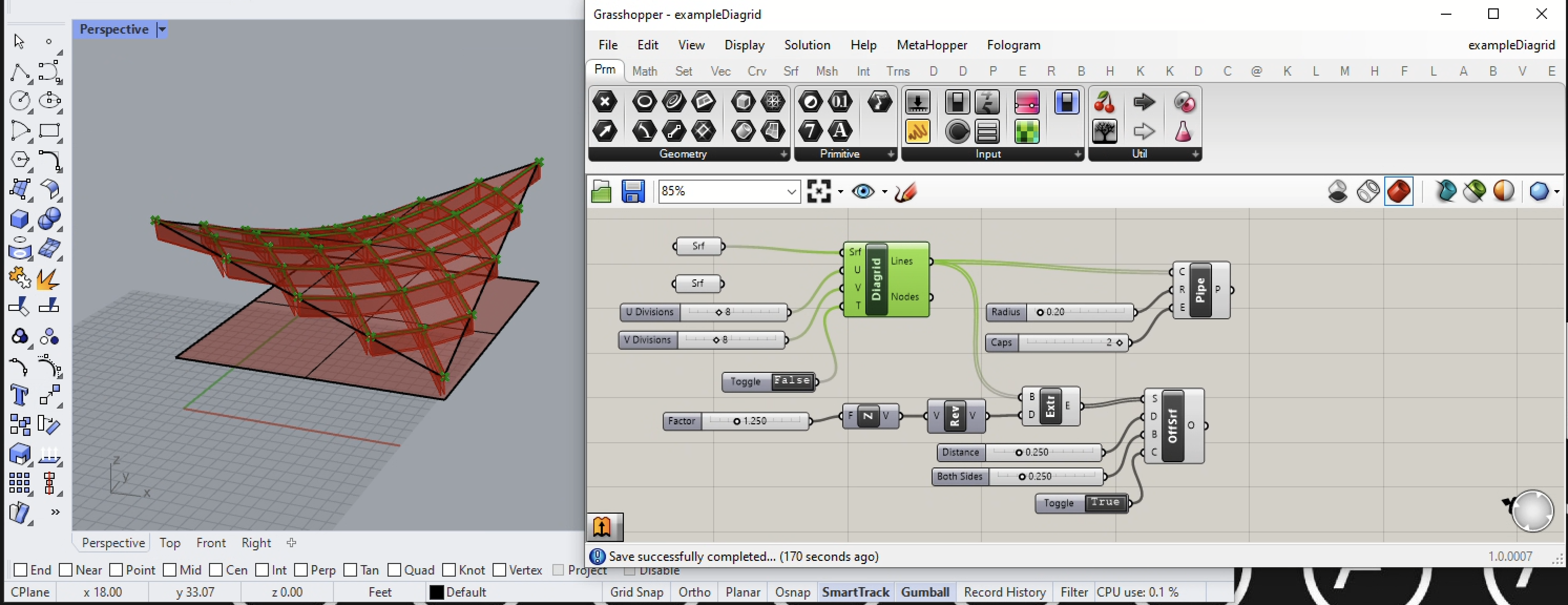
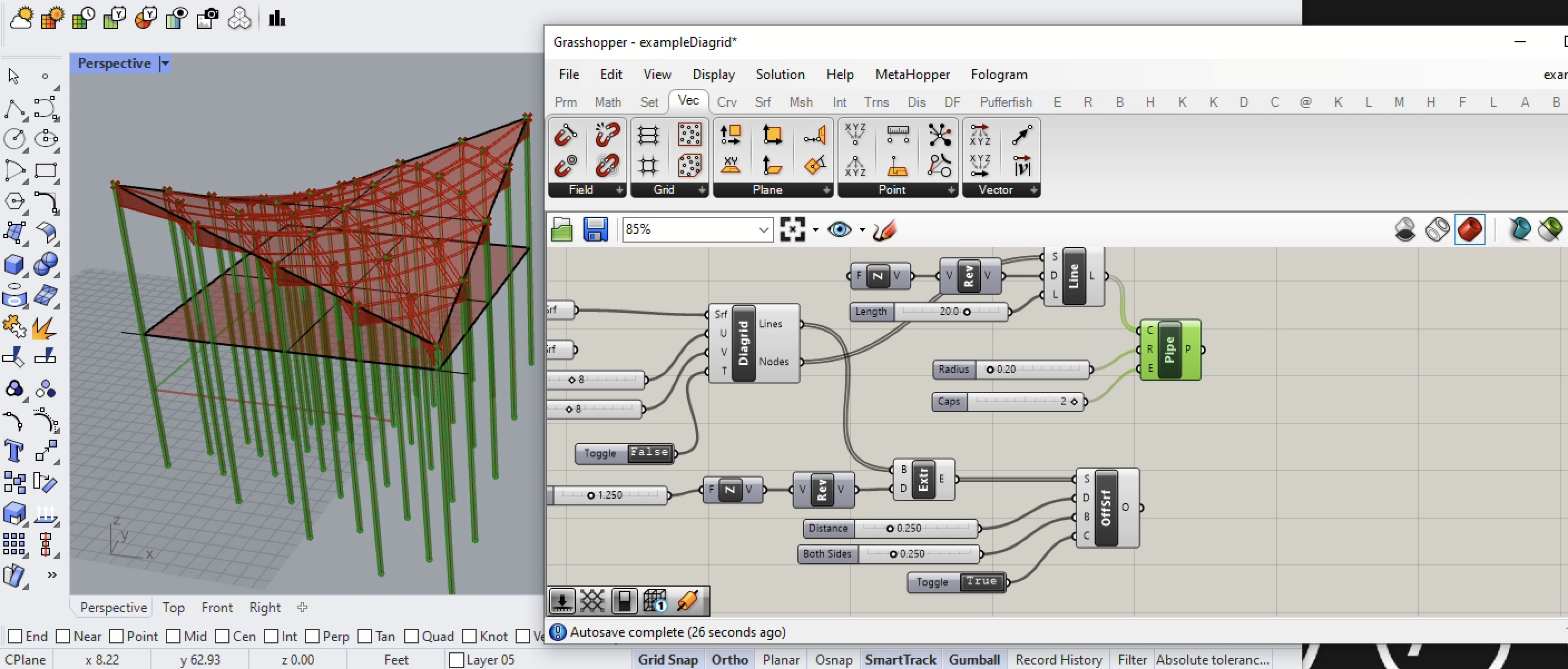
1. Using the same saddle shape surface, in this example we return to the Lunch Box plugin and add a Diagrid Structure as shown in the image below. If we take the output of the Lines port from the Diagrid component and export it to the C input port of the Piple component, then we can more easily see the diagrid lines (note that we will disconnect the diagrid from the Pipe component later in this example). This follows a very similar strategy to examples 1 and 2.
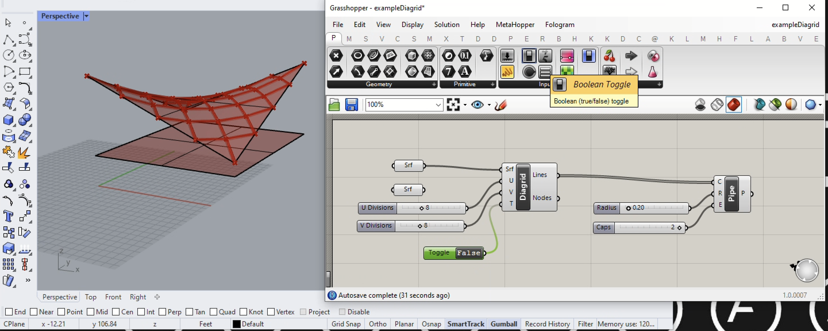
2. Here we begin to go further from the first two examples. From the Grasshopper Param tab, add a Boolean Toggle component as input to the T input port of the Diagrid component. Set the value of the Toggle component to False and note that the diagrad now intersects with the corners of the saddle shape.
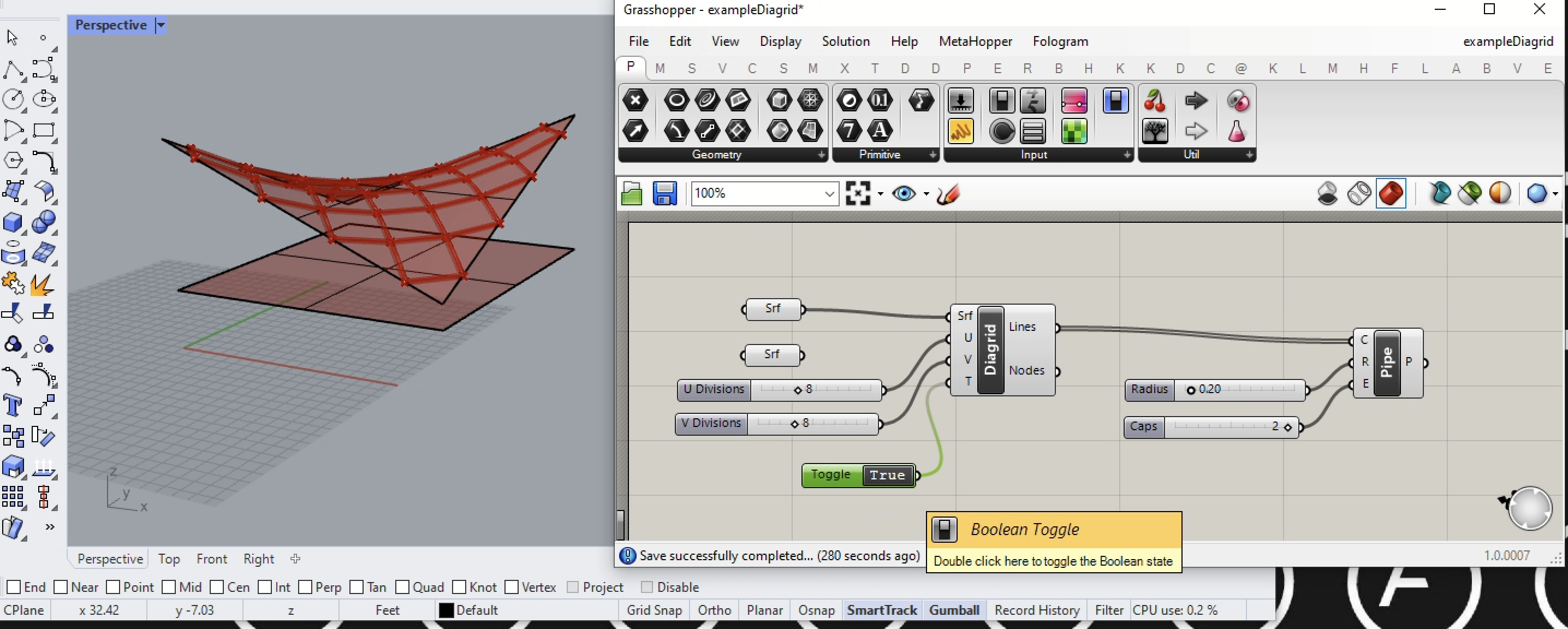
3. Set the value of the toggle to "True" and diagrid shifts such that it no longer intersects with the corners of the saddle surface.
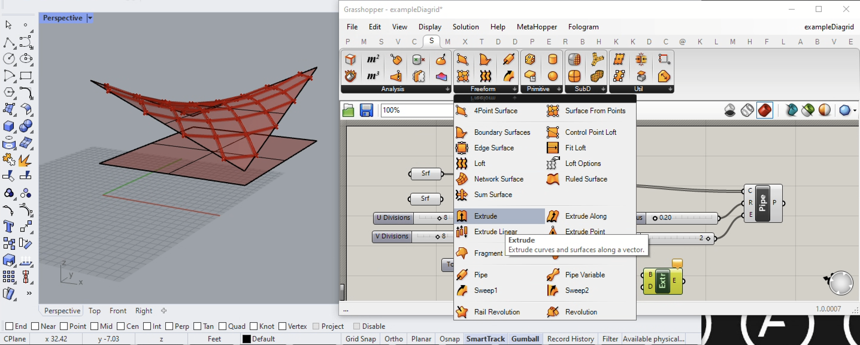
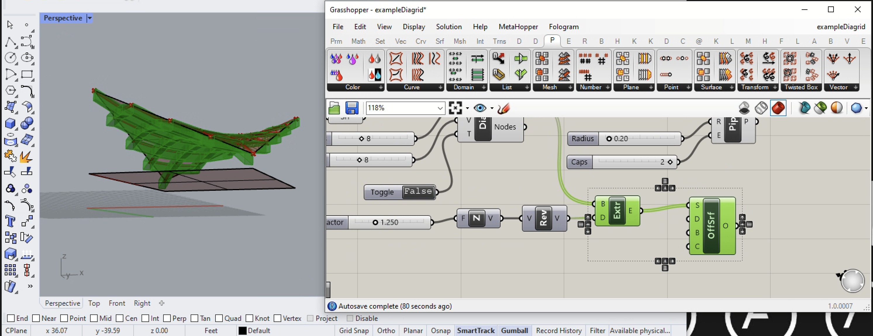
4. In this step we extrude the lines within the diagrid vertically. We begin by going to the Surface tab within grasshopper and adding an Extrude along a vector compoenent.
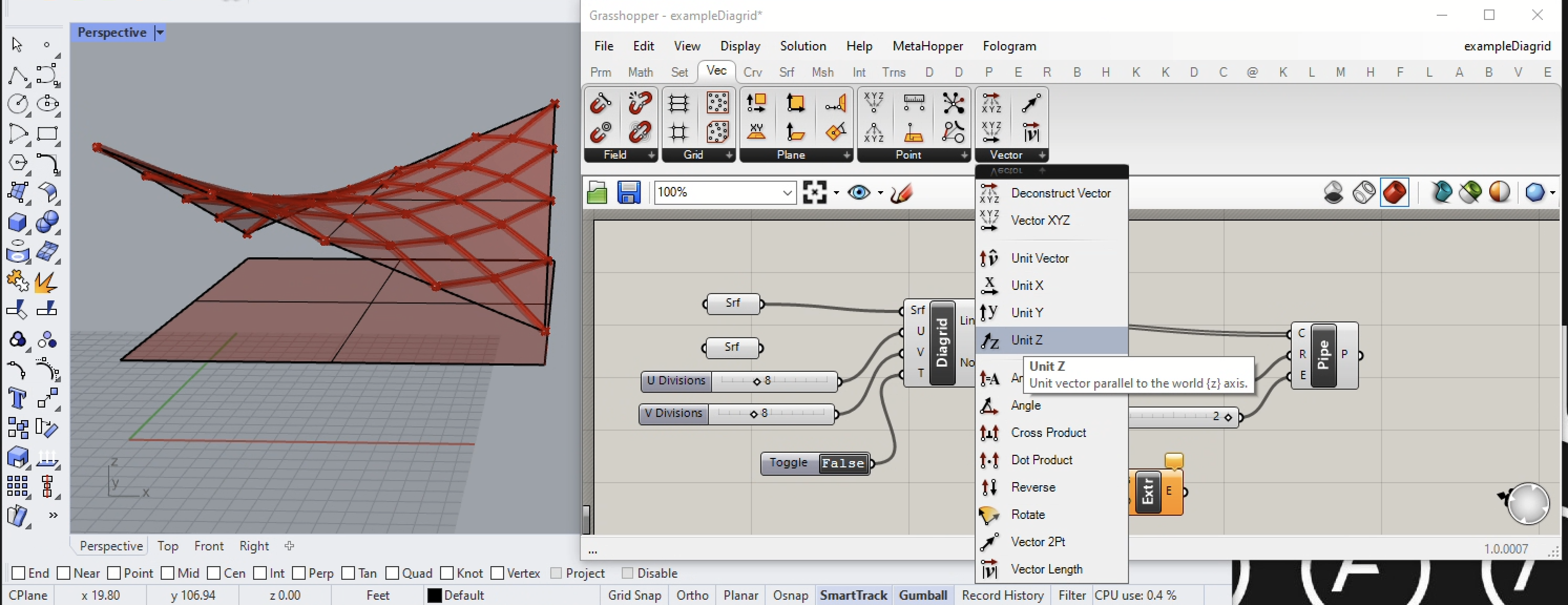
5. In the next step, we set the Boolean Toggle back to False so that the diagrid intersects with the corners of the Saddle shaped surface. We then go to the Vec tab and add a Unit Z component to the Grasshopper canvas window.
6. Connect the output of the Lines output port of the Diagrid component to the input port B (brep) of the Extrude component, and you wil discover the surfaces extrude upward a distance of 1 foot in this example.
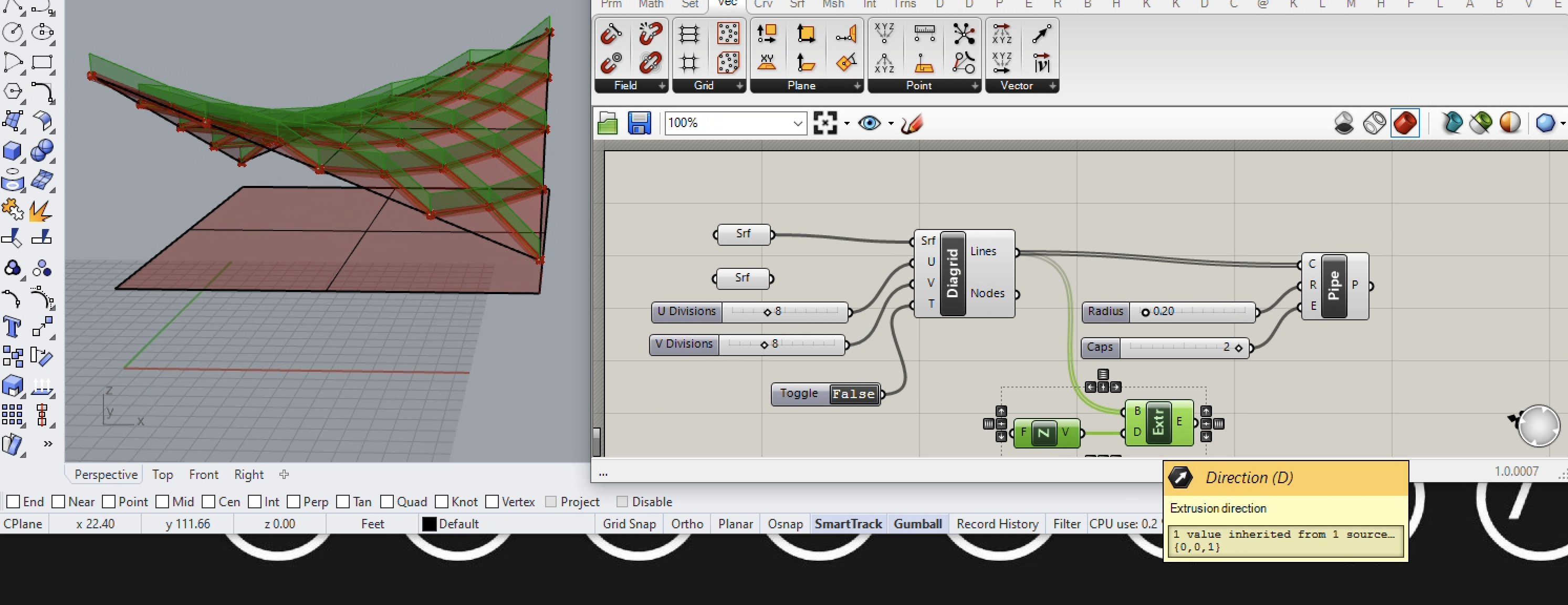
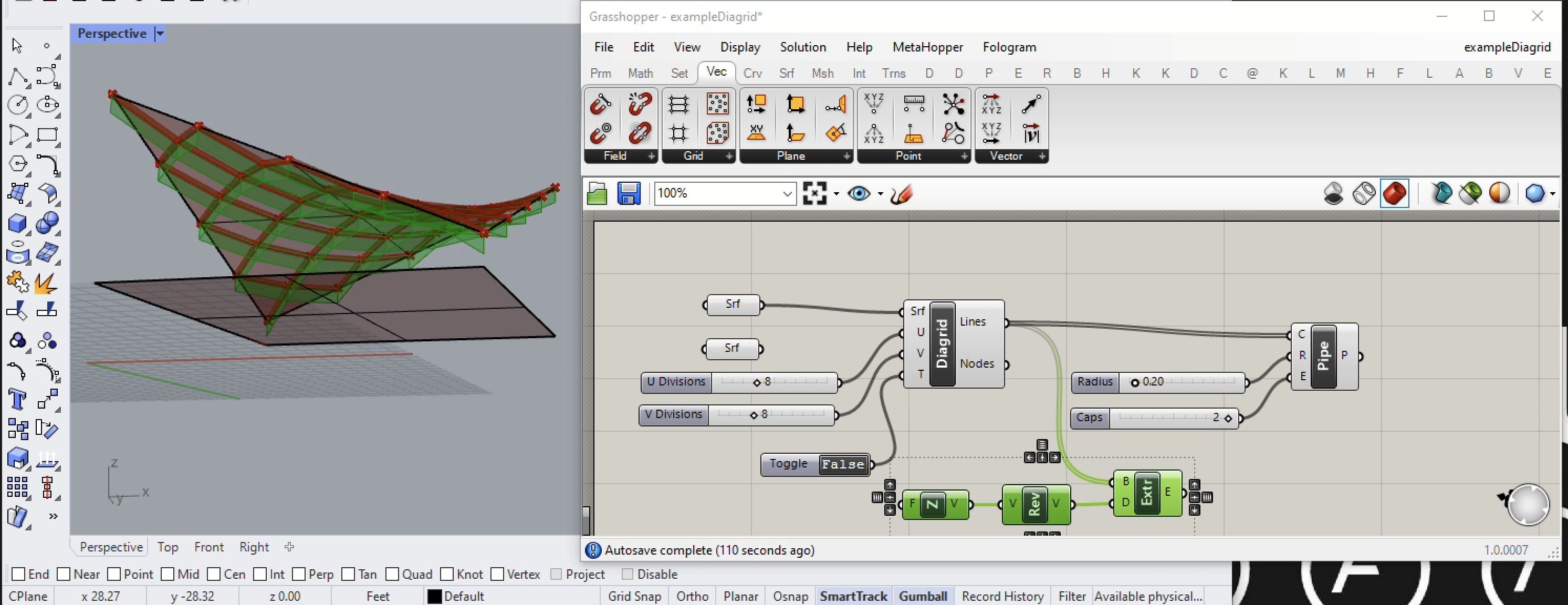
7. From the same Vector menu, add a Reverse Vector component and the extrusion goes below the saddle surface as viewed from a low angle in the image below. Note that the vector projection here is an approximation and slightly incorrect in that it should actually be downward from the saddle surface normal rather than in the negative Z direction. Fortunately, this can found with the use of additional Grasshopper surface components that can determine the surface normal at any location. However, this would complicate this present tutorial and so is covered elsewhere in other workshop notes. For example, see the saddle roof example at the end of workshop notes 5.
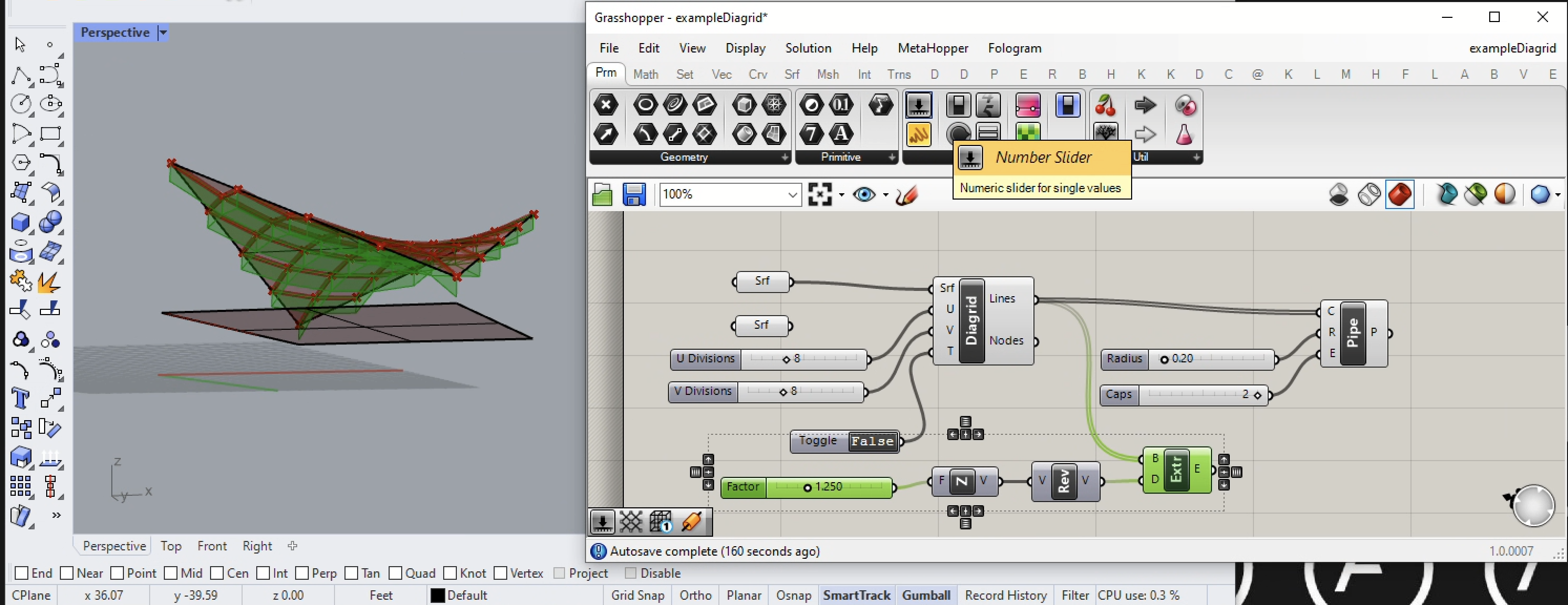
8.Next, add Number Slider input factor to the F input port of the UnitZ vector component to control the height of the extrusion (1.25 feet in the example below).
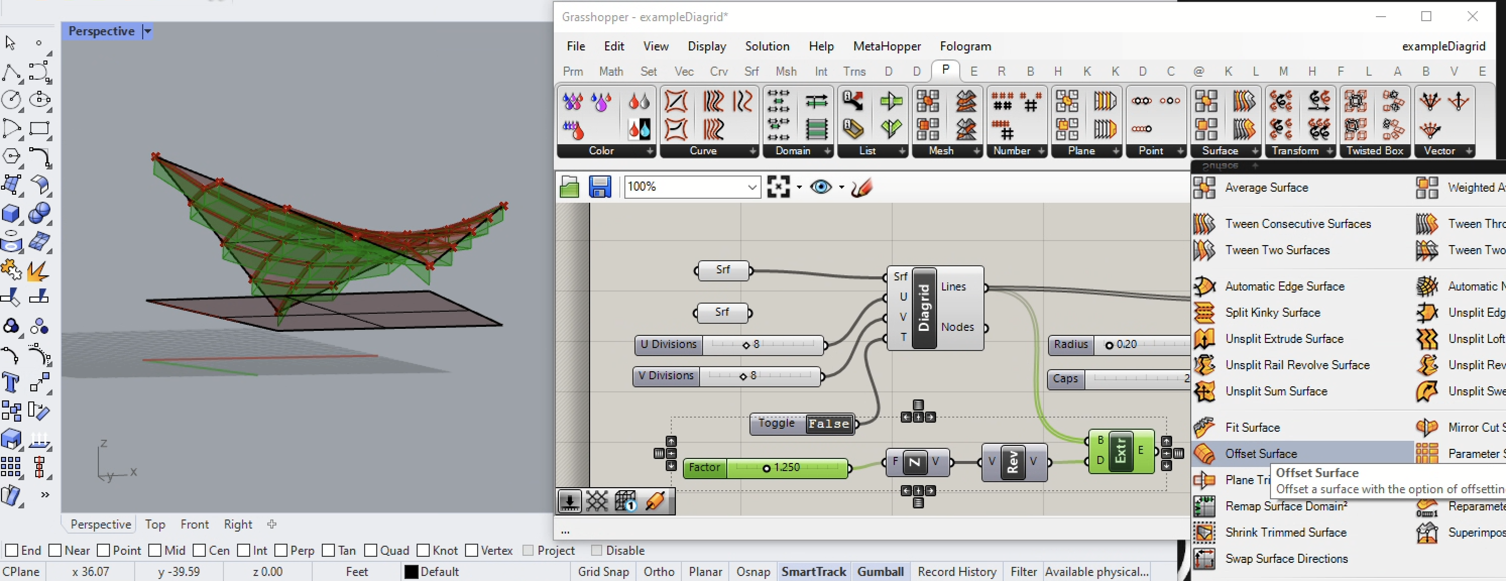
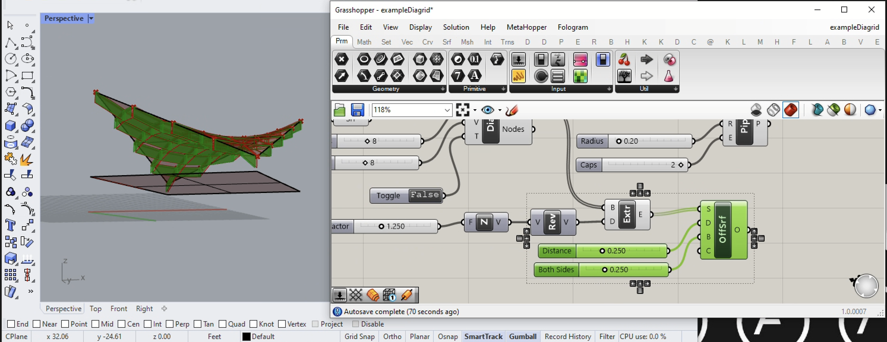
9. From the Pufferfish Plugin to Grasshopper add an Offset Surface component.
10. Connect the E output port of the Extrude component to the S (surface) input port of the Offsrf component. Note that the surfaces below the saddle surface now now offset horizontally in a single direction for a default solid object distance of 1 foot.
11. In the next step, however, we add a Number Slider to each of the D and B input ports that control the extrusion of the surface in two horizontal directions.
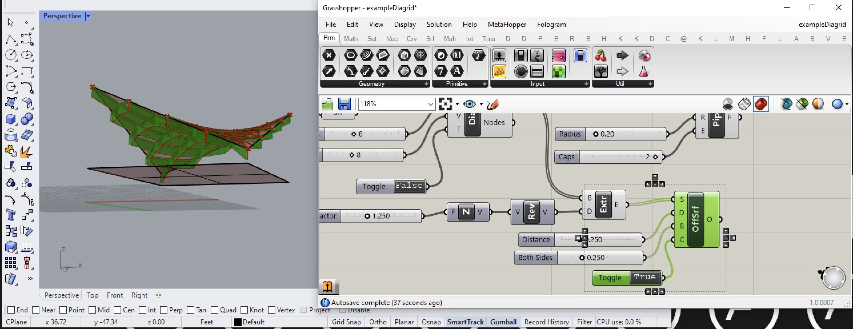
12. Next add a Boolean Toggle component to the C input porf of the Offsrf component. The toggle switches the offset from being either "True" (creates a solid shape) ir "False" (creates a non-solid planar surface on either side of the original vertically extruded surface. In the image below, the Boolean Toggle is sert to "True" to create the solid geometry.
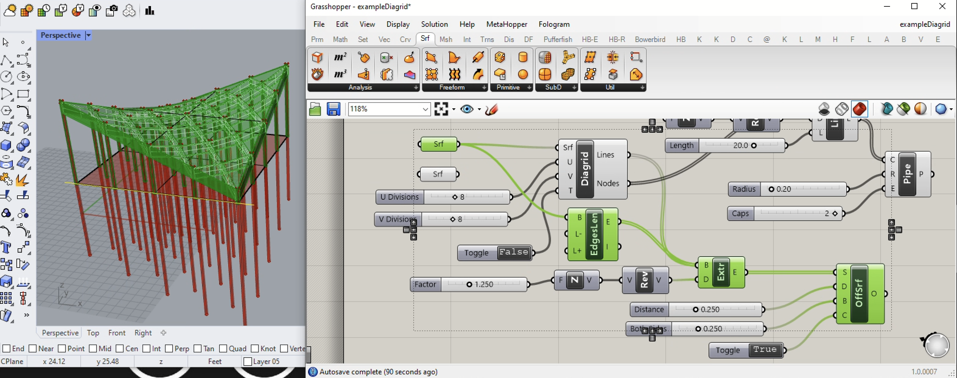
14. We next examine the Nodes output port of the Diagrid to create a set of columns below the roof/. These are the green vertices in the diagrid shown at left in the image below.
15. In the next step we open the Grasshopper Crv tab and we add an Line SDL component to the Grasshopper canvas window.
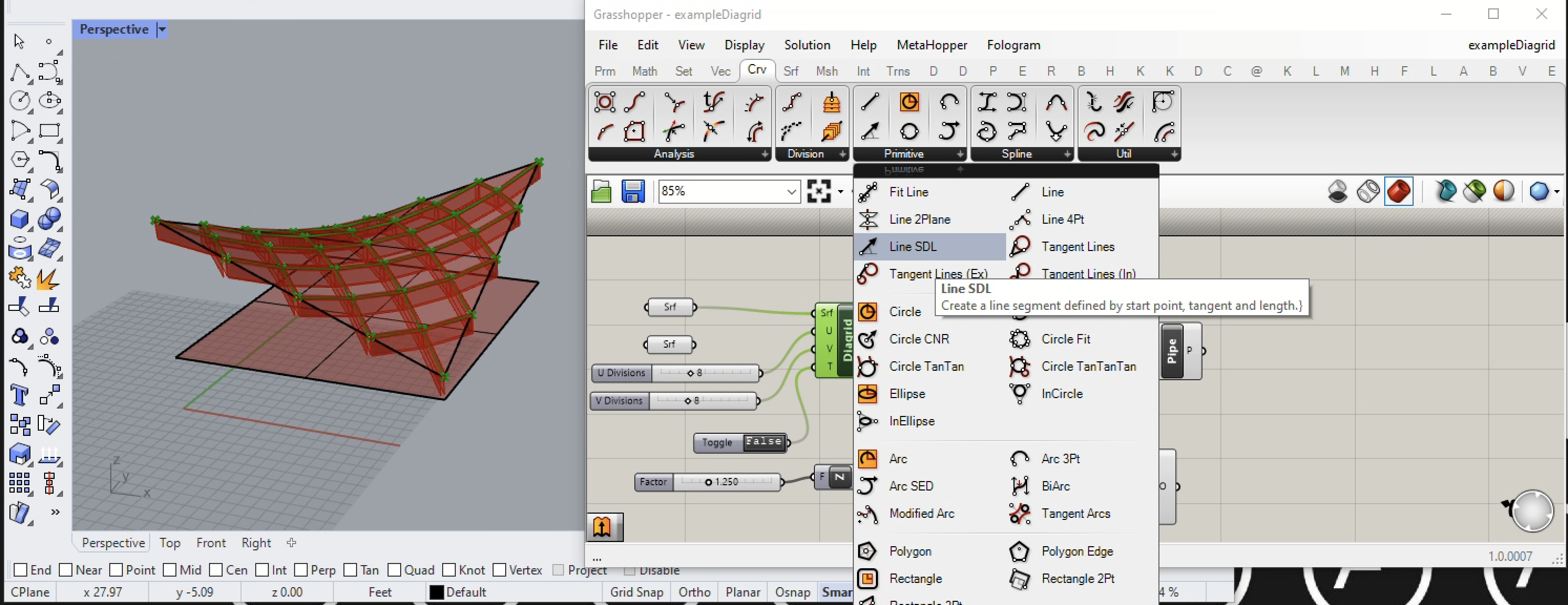
16. Connect the Node output port of the Diagrid component to the S input port of the Line SDL component. The result is that a default line points upward 1 foot at each node.
17. In the next step we add the combination of a unitZ vector and a reverse Vector into input port D of the Line SDL component . We also Number Slider into input port L of the Line SDL component. Using the slider the direction of the line is reversed to a length of length 20 ft below each node of the diagrid.
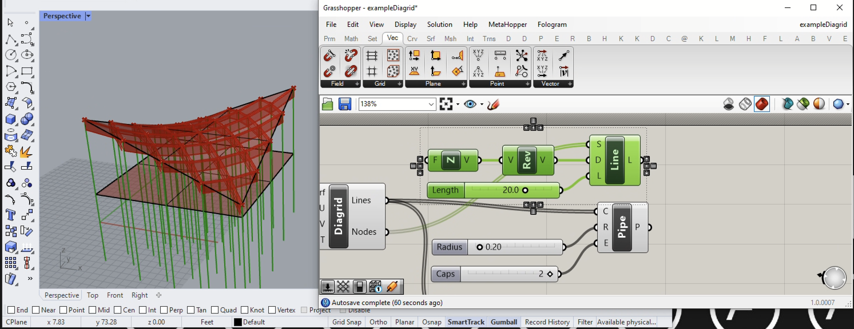
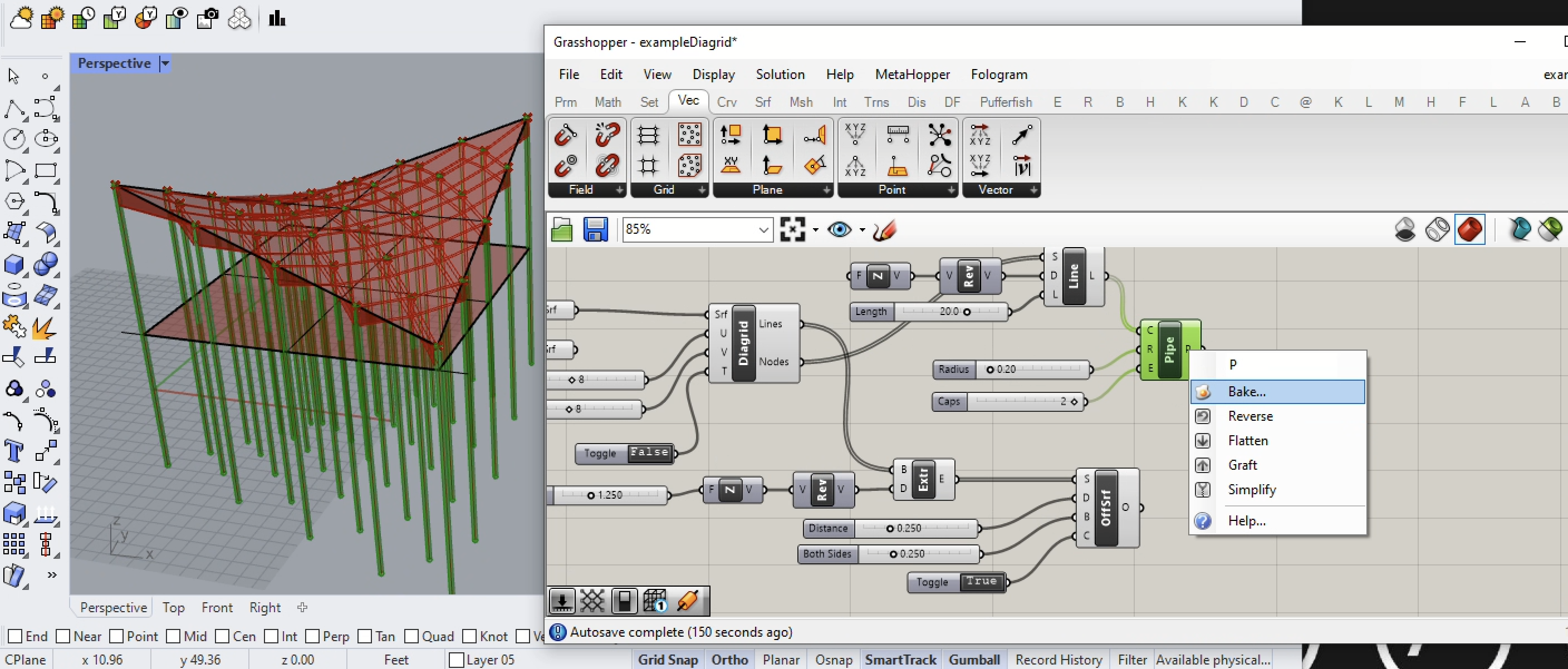
19. The extended lines below the surface are exported from the L output port of the Line SDL componentt and added to the C input port of the Pipe component (see arrow in the canvas window below). In this step we will also intentionally displace the lines exported from the Lines output port of the Diagrid component and imported into the input port of the Pipe component.
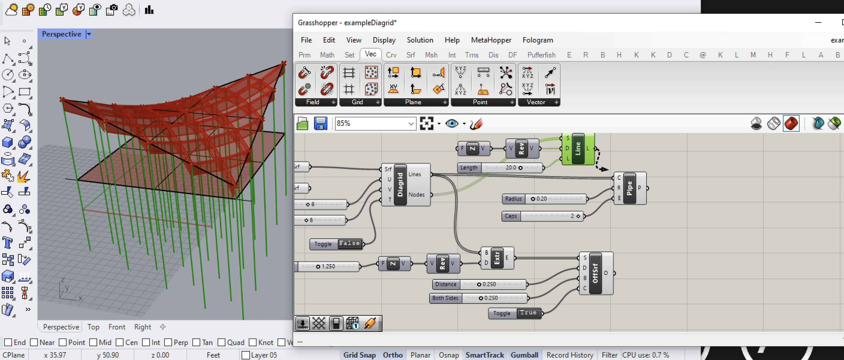
20. The vertical lines below the saddle shape turn into pipe surfaces. In addition, thediagrid formation of pipes in within the saddle surface ihave been displaced in the previous step are no longer visible.
20. In this step the verticle Pipes are baked into Rhino.
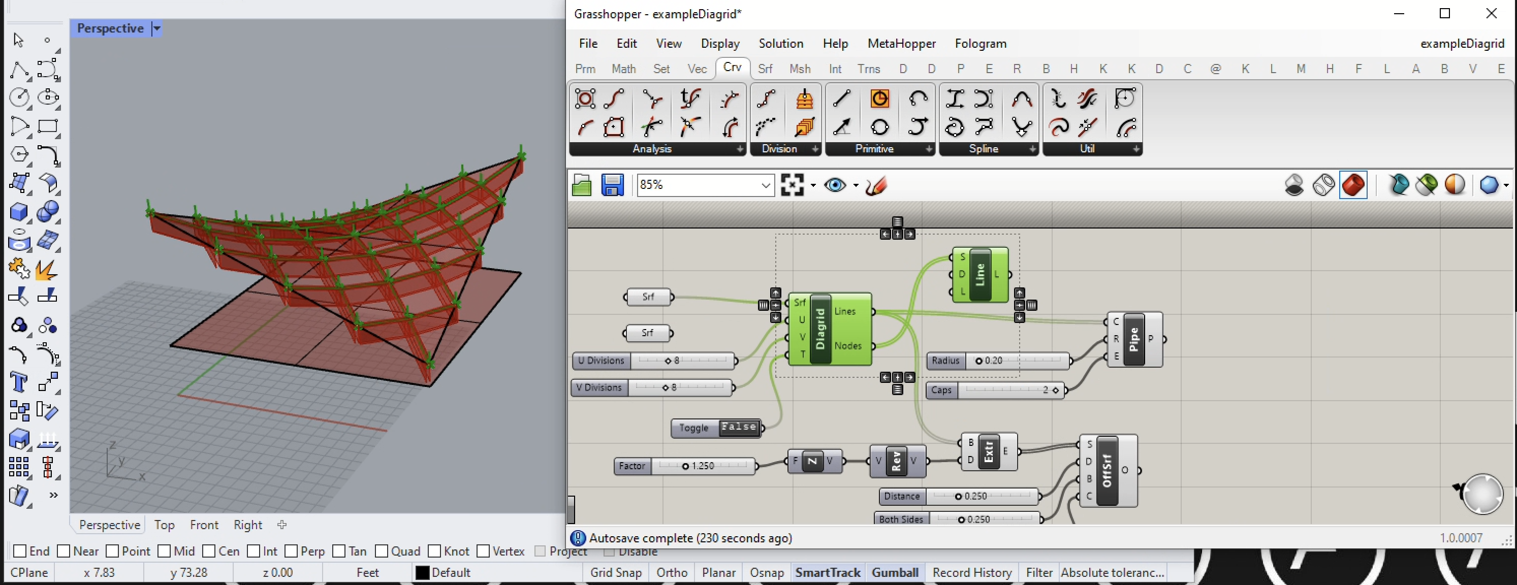
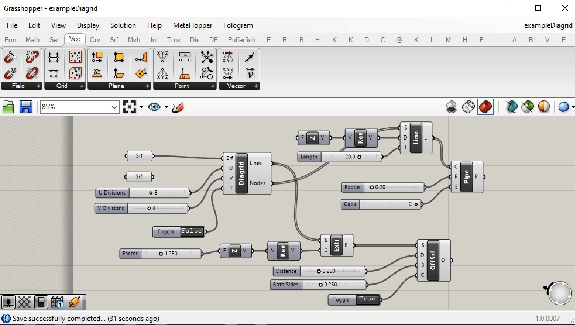
21. The Grasshopper canvas window whole at this stage is shown in the image below.
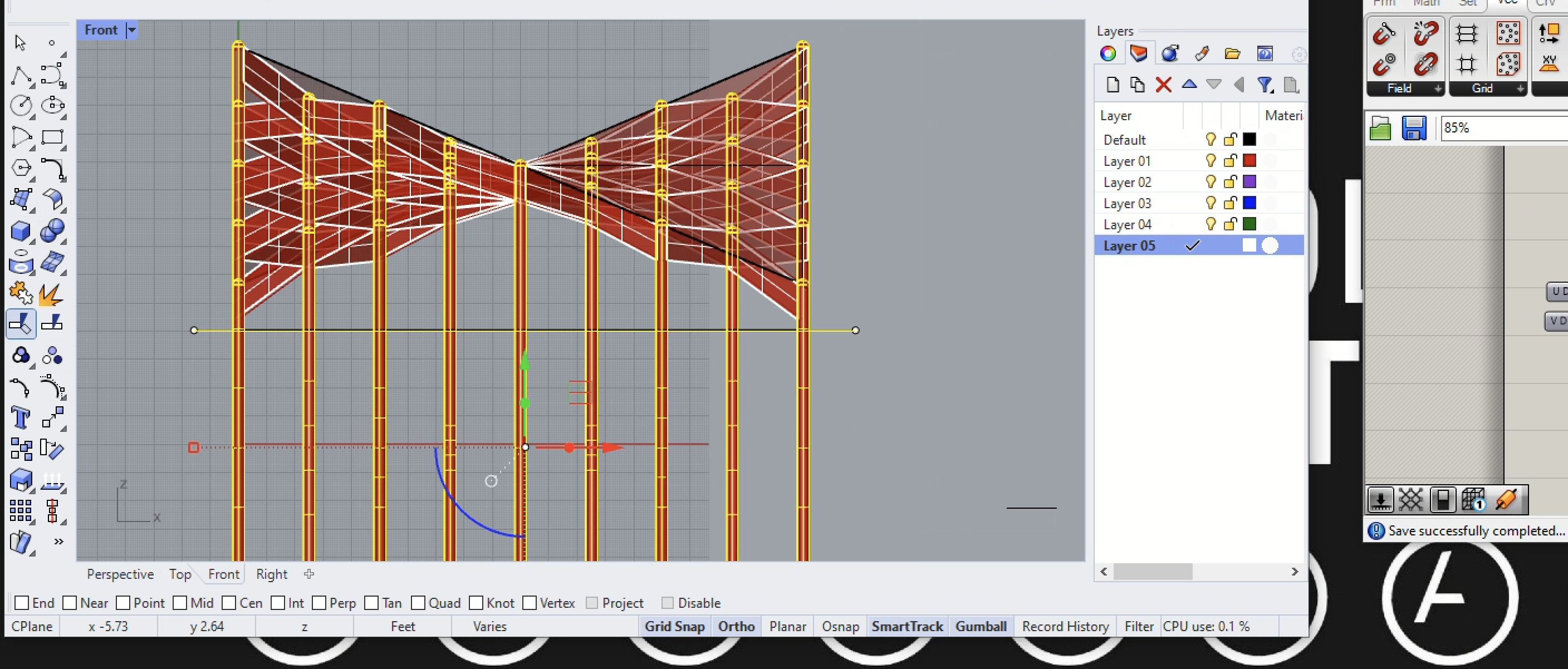
22. In the front view, the lower portion of the the pipes are trimmed using the Trim tool in Rhino (not Grasshopper). A horizontal line accross the middle of the front view is used trim the bottom of the bottom portion of the pipe surfaces.
23. The edges of the saddle shape roof also can be used to create the perimeter of the understructure. Begin this last stage by going to the Surface tab and Util subtab in Grasshopper and add the Edges from Length component as indicatged in the image below.
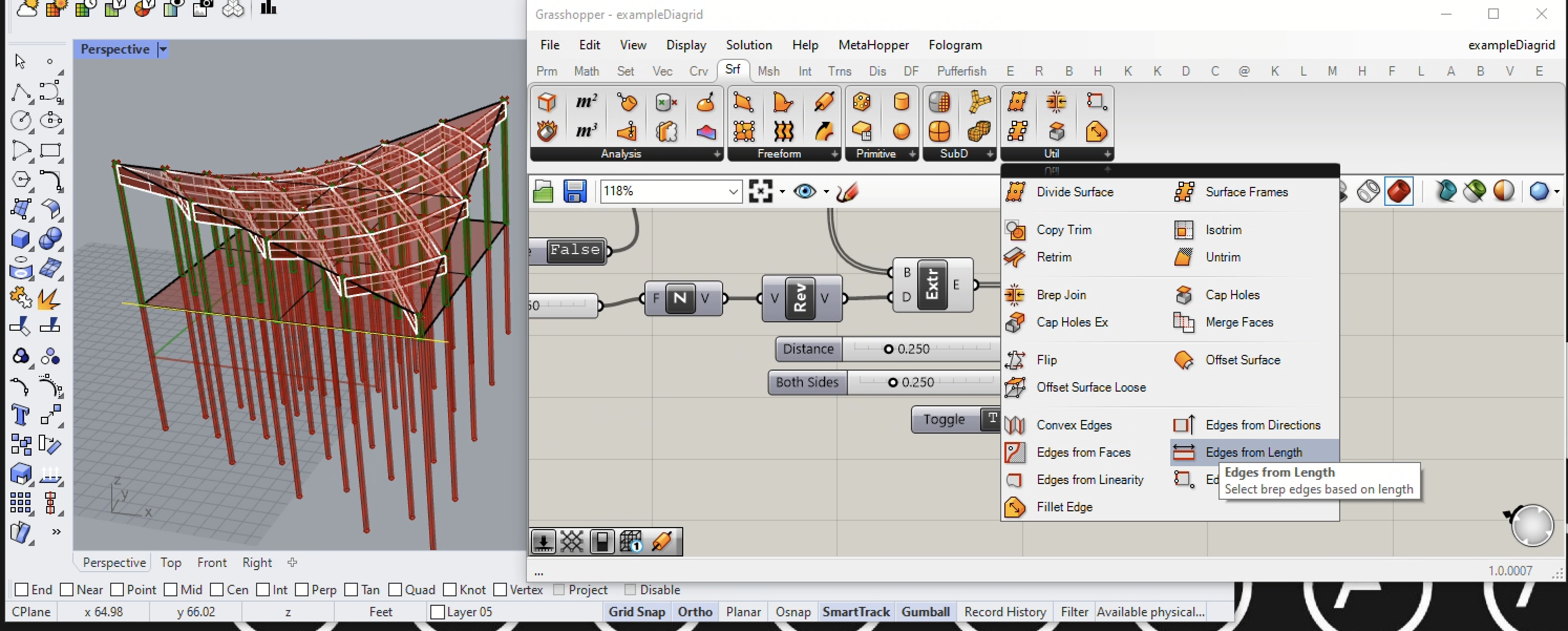
24. We next connect the saddle surface component in the Grasshopper window to the input B port of the Edges from Length component. In turn we connect the Edges from Length component to the Extr (extrude) component and the permiter of the structure under the saddle shape is thereby generated. Note here that we've realized an advantage in plugging the Edges from Length component into an existing process we had already established with components we created earlierin this Grasshopper canvas window. We are in a sense piggy backing on the earlier effort.
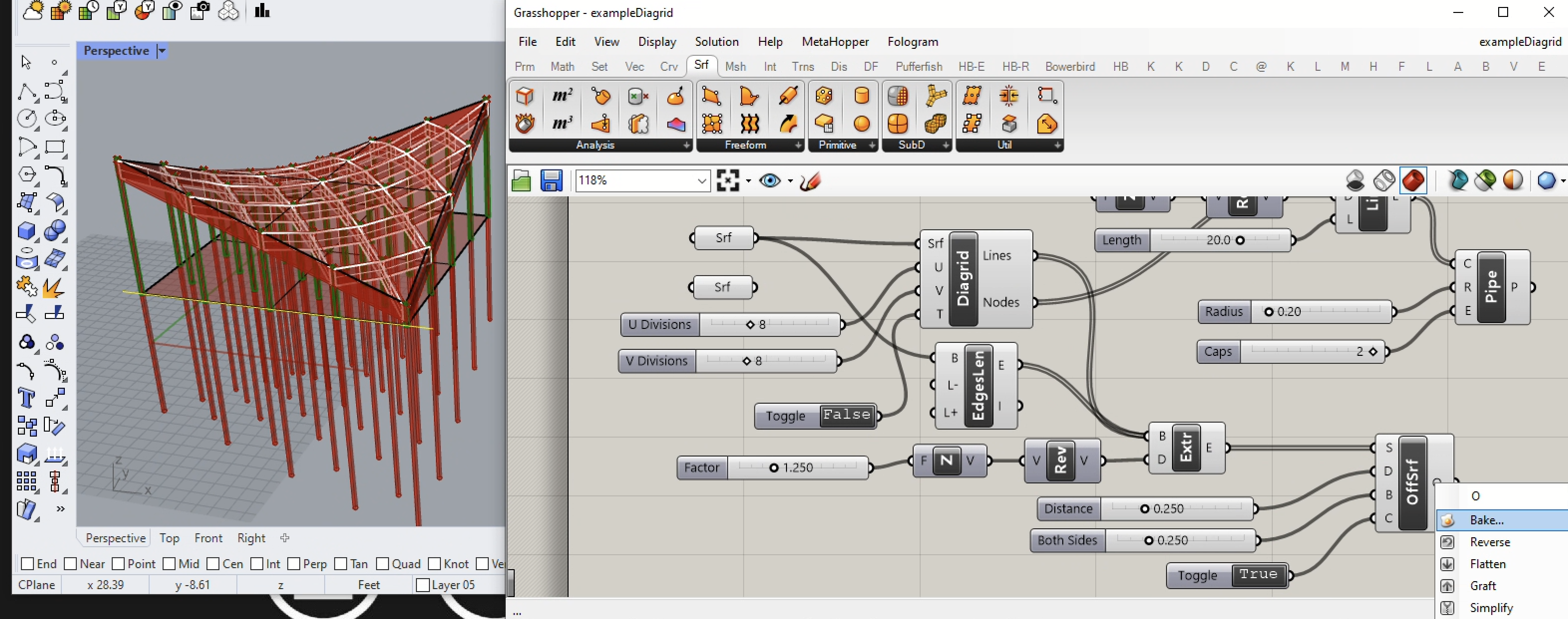
25. Now all the offset surfaces are baked into Rhino.
26. Note that a preview rendering indicates the there's a problem with the understructure penetrating the saddle roof.
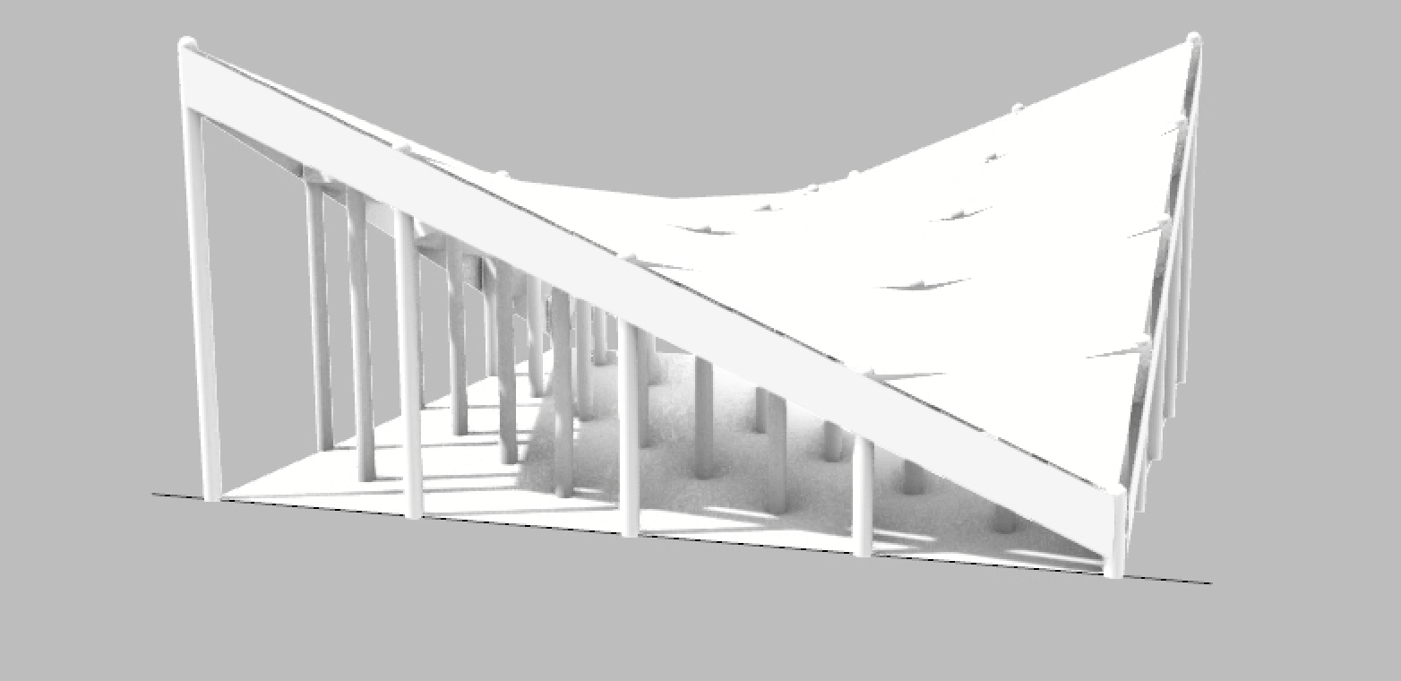
27. Here we simply extrude the roof surface upward to visually avoid the issue. A more complete and correct solution is beyond the scope of this tutorial.