![]()
Workshop Notes
30 September 2003
Triforma Solid Modeling Wall Command Utilities and Perspective Rendering
Architectural Solids: Domain within Microstation Triforma
Intelligent 3D Modeling Elements (walls, windows)
Semantic Knowledge: Pieces know about their application world
Microstation >Triforma >Bentley >Architecture
1. Construct Wall
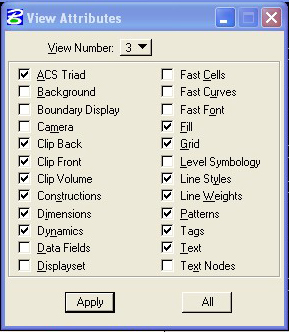
Shut down all windows except window view 3 (isometric view)
Maximize View
Turn off Perspective Settings, Camera, Off
Find Triforma Primary Toolbox
Place Wall Tool (third down on right) pull out toolbar
Do not touch wall types, use default interior partition wall
Click off "by part" toggle boxes
Specify a Height and a Width
Icon indicating how wall is drawn
Draw wall along middle of the wall
Draw wall along left of wall
Draw wall along right of wall
Click once in View 3, Click T of top construction plan, click once again to specifiy the wall distance. Then click right mouse once to verify selection
You continue wall by simply continue left click before you accept with your right click
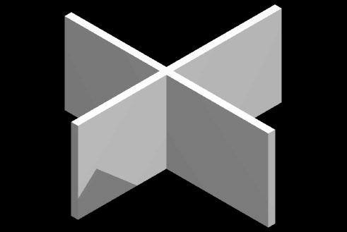
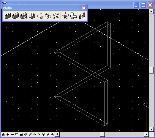
2. Draw Intersecting Walls--Construction Process:
Draw a single length wall.
Draw a second wall intersecting the first at a perpendicular (a cross in plan)
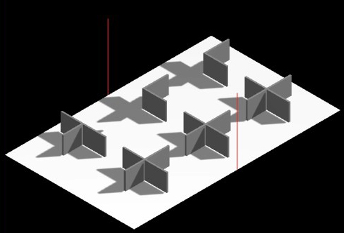
3. Copy Intersecting Walls
Change to Top View (Click on the dynamic Display and Select Top)
Preselect your two walls with the arrow key (draw a box around the walls)
Select the copy tool and copy your two walls into two rows of three
Still in plan view: draw a rectangle that completely encompasses your walls
Switch back to the isometric view
Render your model (tools>visualization tools)
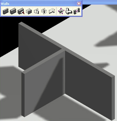
4. Control Walls by Various Join Operations
Return to Triforma Pallette
In Edit Walls Palette, Select the Second Tool from right hand end
Four Options to join/intersect walls:
T intersection
Click once on secondary wall (to be cut)
Click once on dominant wall
Click once on right to confirm
L intersection with one wall dominant
Click on secondary wall
Click on dominant wall
Click once on right to accept
Mitered Intersection
Click once on each wall
Click once to accept
Cross Shaped
Click once on Dominant wall
Click once on Secondary wall
Right click once
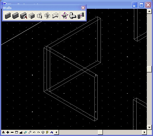
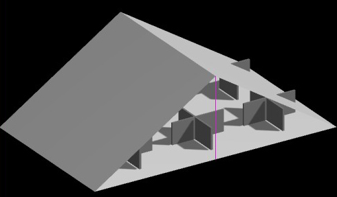
5. Build a shed roof above set of walls
Turn off ACS plan snap and ACS plane locks (lower right corner of Microstation window under lock icon)
Select the Smartline tool
Draw a Rectangle
Tentatively Snap onto midpoint of rectangle that you drew earlier
Accept the point you snapped by left clicking once
Hit "F" key to rotate accudraw into front view
Draw a line vertically, clicking once to initialize line and again to identify height (Right click to accept point)
Copy the Line you drew to the opposite site
Grab line with a tentative, confirm it, select opposite side midpoint and confirm it
Make Sure no Lock is on within Accudraw
Select the Smartline tool and draw a line from the top of your vertical line to the lower corner of the previously drawn rectangle, continue drawing the line segment to create a CLOSED POLYGON LINE as one side of a gabled roof
Repeat this step to draw the other side of the Gable as a closed polygon
Make sure you snap to each corner precisely
Render your drawing to make sure you successfully closed your polygon line
6. Project Walls to Roof
In walls tool palette, third icon from the right end>Modify Form tool
Change the method over to "to shape"
Select the first icon in the Modify form tool
Grab the first roof edge (it will highlight)
Grab the second roof shape
Move the mouse away from geometry and click once on right mouse button to confirm the elements you will extend to
Click the left mouse once to initialize your wall selection that you wish to extend
Click on each wall segment, and the walls should extend themselves up to under the gabled roof line.
7. Using the same Modify Form Tool
Change Method within tool box to "add distance"
Select "relative" mode
Type in the intended extension length
Click once on the wall and the wall will get longer by the entered amount
Can also modify the width, the height, and the length of the wall
8. Prepare to Manipulate Perspective Viewing
Open View window one and View window three
Tile the two windows (window>tile)
Fit View in Both Open windows
9. Rough Perspective Viewing Tool
Set View Depth
Tools> View Control
Select Set Active Depth Tool
Pick View window you want this to apply (view 3)
In Plan View , Click once on the Front Plan of your Gabled Roof to identify Depth
Choose the Perspective viewing icon
Click in the middle of the view window and hold down
Drag the mouse down diagonally to the bottom left of the window.
The view pulls into perspective, while holding the active depth constantly
This perspective is 3 point perspective, giving you significant distortion
10. More Precise Perspective Control
Setting >Camera >Off
Change View back to Front elevation view
Tools>visualization>Rendering
Select Define Camera Icon (third from the left)
Select the View you wish to manipulate (view 3)
Make Sure Continuous View updates and Display View Cone are both toggled on
Camera Action >dolly
Projection>Two Point
Move around View by manipulating the View Cone Points
Other Options in View control
Roll- camera rolls around a point
Pan- pans across model
Lens Focal Length- allows you to change between telephoto and wide angle focal lengths
[Architectural Convention is to use two point perspective to assure that all vertical lines remain parallel]
11. Cut a Section in your Model
Under Define Camera>more
Go to display depth
Allows you to clip your model in section, based on a specific distance from where your camera's station point is located (camera's location within space)
As you dolly up closer to your model, the model cuts away at the specified distance
12. Additional Camera Control
Settings>Camera>Lens (change focal length, view cone angle
Settings>Camera>Off (return to isometric view)