![]()
Workshop Notes
Workshop 9
4 November 2003
PARTICLE TRACING
http://archweb.arch.virginia.edu/~ejm9k/arch541/Handouts/render/ptrace.html
Part I: Particle Tracing Setup
- copy directory
arch541/read/ptrace
- go to utilities >
saved views: apply pers1
(perspective without walls)
- tools >
visualizations > rendering
![]()
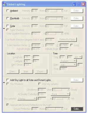
- global lighting (sun
icon): turn off
ambient/flashbulb/solar lights for particle tracing.
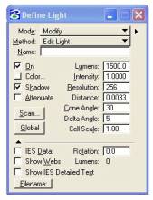
- define light (light
bulb icon): see lights listed and
values; lumens: light energy
rendered in particle tracing.
- settings/view
attributes/constructions on … see two point/two spot lights.
- settings/view
attributes/constructions off … be sure to turn off constructions prior to
rendering.
- tools >
visualizations > query illumination (cube w/ question mark icon): gives a continuous reading of energy
output.
Part
II: Particle Tracing Settings
Interface
> Show Advanced Settings – shows the extended Dialog Box for Particle
Tracing
1. Action
- current, new, augmented solutions; Create a new solution each time you change
the lighting conditions in the model.
2. Particles
Settings - number of particles to shoot (begin 1 mil)
3. Maxmium
Bounces - number of times to bounce each particle (avg 100)
4. Illuminate
Both Sides - Turn off if non-illuminated surfaces are not to be rendered
(typically on)
5. Ray
Trace Direct Illumination - Alleviates mulitple shadows computiung shadows
from light sources not reflected light - (typically off as disrupts realism)
6. Mesh
Settings - Smooth, smaller values produce sharper shadows, but can
introduce noise. Higher values produce
smoother shadows, but can be blurry if value too high.
7. Mesh
Detail - resolution of rendering mesh, higher values produce more accurate
results at greater cost in computational time.
8. Minimum
Mesh Detail - in Master Units, specifies minimum size of smallest feature
visible in solution (typically leave this off)
9. Display
Mode- Renders result either in photorealistic image (raytrace),
illuminance (energy hitting surface
“incoming”) or luminance (energy
reflecting from surface).
10.
Brightness Multiplier – Changes the aperature of the camera to receive
more or less light. This setting does
not change the light definitions.
|
|
|
Example:
Action:
create new solution
Use
1 million particles
Max
bounces: 1 million
Illuminate
both side surfaces
Ray
trace direct illumination (off)
Material
Receives/Reflects light (always)
Meshing
settings (Smoothness 3, Detail 3)
Min
mesh spacing (off)
Display
mode: visual/color
Raytrace
final display (on)
Wiremesh
overlay (off)
Brighness
multiplier (as is)
RENDER
Change display mode to luminance and then
illuminance.
Action: Display current solution
RENDER.
Change lights:
Add sunlight on.
Action:
Create new solution for each new lighting condition.
RENDER.
Change Brightness multiplier:
Lower Brightness multiplier: (0.16)
Sample hot spot – alt option.
RENDER.
Add background image (doesn’t really effect energy
solution)
Action:
display current solution
RENDER.
Save solution (ptd particle trace solution file)
Reload solution.
Part III: Define Light/IES Data
Allows
the import of photometry data from lighting manufacturers.
http://www.lighting-inc.com/searchman.html
IES
Data will only work with point lights.
Show
webs: shows the distribution of light
for a given light fixture.
Example:
Download from classes: iesex/testies.dgn
Use 75rries.ies {Lightolier/12” handing
pendent/incandescent.
With
two point source lights/ and 0755FR.IES and 0584FR.IES data sets for 12”
pendentive and 12”pendentive with aluminum reflector - 150 Watt bulbs.
Load shp file … Do current particle trace solution or
make new one.
Adapt to brightness as necessary
See also lamps.html in same directory.
Part IV: Overall Concepts
Question
1: How do I get a "good" particle Trace solution?
Answer: There are several different ways to achieve better
results when we Particle Trace render. Below are a few ways to accomplish this.
* Step
1 - Raytrace
First
thing to do is open the rendering tools, and render the scene using Raytrace to
see what the scene looks like currently, but be sure to turn off ambient and
flashbulb lighting. If the scene does not look good in Raytrace, then chances
are they are not going to look good in a Particle Trace solution. It may be too
dark, then we need to address the lighting by adding more natural light. If the
scene is brighter than desired, then the lights need to lessen by lowering the
intensity. So when the scene looks well lit and everything is in clear view.
* Step
2 - Particle setup
Use
the default settings first, to see what you get.
1. 1 million particles
2. Mesh smoothness on 3
3. Check off "RayTrace Final
Display" so we can see the results faster.
To
speed up the process is to check on "Raytrace Direct illumination" in
the Particle Trace setting dialog box. With this setting checked on, the
raytracer will compute the shadows from the light source, but not the reflected
light.
* Step
3 - Brightness
The
first rendering may appear darker than the Previous Raytrace rendering. This
can be fixed by adjusting the brightness multiplier.
* Step
4 - AMP (Add More Particles)
Add
more particles if:
1. There is tiling or faceted elements
then more particles are needed. Some edges can not be smoothed if the angle is
too sharp.
2. There is color blotches randomly in the
scene.
Try
bumping it up to 5 million particles in the scene, but to do this efficiently,
change the Action setting to "Add more particles and redo mesh" and
set the particles to 4 million. Since there is already 1 million particles in
the scene, adding 4 million more will give an even total of 5 million.
It
may look better, but it may not look good enough. Adding more particles is the
best way to get the scene looking better. If some elements do not smooth out
then they probably will never smooth out enough. This is related to how the
element was modeled. If the angles of the edges are too sharp it will be able
to be smoothed out. It is like trying to smooth out a cube. Thus this is the best
it will get.
* Step
5 - Mesh smoothing To change the mesh settings, which will create more
detail, first you need to click the Redo Mesh button, since you are not adding
particles; you do not need to recalculate the shooting of the particles.
Setting the smoothness setting to a lower value such as 1, the rendering, will
be less detailed and the particles will spaced further apart, which can produce
the colored spots. This is because the mesh is not as detailed and will not
except as many particles; hence the colors become blotchy. So the default
setting of 3 may be good enough.
* Step
6 - Final touches Once you are satisfied with the detail of the solution
you can display the final rendering for the view by going to the Particle Trace
settings and selecting "Ray Trace Final Display" then selecting
"Redisplay Solution and select the view to render the scene for a final
rendering. This will combine the Particle Trace solution with a Raytrace
rendering. The Particle Trace solution is not a rendering solution on it own,
it is only a lighting solution. Raytracing the scene will display the
highlights and reflections of the elements in the scene. Not using "Ray
Trace Final display" speed the time for the rendering process. This helps
when you are only working on the Particle Tracing solution and not concerned
with the display of the highlights and reflections.
IES
Data: Manufacturers provide this data on spread and intensity of light that can
be substituted for lighting setup parameters. Should be used on point source
lights only.
Illumincating
Engineering Society (formed in 1906) (IESNA/IES) – Included Honory member
Thomas Edison.
Question
2: What settings values are recommended for the initial rendering?
Answer: Using the default settings is a good place to
start, they are:
* 1 Million Particles
* Mesh settings/Smoothness of 3
* Uncheck "Ray Trace Final
Display"
* Turn on "Ray Trace Direct
Illumination" in the Raytrace settings
Part
II: Notes on rendering setup
(rendering:general)
do for x:/Arch541f03/lec8/test.dgn
shadow
maps (see general ... leave off save shadow maps)
anti
aliasing grid side (draw pixels and diagonal lines)
grid
size
2
means 4 passes on a 2x2 grid
3
means 9 passes on a 9x9 grid
stroke
tolerance - maximum deviation of curve geometry from
true
pixel locations where all curves represented as polygons
how
many edges in polygon
shadow
tolerance - how close shadows are to cast shadows
prevents
from objects casting shadows on themselves,
higher
values means lower accuracy
shadow
filter size - softness of shadows , higher value means
softter
shadow (describes number of pixels to look at in the
shadow
map) ... too large means no shadows, too small means
objects
cast shadows that conceal themselves.