![]()
Workshop 2 Notes, Week of September 5, 2005
1. PRIMITIVES REVIEW
Primitives consist of basic elements such as lines, circles, arcs, boxes, etc.
Primitive tools typically have dialogue boxes associated with them to
control the method of primitive creation (ie. by edge, center,
diameter, copy, etc.). Remember to use these dialogue boxes to control the ways in which your tools are working.
2. TOOL BOX ORGANIZATION
![]()
![]()
Within the tool bar,
additional sub tools can be accessed by holding down any tool with a
triangle in the lower right hand corner.
These sub-tools can be pulled out and revealed as their own tool bar as well.
3. CURVES
![]()
Point or Stream Curve: [5th tool in the Linear Elements tools bar] This is a line based, simple curve that is very quick, but does not provide a lot of control or exact geometrical specification.
![]()
B-Spline Curves : [Tools Menu/ B-Spline Curves/ Create Curves]
Method: Control Pts, the curve is drawn by pts which effect the gravitational pull acting upon the curve.
Method: Through Pts, the curve is drawn by pts which are directly in the path
of the curve….more direct.
![]()
Bezier Curves : [Tools Menu/ B-Spline Curves/ Create Curves/ Composite Curve]
Mode: Bezier Curves, this curve is defined by tangential lines. Their length effects their impact on the curve.
NOTE: Don’t just trace the
drawings. Work to figure out the geometric rationale behind the design. This
will take you further towards a correct model and geometry (ie Helix tool
for the Guggenheim ![]() )
)
4. LEVELS (aka LAYERS in other programs)
![]()
Levels are created by either clicking on the level manager tool, or selecting level / manager / levels / new from the settings menu. Conventionally, each level in Microstation is given an independent color. To begin, create a new level for each different element of your drawing. Work this way in order to keep your drawings organized. It may be that you will adjust this system as your model develops.
![]()
The active level can be changed by selecting it in the level manager tool box.
5. ERASING LAYERS
[Settings Menu/ Level/ Manager] Highlight the layers you wish to delete. Press delete.
6. CHANGING THE COLOR SETTING OF A LEVEL
[Settings Menu/ Level/ Manager] Within the Level Manager, click on the box in the “Color” column next to the layer you wish to associate with a color. This will set the “by level” color of this level.
![]()
![]()
When you return to the main screen, ensure that the level creates this color by checking the “By Level”option in the Color Pull down menu at the top of the screen. Weights and Styles are managed similarly. All attributes can be modified by selecting elements (control click for multiple objects) and clicking in the upper left drop down box, and can be applied by level or object
7. MODIFY TOOLS
![]() Modify element. This very generic and useful tool can be used to alter a
primitive multiple ways, including: a point (by clicking on a point),
an edge (by clicking on a midpoint of a segment) or size of an element
(by clicking on a point of a circle, box, etc.).
Modify element. This very generic and useful tool can be used to alter a
primitive multiple ways, including: a point (by clicking on a point),
an edge (by clicking on a midpoint of a segment) or size of an element
(by clicking on a point of a circle, box, etc.).
![]() Delete part of an element breaks an element into two separate pieces and deletes a part of an element.
Delete part of an element breaks an element into two separate pieces and deletes a part of an element.
![]() Extend line extends a line. There is also an option to type in the distance of the resulting length.
Extend line extends a line. There is also an option to type in the distance of the resulting length.
![]() Extend two elements to intersection extends two lines to each other
Extend two elements to intersection extends two lines to each other
![]() Extend element to intersection extends one line to another, or to an implied intersection.
Extend element to intersection extends one line to another, or to an implied intersection.
![]() Trim element cuts one object. Option: pre-select two elements with the control button to cut another.
Trim element cuts one object. Option: pre-select two elements with the control button to cut another.
![]() Intellitrim is more complicated than the regular trim element, which works in
most cases. It combines defining area to trim into the tool.
Intellitrim is more complicated than the regular trim element, which works in
most cases. It combines defining area to trim into the tool.
![]() Insert vertex
Insert vertex
![]() Delete Vertex
Delete Vertex
![]() Circular Fillet
Circular Fillet
![]() Construct Chamfer
Construct Chamfer
8. GROUP TOOLS
Drop element [Groups/ 1 st tool] Makes separate pieces out of a single shape.
Create complex chain [Groups / 2 nd tool] Makes a single line out of independent pieces.
Method: Manual- you must click on each independent piece that will make up the shape.
Method: Automatic- allows you to click on one piece and a single shape will be automatically constructed (disconnected pieces are connected).
Create complex shape [Groups / 3 rd tool] Makes a single shape out of independent pieces. In order to extrude, you need to have single elements, typically made with this tool. See Methods above.
Create region [Groups / 4 th tool] Uses Boolean logic to make shapes out of the unions, differences, or intersections between two or more elements. There is also a flood option.
9. SYMMETRY TOOLS (Move, Rotate, Mirror, Scale)
![]() Copy element. Method: type in # of copies in dialog box if more than one copy is desired at the same distance from one another.
Copy element. Method: type in # of copies in dialog box if more than one copy is desired at the same distance from one another.
![]() Move element tool is vector based and can be translated from a point not within the object being modified. Click on or outside element once it’s selected and move in desired direction, typing in distance in Accudraw if you like. The Move element tool can be used with copies and with repititions by selecting the appropriate options in the dialog box.
Move element tool is vector based and can be translated from a point not within the object being modified. Click on or outside element once it’s selected and move in desired direction, typing in distance in Accudraw if you like. The Move element tool can be used with copies and with repititions by selecting the appropriate options in the dialog box.
![]() Move/Copy parallel tool moves complex figures by segment maintaining the relationship of the parts.
Move/Copy parallel tool moves complex figures by segment maintaining the relationship of the parts.
![]() Scale tool can be used with numeric input or the three point method. This tool can also be used with repetitions.
Scale tool can be used with numeric input or the three point method. This tool can also be used with repetitions.
![]() Rotate tool can also be used with copies and repitition. To rotate an object to a specific angle, type the angle number in the dialog box after selecting the object to rotate.
Rotate tool can also be used with copies and repitition. To rotate an object to a specific angle, type the angle number in the dialog box after selecting the object to rotate.
![]() Mirror tool can be used to make an exact mirrored copy of a desired object along a selected axis.
Mirror tool can be used to make an exact mirrored copy of a desired object along a selected axis.
Make sure to pay attention to the instruction prompts located in the bottom left corner of the screen for the specific usage steps of each tool.
10. ACCUDRAW
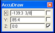
Accudraw is on when you see a dialog box where you can enter distances (XY&Z) of elements that you are drawing. Your curser will also have a box around it with a square crosshairs. This works with many tools (drawing lines, copying, scaling, etc.).
![]() (If Accudraw is not on,
click on the green and red crosshairs symbol in your toolbox Attribute
toolbox at the top of the screen.)
(If Accudraw is not on,
click on the green and red crosshairs symbol in your toolbox Attribute
toolbox at the top of the screen.)
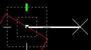
To ensure that you are drawing at right angles, allow your line to lock into the appropriate direction. (When your line become thick). Press enter to lock into this direction. When drawing at an angle, Accudraw will adjust to this anglular field. To return to the xyz orientation, press Shift and “T”.
11. SELECTION / PRE-SELECTION
You can pre-select before using other tools to alter more than one element at a time.
a. ![]() Using arrow (aka element selection) tool, click and drag to make a rectangle around the things you want to select.
Using arrow (aka element selection) tool, click and drag to make a rectangle around the things you want to select.
b. ![]() Use arrow tool to click on individual elements, holding ALT button to add to your selections.
Use arrow tool to click on individual elements, holding ALT button to add to your selections.
c. ![]() Use power selector (arrow with light bulb). Offers different methods
(areas), modes ( add/subtract from selected elements), or click on
arrow at bottom of box to select by colors, element type, levels, etc.
Use power selector (arrow with light bulb). Offers different methods
(areas), modes ( add/subtract from selected elements), or click on
arrow at bottom of box to select by colors, element type, levels, etc.