
Workshop 4 Notes, Week of September 19, 2005
1. ACS PLANE LOCK AND ACS SNAP LOCK
 Open the active locks menu, located in the bottom right corner next to the snap menu.
- The plane Lock forces the drawing plane to the ground plane.
- The snap Lock forces object snaps to attach at the ground plane.
There are a range of solid modeling options: shapes, extrusions, and smart solids.
2. SOLID PRIMITIVES
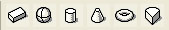
- To bring up the solid tools go to: Tools > 3D main > 3D primitives.
- These tools allow you to construct Slab, Sphere, Cylinder, Cone, Torus,
and Wedge by drawing a series of vectors to describe that solid.
- The Slab,
Cylinder, Cone, and Wedge all work in a similar fashion.
- When drawing a Sphere
however, the very center of the Sphere is placed along the ground plane.
To move the Sphere up, get into front view and use the
move tool to move the Sphere up to the ground plane by first selecting the
Sphere, then typing " F" to move Accudraw to the front orientation,
and then finally move the Sphere. To get Accudraw back onto the ground plane
type " T" for
top.
- For the Torus tool, it is good to type a value for the primary radius, secondary radius, and/or angle in the place torus dialog box.
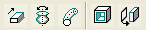
3. BOOLEAN OPERATIONS

- To bring up the 3D modify tools go to: Tools > 3D Main > TF 3D Modify.
- There
are a variety of tools in this palette. For now, we will just look at
the basic Boolean operations: Union, Intersection, and Difference.

- Construct
Union: Combines two objects into one solid object.
- Construct Intersection:
Creates a solid object as the shape common to two elements.
- Construct
Difference: Subtracts one object from another. First, select the object
to remain. Second, select the object to subtract.
4. 3-D CONSTRUCT TOOLS
- To bring up the 3D construct tools go to: Tools > 3D Main > 3D Construct.

- Extrude: Makes a planar object 3-dimensional. The original 2-D object must
be a closed object. A group of connected smart lines can become a shape using the Complex Shape tool in “TF Groups” toolbar. Creates the group of lines into a surface.
- Click on the closed object to drag to desired height.
5. SMART GEOMETRY (“True Parametrics”)
Tools > Feature Modeling > Feature Modeling
- Primitive Feature Solids: Slab Feature/ Cylinder placed within the Slab Sphere placed within Slab boundaries
- Difference Tool located at top right of Feature Modeling toolbar – Select Slab to keep, then object to create difference from, and left-click to accept.
- Modify parametric solid/feature located at bottom right of Feature Modeling toolbar – Select object; allows you to modify the dimensions of differences created by feature modeling shapes.
- Move feature located one above the modify button on the Feature Modeling toolbar – allows you to move/copy the feature model shape within the object.
- Features toolbar located 3 down on the left of the Feature Modeling toolbar – allows to create a hole within the slab by establishing a diameter then clicking on the object and moving the whole into place switching surfaces on the slab simply by sliding across it. (countersink holes can also be created)
NOTE: remember you can always look to lower left corner of the screen for any tool instructions
6. ARCHITECTURAL TOOLS
By default, these tools are typicallylocated on the left-hand side of the screen. If they are not, go to the menu item Architecture/Architectural Modeling (double-wide) or Architecture/Architectural Modeling (single-wide)
 The place Wall tool creates a 3d object with preset height and width
 - Select a starting pt. for the wall, followed by an end point (remember, if the acs plane and snap locks are on then the wall will start on the ground plane.)
- Intersecting walls can be connected in various ways: T- shape, L-shape with square ends, L-shape with mitered ends, and Intersection in which the first selected wall is spliced into 2.
7. MANIPULATING ACCUDRAW CONSTRUCTION PLANE
- With ACS plane and snap locks unchecked (off), a vertical wall parallel with the x-axis or y-axis can be drawn by switching the acs plane as follows:
- Select the Rectangle tool.
- Tentative Snap (simultaneously left and right click) the lower left corner of the face of the wall to be drawn on.
- Type ‘F’ (if wall is parallel to x-axis) or ‘S’ (if parallel to y-axis) – this will orient the acs plane currently located in the top view (‘T’) to either the Front or Side respectively.
- Type ‘O’ to offset from that corner within the plane you’ve now specified.
- Draw a rectangle on the surface of the wall.
 Using the ‘Construct Opening’ tool on the TF 3D Modify toolbar, you can select the rectangle, accept selection, select the wall, and accept selection to create a hole in the wall.
For a wall not drawn on either the x-axis or y-axis, it becomes a little more difficult:
- Make sure that the “Sticky Z Lock” is unchecked on the Accudraw window. This allows more 3-dimensional maneuverability.
- Select the Rectangle Tool and Tentative Snap the lower left corner of the face of the wall to be drawn on (as before).
- A Quick Key Combo needs to be enter to allow us to establish the plane: Type ‘R’ followed by ‘A’.
- Establish the origin of the new coordinates (by select the point you tentatively selected).
- Establish the x-axis by selecting the lower right point on the same face.
- Establish the y-axis by selecting the upper left point on the same surface.
- Now, you may type ‘O’ to offset the starting pt of the rectangle within the newly establish plane as before and draw a rectangle (a hole is created using the same method as above.)
NOTE: when in the middle of tool commands, left click = accept, right click = reset