
Workshop 8 notes, Week of October 16, 2006
Materials and Lighting
1. FILE TYPES FOR TEXTURE MAPPING
These files are interchangeable between drawings and are stored outside the .dgn file:
Material Palette File (file extension “.pal”) – definition of materials. Can be one of three types
- Definition by properties [e.g. color]
- By procedure [by specific algorithm]
- By texture mapping [literally draping image onto a surface]
Materials Table (file extension “.mat”)
- References the palette files according to object or a combination of layer and color.
2. SURFACE MODIFICATIONS
Tools>surface modeling>modify surfaces
Project Trim
- Make rectangle in plan and make circle inside rectangle.
- Turn off ACS snaps and sticky z lock.
- Move circle above the rectangle (using the ‘F’ or ‘S’ construction plane).
 Use the “project trim” tool on the modify surfaces palette (2 nd icon).
- Make sure ‘orthogonal’ and ‘keep profile’ are selected in the trim dialog box.
- Click on the rectangle, the circle, and left-click to accept.
Stitch Surfaces
- Draw a second rectangle adjacent to the first rectangle of equal width.
 Use “stitch surfaces” (4 th icon) to join the two surfaces together.
- Click on first object, second object, and left-click to accept.
Construct Trim
- Overlap a new rectangle over the second (in effect cutting partway into first).
 Use “construct trim” tool (1 st icon).
- With “Trim first surface” option selected, pick first and then second surface to trim.
- Left-click to accept.
Split Surface
- Pick surface with circular projected hole in it.
 Select “split surface” tool (8 th icon).
- Choose object then corner vertice.
- Move, and surface trims accordingly.
Extend Surface
 Select “Extend Surface” icon (9 th icon) and make sure “extend mode” is “tangential”.
- Select edge of rectangular surface and move to extend surface size.
Convert Surfaces to Solid
- Place rectangle and build 3D elevations to create an “open container”.
- It is possible to make the sides by clicking on a vertice, moving to the ‘F’ or ‘S’ construction plane, tentative snapping the next vertice and pulling up.
- Copy this rectangle to the opposite side, and create the other 2 sides.
- Use the "stitch surfaces" tool to join the rectangles together (click all 5 surfaces and left-click to accept).
 Use "Convert 3D" tool (3 rd icon), “convert to solid” option, to convert to solid object (click ‘container’ and left-click to accept).
3. BASIC LIGHTING SETUP
Tools>3D Main>3D Primitives
- Draw base rectangle (with ACS snaps on).
- Turn off ACS snaps and use the slab tool to place a slab on the rectangle surface (tentative snap a vertice, hit ‘o’ for ‘offset’ and start drawing in the rectangle).
- Using the same method, place a cylinder and truncated cone on the rectangle (it may be necessary to check different views to make sure your primitives are in the right place.
 Using the “Change Element Attributes ” tool (In the main tool palette, 8 th one down on the left side), check off ‘color’ and make each of the three primitives a separate color.
 - From the vertices of the base rectangle, create 3 “light poles” (fill, key, backlight).
- In View Attributes (from “B” menu), check to make sure ‘constructions’ is checked on, and then make sure plane locks and sticky z are off.
 Under Tools>visualization>Rendering, choose the “Define Light” tool.
- Make sure the mode is “create” and place spot lights on two of the ‘poles’ (intensity of 0.5 and 1, key and back).
- Create point light (intensity 0.5) on the last pole.
- Check global lighting and turn off solar light.
- Under View attributes, turn off constructions.
4. STANDARD RENDERING
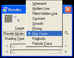
It is possible to render through a range of algorithms. Use the render tool to test:
- Wiremesh
- Hidden Line
- Filled Hidden Line
- Constant
- Smooth
- Phong (turn off or save shadow maps under Settings>Rendering>General lighting)
- Ray Trace
- Ray Trace – shading type: anti alias
5. SIMPLE MATERIAL ASSIGNMENTS
Settings>Rendering>Materials
- Go to Table>Save As to start a new table.
- Go to Palette>Open and choose C:\ProgramFiles\Bentley\Workspace\Triforma\atf_us_ncs\materials.
- Open “finishes.pal” and assign “flat warm grey” to the slab.
- Right-click on the finish.
- Go to “Assign,” then choose the object. The material should then have a “+” next to it and contain the layer and color of the object selected.
- Open palette “glazing.pal” and assign glass to sphere.
- Open palette “metals.pal” and assign brass to cone.
- Open palette “floors.pal” and assign tile semi gloss to rectangle.
- To preserve the new settings, right-click on the table name and save and then on the palettes to save.
6. BACKGROUND MAP AND DISTANCE CUE
Settings>Design File>Views
- Browse for a Background image and check off the box (C:\ProgramFiles\Bentley\Workspace\Triforma\atf_us_ncs\materials\pattern\SkyBlueSmClouds.jpg) Settings>Rendering>View Attributes (or Settings>Rendering>Setup>Render Attributes).
- Change “ Distance cue” to “fog”.
- In the setup menu, it is possible to change near distance, density, or far density
- In Settings>Rendering>General or in the Setup, can change “Fog color” (pick light blue).
- Lower far density to 0.25.
- To turn background off, go to Settings>Rendering>View attributes or to the “B” menu>View Attributes and check the background off.
7. PROCEDURE TEXT FILE
Settings>Rendering>Materials
- Palette>open and go to C:\ProgramFiles\Bentley\workspace\Triforma\atf_us_ncs\materials.
- Open “ proctext.pal”.
- Assign “dutch bond” to brick slab, then render.
8. CREATE MATERIAL
Settings/Renderings/Materials
- Go to Palette> New and save “grue.pal” (can right-click to save or rename).
- Start new material “grue1” by right-clicking on the palette and clicking “new material”.
- Pick base color by clicking on the white square next to color.
- Adjust sliders for: Ambient Diffuse Specular Finish Transmit Reflect Refract.
- Add bump map by clicking on the “pattern” button and switching the “Map” to “bump” (Use StuccoBump.jpg from C:\ProgramFiles\Bentley\Workspace\Triforma\atf_us_ncs\materials\bump).
- Reduce height to 0.50.
- Resave palette.
- Open up assign materials dialog box (Material>Assign).
- Open palette “grue”.
- Assign grue1 to cone.
- Render.
- Reserve for next time.
9. MODIFY PROCEDURE TEXTURE MAP & CREATE YOUR OWN
Palette> Open
C:\ProgramFiles\Bentley\Workspace\Triforma\atf_us_ncs\materials\proctext.pal.
- Double click on “brick”.
- Double-click on procedure map for brick in assign materials dialog.
- Save palette as myproc.pal in your x: drive.
- Copy brick (dutch bond) to mybrick (dutch bond).
- Hit edit button, change mortar color.
- Save palette (note all names unique (palette and material)
10. TRANSPARENT OBJECTS
- COPY materials1a directly and files from classes folder.
- Relink individual person files
11. TO MAP IMAGE
- In the new palette, right-click for “new material”.
- Hit the “Pattern” box.
- Click on the magnifying glass to browse for image.
- Turn off transparent background.
- Under “units” make sure it is assigned to “surface” to stretch the image to the surface area (“Master” tiles it in 1’x1’ modules).
- In the model, build a new rectangle in a new color.
- Assign image to rectangle.
- Render to view.
12. ENVIRONMENTAL MAP
Table>environment maps
- Set environment maps (sky2.jpg).
- Select “raytrace.pal” and assign mirror to rectangle.
13. SAVING RENDERINGS
- V iew size in Settings>Rendering>View size.
- Set to 640x480 (make sure “proportional resize” is off).
- Save image file by going to Utilities>Image>Save (check options and save by browsing to folder).
- To see image in microstation, go to Utilities>Image>Display .
SEE ALSO :
http://www.arch.virginia.edu/arch541/Handouts/render/attrib.html {material attributes http://archweb.arch.virginia.edu/~ejm9k/Handouts/render/rtraceset.html {raytrace attributes http://archweb.arch.virginia.edu/arch541/Handouts/render/setup.html {gen render attributes http://www.arch.virginia.edu/arch541/Handouts/render/viewatr.html {view attributes http://archweb.arch.virginia.edu//arch541/Handouts/sample.htm { sample marble