October 4, 2018 Workshop 7 Notes
LIGHTING
AND MATERIALS, RENDER FARMING
This workshop is developed after techniques described in the Robinson text,. it contains examples that are reinforced by background concepts in Chapters Chapter 14 + Chapter 15 (part), pages 349 402
1.
Shaders in Maya are based upon standard rendering algorithms and
include the following types:
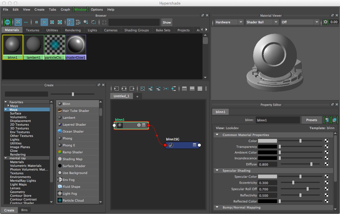
These types of shaders are acessible through the hypershade dialog box or Window/Rendering Editors/Hypershade
2. Lighting types & 3 point lighting - Chapter 14
Lighting types commonly used are 1) Ambient, 2) Distant/Directional, 3) Point and 4) Spot Light which appear from left to right in the Rendering Shelf tab in Maya. Ambient light provides general background illumination. A Distant/Directional light provides parallel light rays from a specific angular orientation, and may be used to mimic such distant lights as sunlight or moonlight. A point light is an omni-directional light that sends light out in all directions from a single location. A directional light sends light in a specific direction at a specific angle from a source location to a target location.

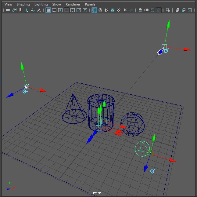
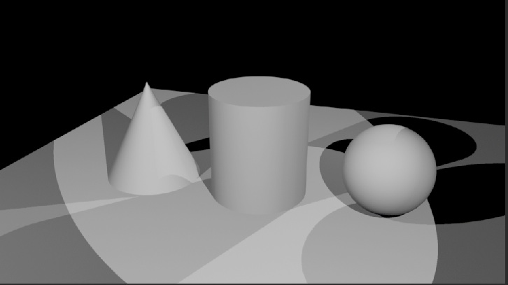
Key and Fill Lighting: A typical three point lighting setup has a Spot light (also known as a Key light) to the upper right of model at full intensity to provide high contrast shadows, a Point light (also known as a fill light) to the upper left of the model at lower intensity filling in middle gray values, and a back spot light (also known as a back key light) at lower intensity than the front spot light and that provides some three-dimensional depth to the rendering.
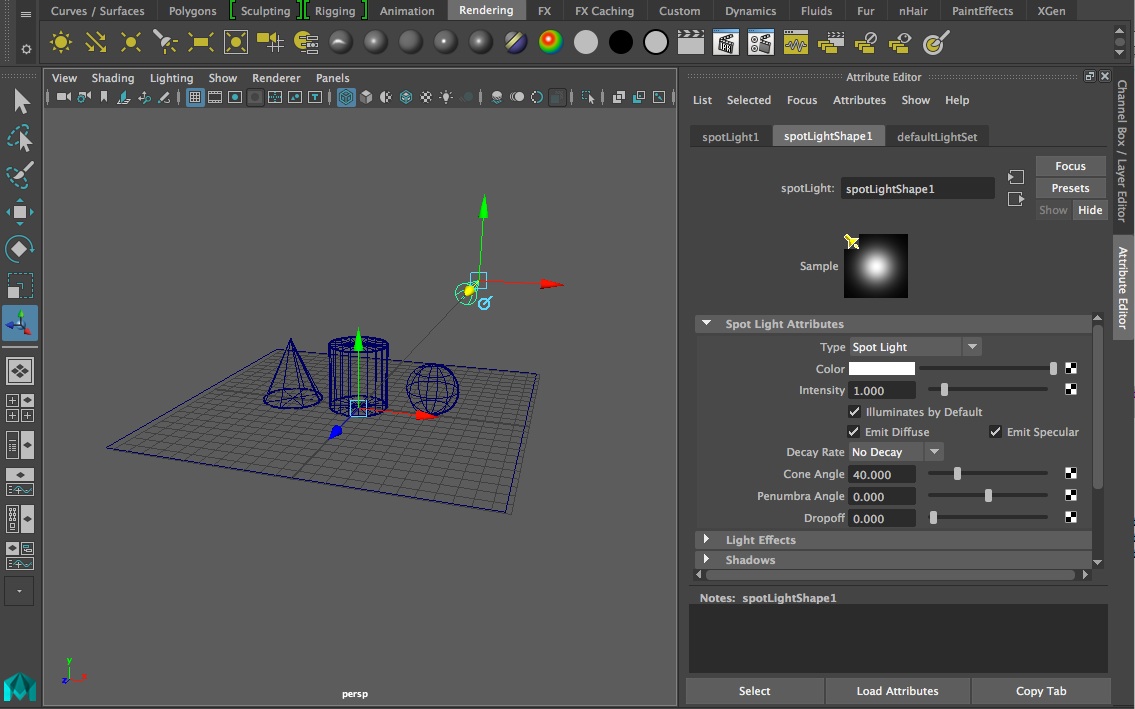
Key light set at full intenstity and positioned using the show manipulator tool (selected tool on left-hand side of Application window).
 |
 |
3. Materials Some Definition of Textures and Methods
Materials
reference attribute nodes that
determine look of an object. This includes
Texture
– an
material that is mapped to object
Types: procedural (based on
an algorithm) and
image (based on a
photograph).
Bump Map – image read for its gray scale value that makes a material have the appearance of a surface relief
4. Menu items in Hypershade window (Left to Right)
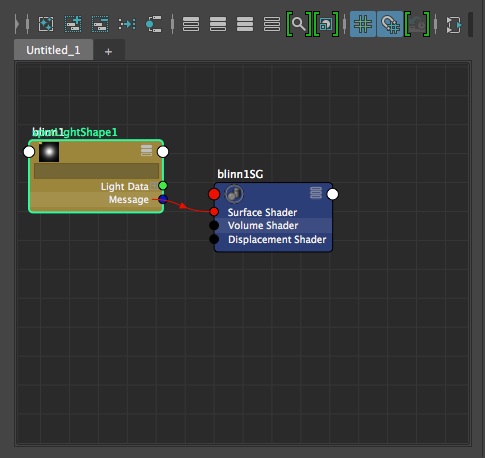
From left to right the icons above the work area window (see above) have the following functions . Ignore for now those functions which are grayed out:
Clear Graph bar – clears out any nodes in work area
Add selected nodes to graph
Remove selected nodes from graph
Rearrange graph
Clear graph materials on selected objects
Hide attributes on selected nodes
Show connected attributes on selected nodes
Show primary attributes on selected nodes
Show attributes from custom attribute view
Toggle the display of attribute filter field
Toggle the icon swatch size
Turn on grid in graph window
Turn on gravity grid in graph windows
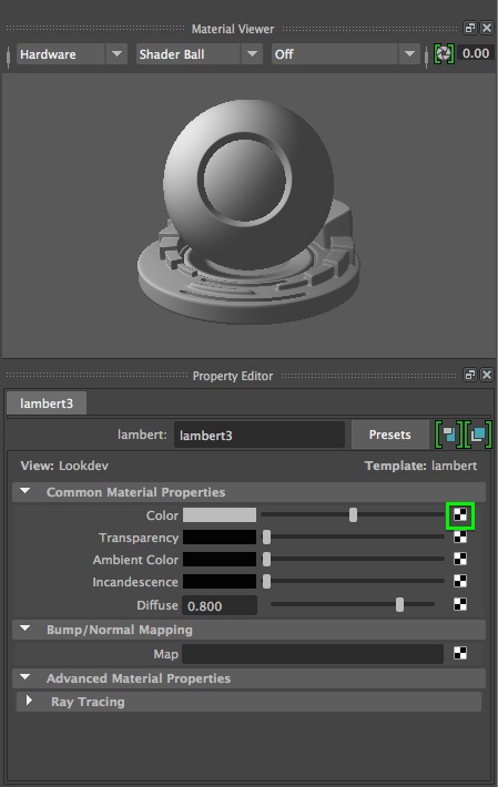
5. Basic material properties:
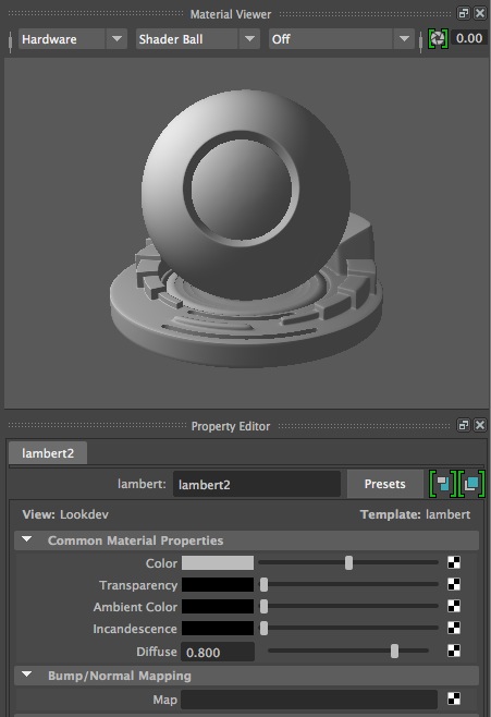
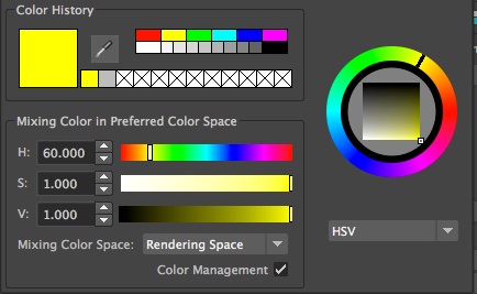
Color
– RGB or HSV selection
model color
Transparency – degree to which material is transparent
Ambient Color – brightness or darkness of whole material
Incandescence – create appearance of giving light
Bump mapping – makes a surface appear bumpy
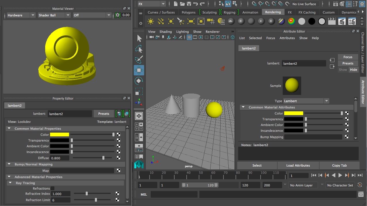
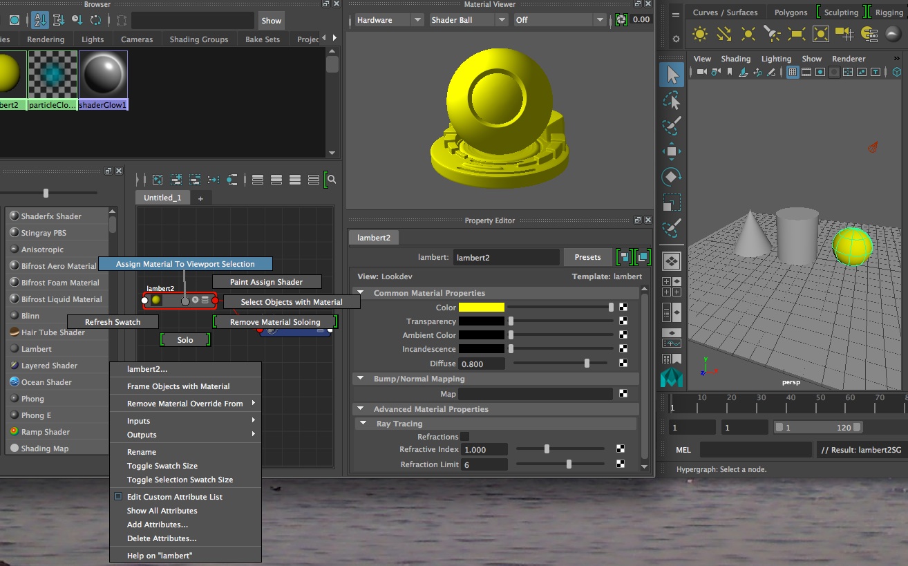
6. Example of use of simple material definition and assignment
Change color of an object
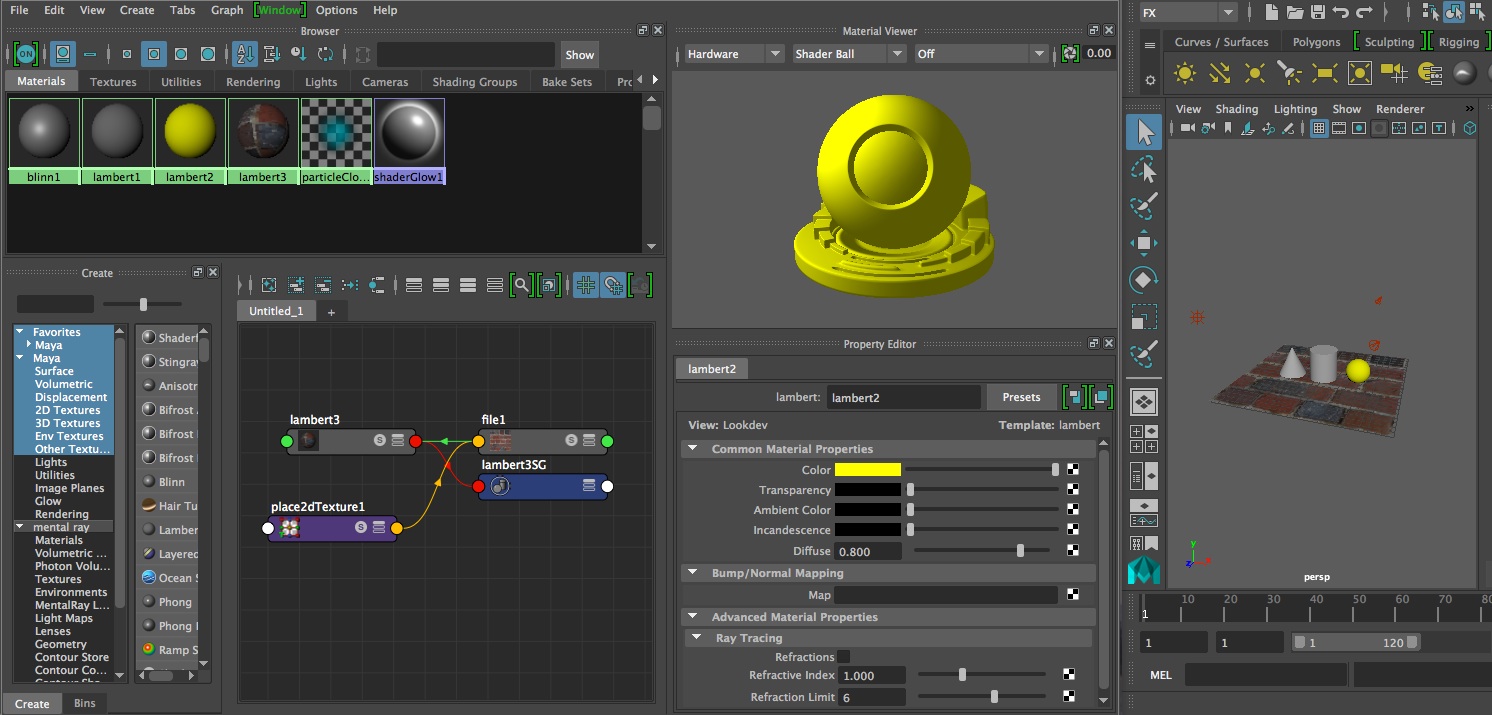
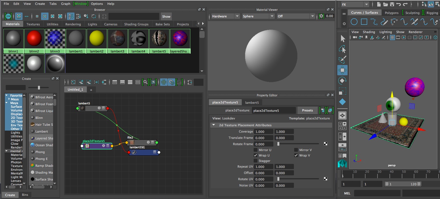
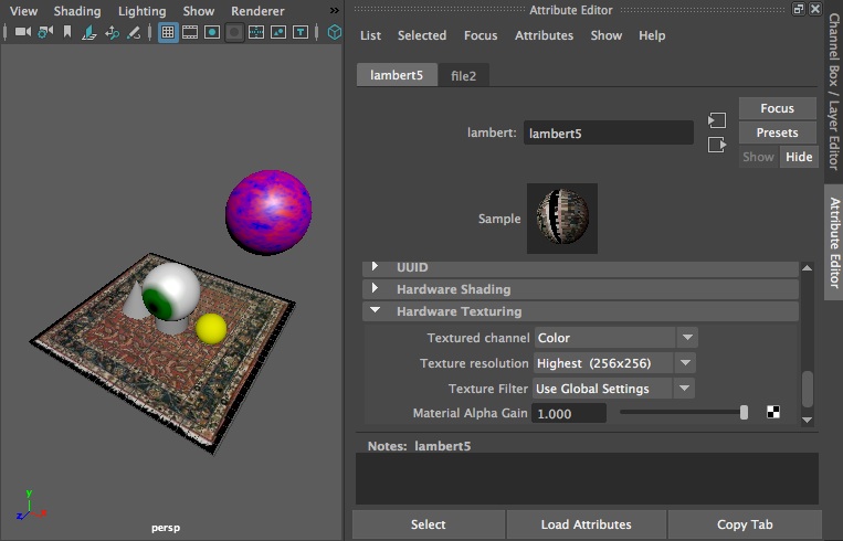
6. Texture mapping nurbs surface
Prepare brick.jpg file or somephoto.jpg file. Make a material from a lamber shader. In the color selection area on the right-hand side of the the screen, select the checkered symbol and follow the dialog box to load the brick.jpg file.
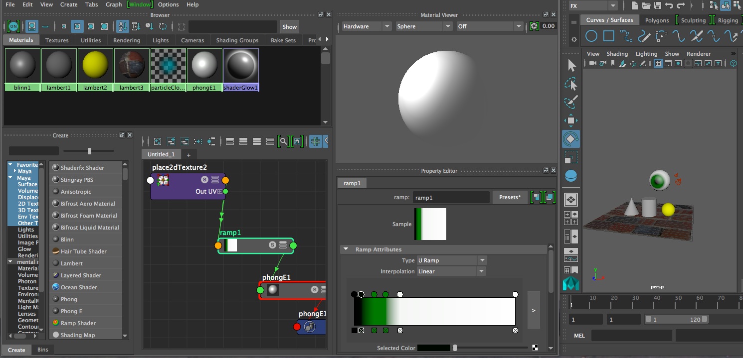
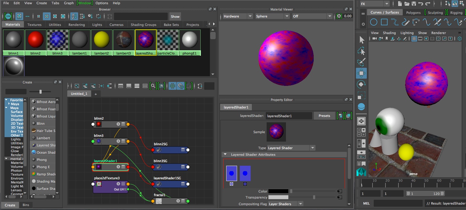
7. Ramp texture (eyeball)
8. Layered Shader
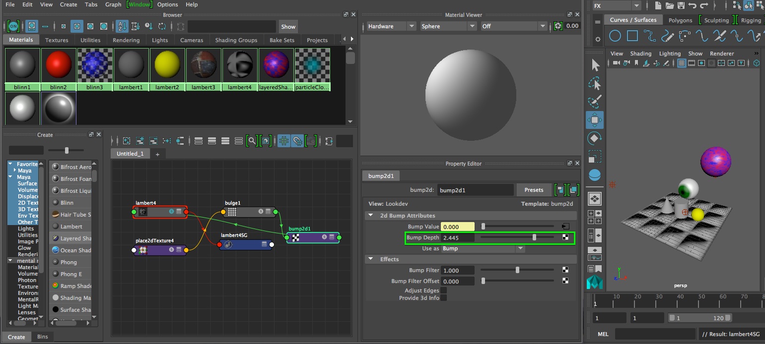
9. Bump Map
10.
Projection Map
[If surface appears to be moving through texture, then in Rendering mode, select the surface, and then from the Texturing menu select “Create Texture Reference Object”]
11. To Improve Quality of Rendering
11. 3D Paint Tool
RENDER FARMING
Rendering farming, distributed rendering to remote computers, is possible in Maya for Mental Ray and Maya Software rendering options. Basic setup instructions (requires login) are typically posted on the School of Architecture web site web. Note that these instructions are continually being updated. The rendering is completed in batch processing mode such that once a job is submitted it is not necessary to stay logged in while it is being processed. The following steps illustrate a typical render farming sequence.
1. Create a folder on the School's "ScanTemp" server typically with your name (e.g., wdisney).Typically "ScanTemp" is visible on any public computer with thie School of Architecture.
1a. On a private Mac on grounds or through VPN use the menu item "Go/Connect To Server":
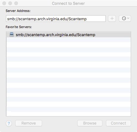
1.b Similarly, on Windows use the "Run" command and enter
\\scantemp.arch.virginia.edu\ScanTemp
2. Within Maya, setup a project directly on "ScanTemp" under your folder (e.g,"wdisney/batchRenderingTest")
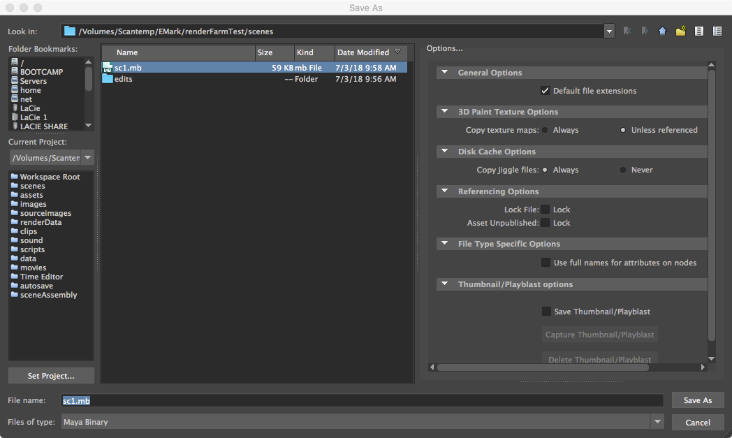
3. Create or open a pre-existing scene file and save it to the "scenes" subfolder of the project folder on "ScanTemp" similar to previous workshops.
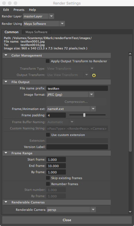
4. Setup for batch rendering with either "Maya Software" or "V-Ray" in the "Render Settings" tool similar to previous workshops.
5. Go to the "Rendering Module" in Maya and then go to the menu sequence "Render/Create Backburner Job ... ".
6. Within the next stage, you maybe asked to save the scene one time. Save it to your project's scenes folder on scan temp.
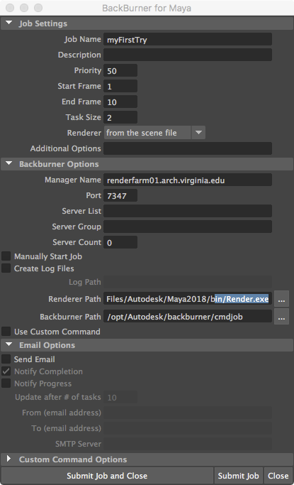
7. The following backburner settings are typical.
Note that a number of changes from the default setup are necessary:
7a. Create a "Job Name", such as "myFirstTry".
7b. Set the "Manager Name" to "renderfarm01.arch.virginia.edu" (the address of the render server).
7c. Set the 'Port" to "7347."
7d. NOTE: The "Renderer Path", set by default, will be different on Windows and on the Mac and needs to be as follows on both platforms. There is a blank space " "between "Program" and "Files" in this path address:
C:/Program Files/Autodesk/Maya2018/bin/Render.exe
7e. The backburner path should be set to:
/opt/Autodesk/backburner/cmdjob
Note: the backburner pathway may need to be set to /usr/discreet/backburner/cmdjob on some computers (this is currently being investigated)
8. Choose the "Submit Job" button, and look for the rendered frames in the images folder under your project Folder on ScanTemp. At this point it is no longer necessary to remain logged in for the backburner batch process to proceed.
9. Whe the images are rendered, copy them from ScanTemp to the local desktop and compile them within Quictime Pro as per the method of earlier workshops. Do not attempt to compile the images over the network due to a number of potential errors.
10. The full setup PDF file (requires access through UVA login / netbadge) also illustrates how to send email to your self notifying when the backburner task is completed. In addition it describes how to monitor the status of the rendering process on a School of Architecture Windows computer.
11. You can monitor render jobs on the web from on grounds on Cavalier (not Wahoo), or via VPN access:
http://renderfarm01.arch.virginia.edu/backburner
The web page also requires a login:
sarc
render
note: there is one bug in the web monitor that is acknowledged by Autodesk - it only shows the first letter of the job name, owner, and server name.
12. Tutorials on VRay and Maya are published on the Chaos Group Web site. This primer is the most relevant to our needs.