September, 29, 2020 Workshop 8 Notes
Introduction To Rendering With V-Ray
V-Ray is an implementation of a Global Ilumination light energy modeling method that is based upon realistic simulation of lights and materials and takes advantage a probabilistic sampling to reduce the level of computation time. The implementation within Maya allows for the continued use of some regular Maya shaders and also provides an additional set of V-Ray shaders with more advanced simulaation properties.
Tutorials on VRay and Maya are published on the Chaos Group web site. The primer is the most complete reference for our needs. The V-Ray tutorials are a good place to begin toexplore different materials and simulation methods.The notes here reflect a shorter and quick set of examples that help to establish a quick introduction, but the Choas Group web site is best for more thorough explanations and details.
As noted on the Chaos Group overview web site, the following Maya (non V-Ray) shaders are supported:
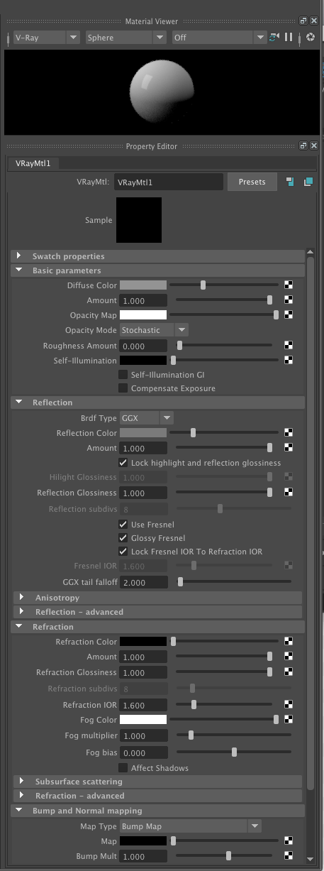
For these materials, the supported parameters are:
In addtion, the following Maya lighting types are also supported:
See the Chaos Group web site for an overview of V-Ray material shaders and V-Ray lights.
In part I below, a few variations on basic VRay material and their properties are adjusted. The full set of options and range of values for this type material is expanded in detail on on Chaos Group web site.
Part I: Vray Material Shader Example with IES Light
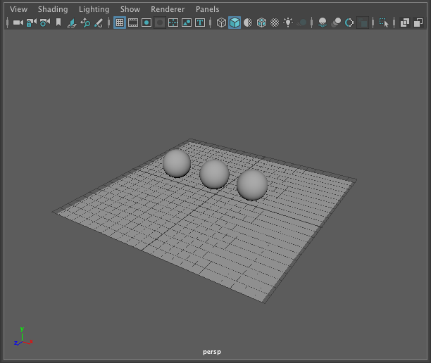
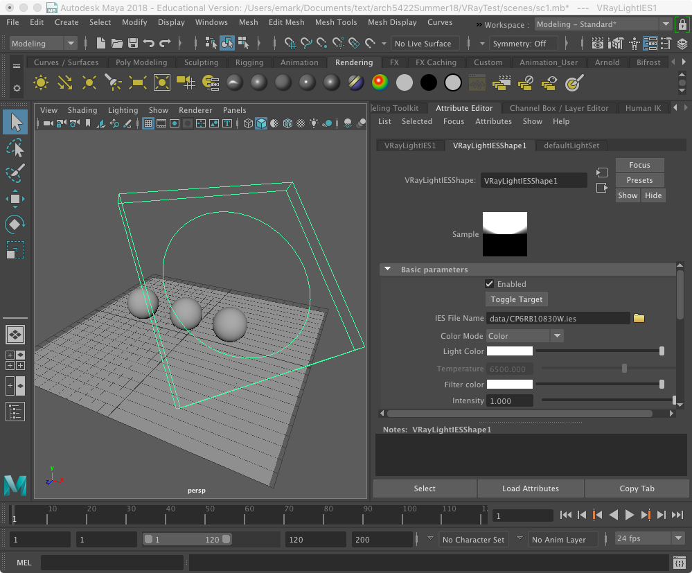
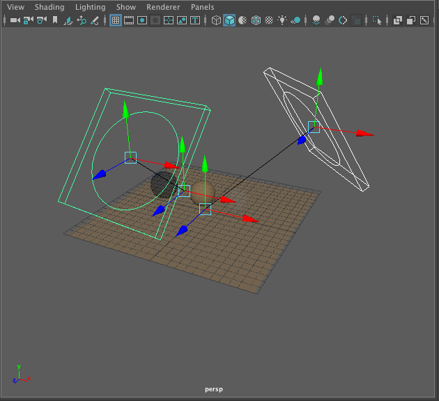
1. Create a project folder "VRayTest" and save a scene "sc1.mb". Next, create three polygon spheres above a polygon plane as shown below:
2. Go to the V-Ray tab, right-mouse click on the "V-Ray IES Light" symbol, second one from the the right-hand side of the light types, and add the light to the model space.
![]()
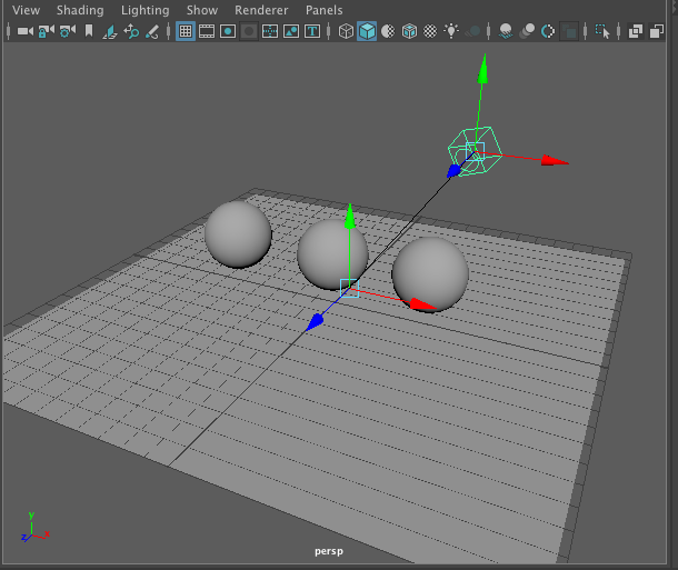
3. Use the menu item "Modify/Show Manipulator" too to position the light above and looking down at the center sphere similar to how the technique was use used in previous tutorials with respect the spotlight for Maya Software.
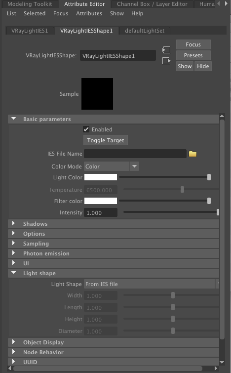
3. Open the properties window for the light and the tab "VRayLightIESShape1" as illustrated below. Next, open the sub-areas named "Basic parameters" and "Light shape" as also illustrated below. IES refers to Illuminating Engineering Society data that is typically provided by lighting manufacturers. Here we will use an IES data file CP6RB10830W.ies which holds data for the simulated light intensity and geometry profile for a Core Pro lighting fixture made by Phillips Lightng (see the original web source of the data file for addtional details).
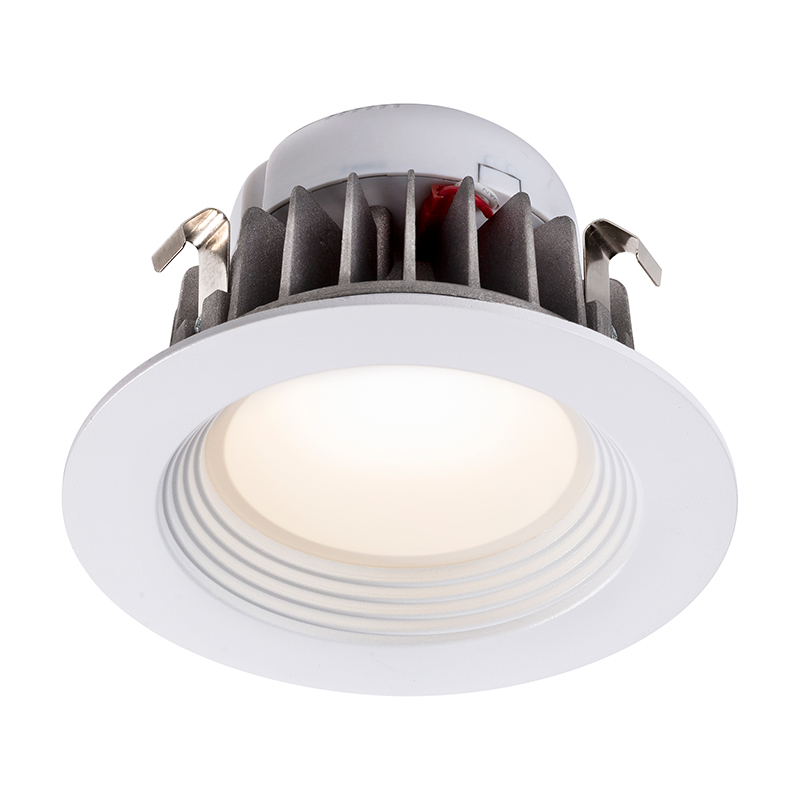
Core Pro LED Light by made by Phillips Lighting.
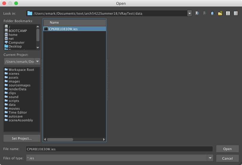
Download the file CP6RB10830W.ies and place it inside the "data" subfolder of the project folder.
Within the "Basic parameters" subarea, and adjacent to the "IES File Name" blank text field, select the yellow folder and then select the IES file CP6RB10830W.ies from the project "data" subfolder.
Once the IES file has been loaded, the view window in Maya will be changed to match the Core Pro lighting fixture.
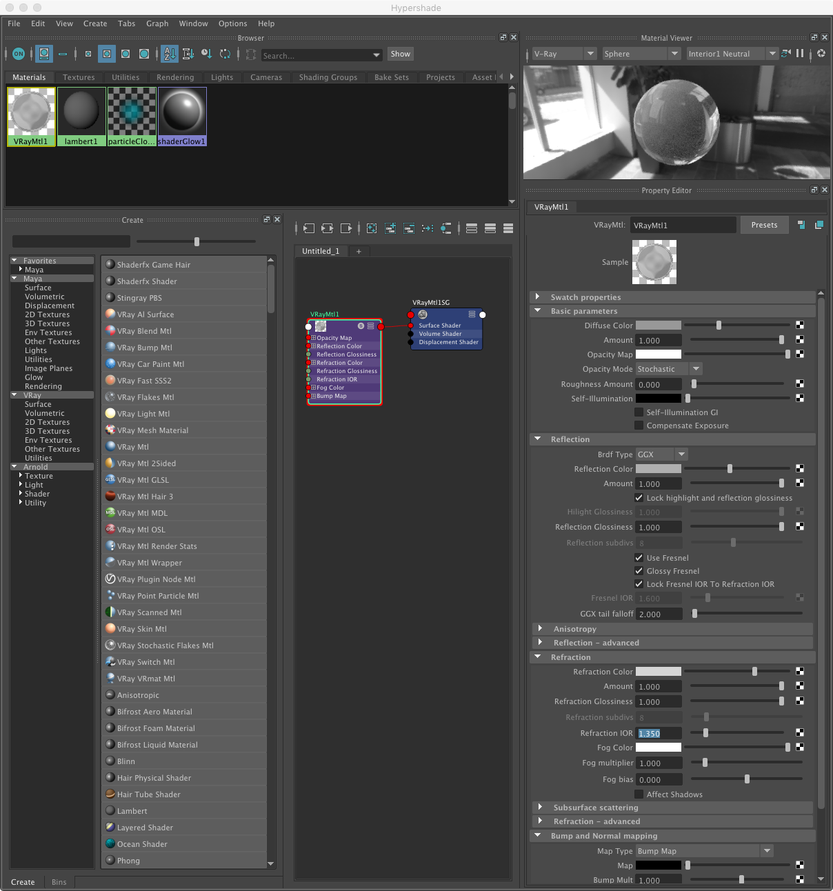
4. Now, under the menu item "Windows/Rendering Editors/Hypershade" open the hypershade panel and review the
"Surface"
shaders available for V-Ray.
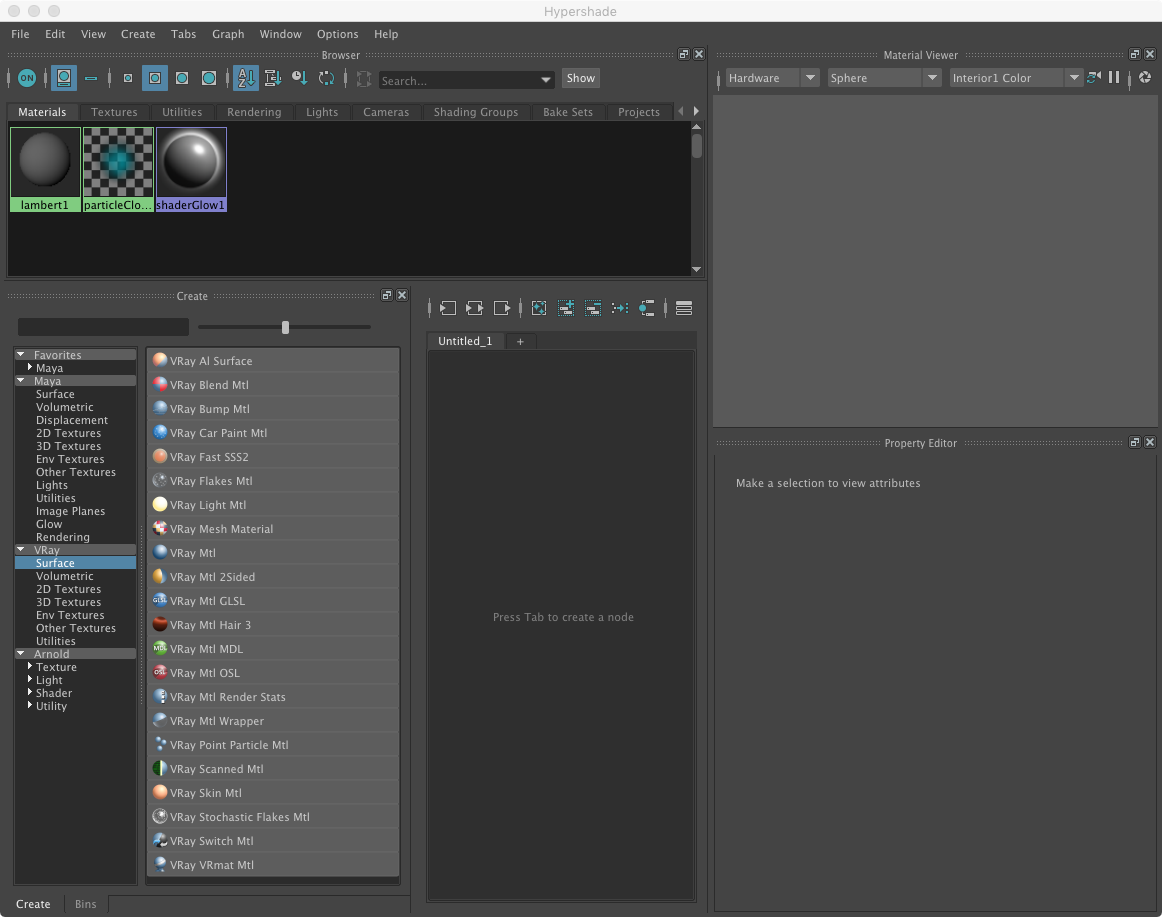
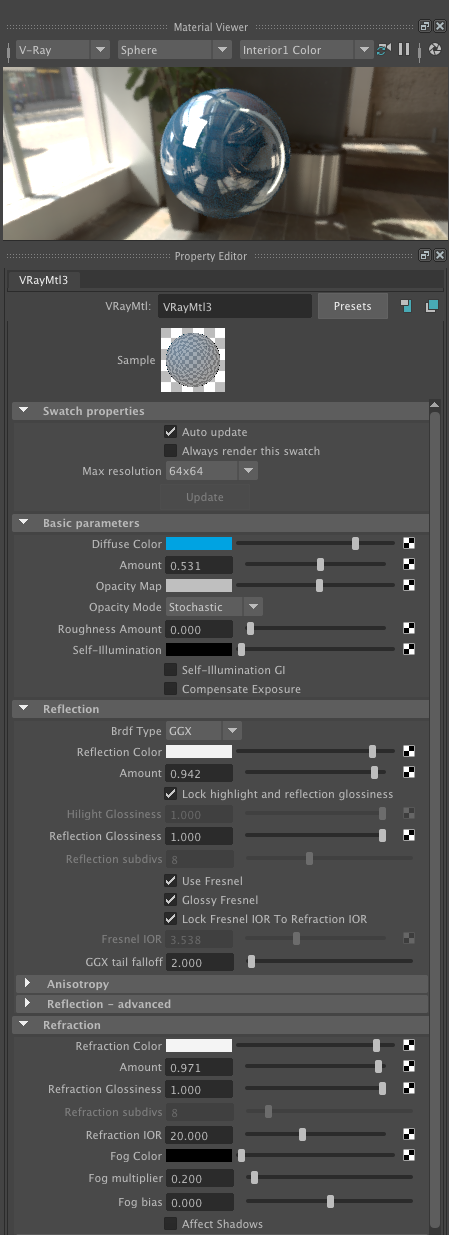
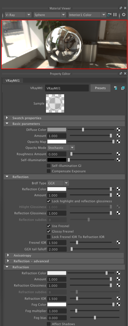
4. Select the generic type V-Ray shader named "VRay Mtl".
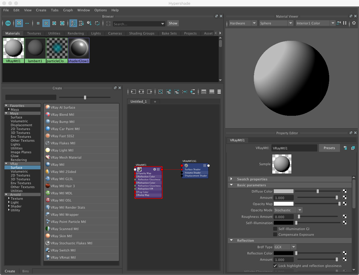
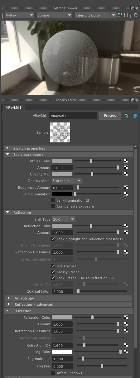
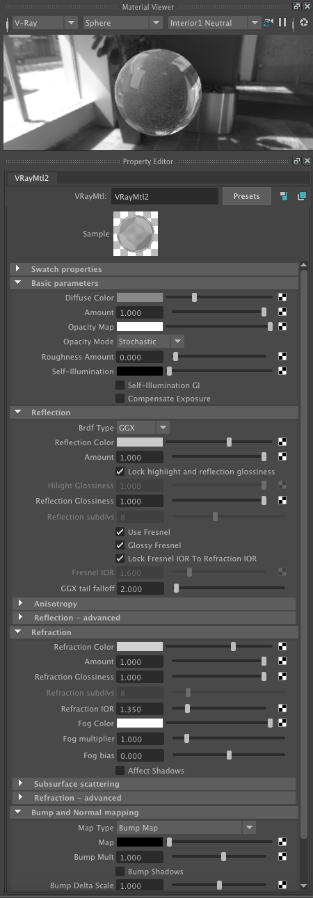
5. Within the property editor change the Material Viewer from "Hardware" to "V-Ray", and change the sliders for the "Diffuse Color", "Opacity Map", "Reflection Color" and "Refraction Color" to light gray (about 1/3rd of the way from left to right). These values 1/3rd the way from black to white in effect make the material less bright, less reflective , and less apparently refractive. Next, assign the shader to the rightmost sphere in the model. Note: The "Opacity Map" is actually a somwhat inappropriate way to control general transparency, but here is used as a quick method to create the appearance some transpanency. (It's actually better used in a different context, which is to map an image where darker colors indicate transparency, but that is beyond the sope of this current introduction). See step 16 for a more appropriate and revised approach where this material's properties are reset. In particular, note in step 16 that the IOR (index of refraction) for glass at IOR = 1.5. is used.
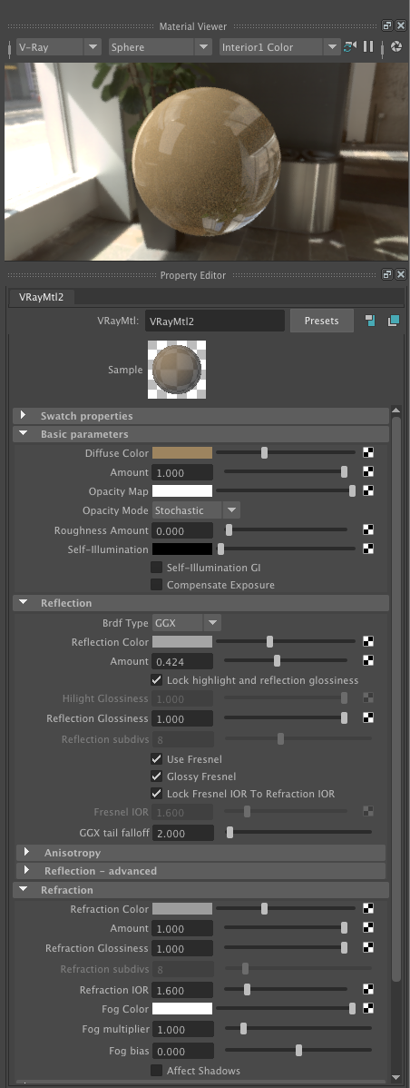
6. Create a second VRay "VRay "mtl" shader with the same properties, except let the "Diffuse" color have the appearance of "brass" or "shiny copper", and put the "Opacity" slider all the way to the right so that the adjacent color is white. Next, assign the shader to the center sphere in the model and to the planar polygon.
7. Create a third VRay "VRay "mtl" shader with the same properties as the first one, except turn on sub-surface scattering. Next, assign the shader to the remaining sphere in the model.
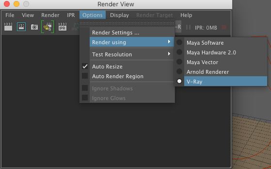
8. Next, open the "Render View" window, and go to the menu item"Opens/Render using/V-Ray".
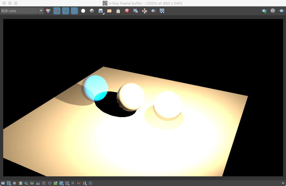
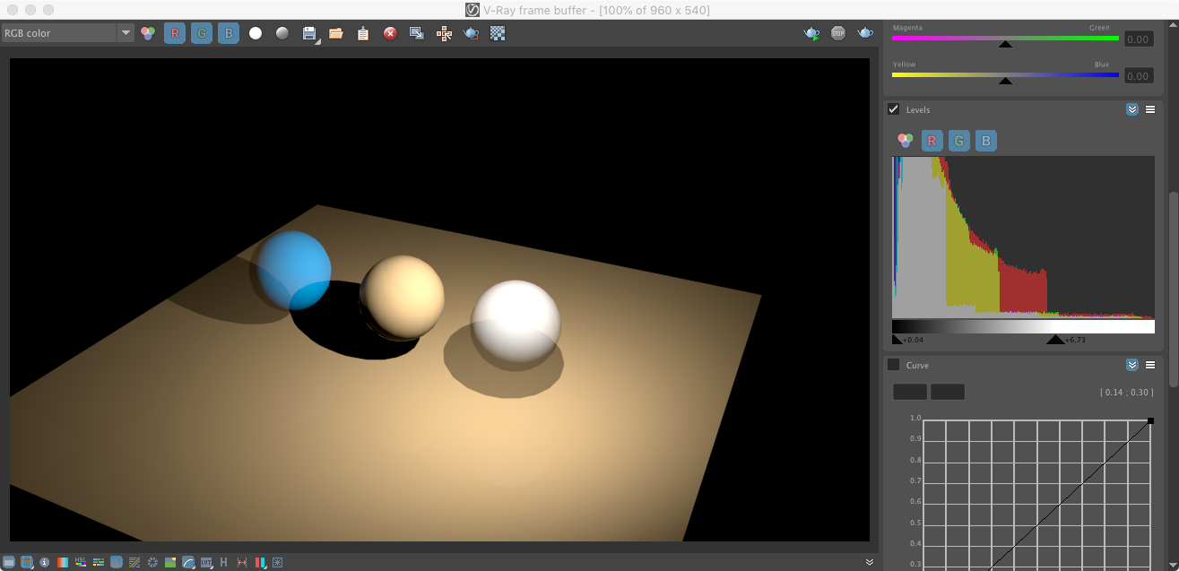
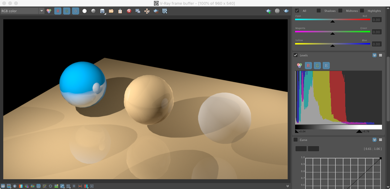
9. Select the "Render" icon in the upper left hand corner of the "Render View " window, and note thatt the "Render View " window is replaced by the V-Ray Render Buffer. In the first pass, the rending is likely to be inappropriately exposed.
10.However, select the first and the sixth icons on the lower left hand corner of frame buffer view window in order to activate the "corrections control" tools on its right hand side.
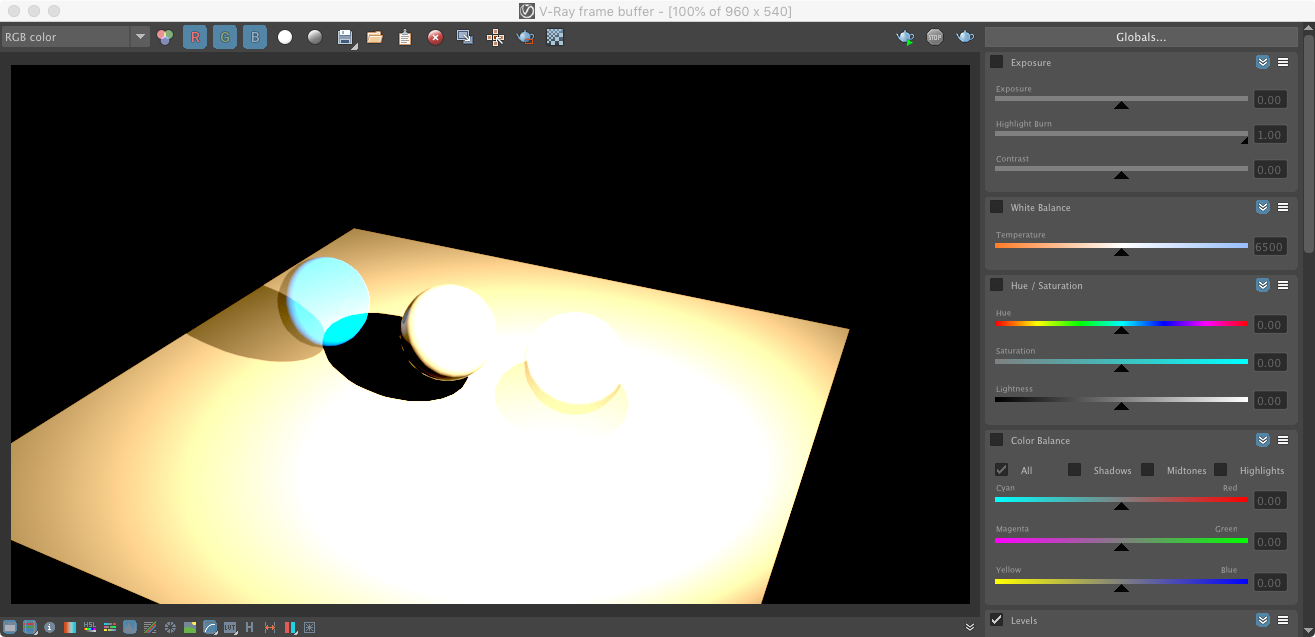
11. Next, scroll down the options on the right-hand side of the frame buffer view window until finding the "Levels" graph. Note that the check-box is "on" due to the selecting the "sixth" icon in previous step 10.
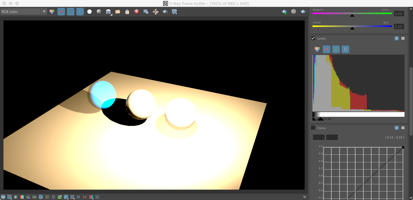
12. Next, just below the graph select the rightmost upward triangleand shift it towards the right end of the graph. Simlarly, select the leftmost upward triangleand shift it slightly towards the left end of the graph. Continue to adjust the two triangle until the rendering appears properly exposed. Note that the left-most and right-most sphere appear different due to the sub-surface scattering property being added to the left sphere. However, our rendering itself was completed without adding on the sub-surface scattering option turned on.
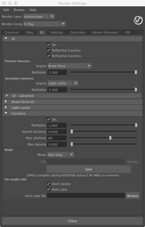
13. Next, go to the render settings for V-Ray. the "GI" tab in the first area labelled "GI" turn the upper check-box to "On" as well as the check-boxes for "Reflective "Cuastics" and for "Refractive Caustics". In the fifts area labelled "Caustics" turn the upper check-box to "On".
14. See the scattering of light impacts below the sphere in the rendering that follows.

15. Add a second IES light of the same type.
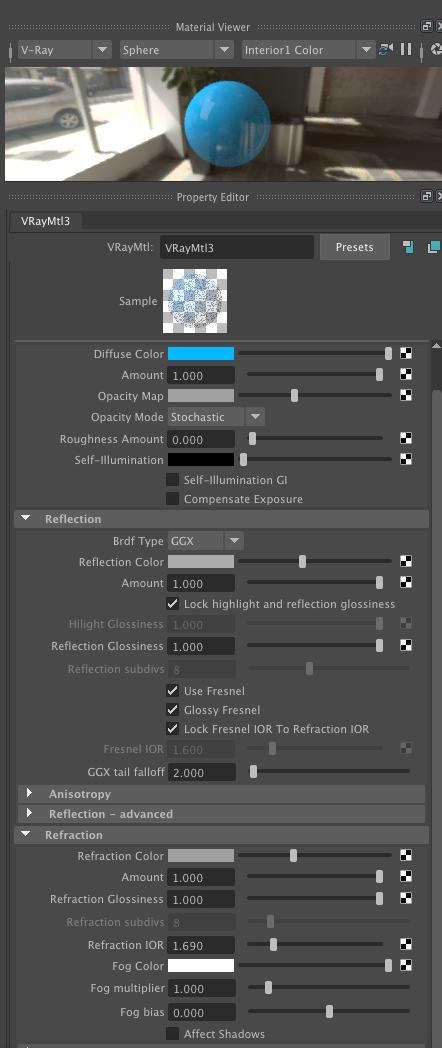
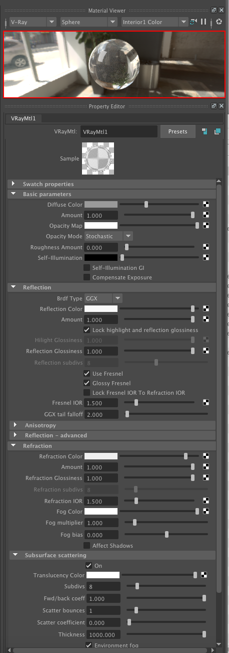
16. Increase the index of refraction (IOR) to 20 (unusully high, such as very a highly polished metal) and adjust the "reflection" and the "refraction" color sliders to the right be closer to white for the last material,. Also, adjust the "Opacity Map" color to middle gray scale. A source of IOR values is availble at https://pixelandpoly.com/ior.html well as other web sites.
17. Re-render.
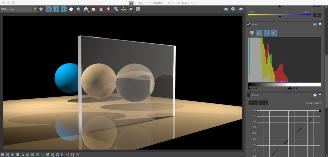
18. The sphere to the right still is somewhat unrealistic in that it appears to be more the non-reflective transparency of paper like but less like perhaps the transparency of glass. As solid glass it would bend light in a way that may also not allow full transparency, but it would bend light more and also be more reflective. To clarify this situation we return back to the properties of the material assigned to this object. In this revision to the properties for the matieral, an IOR of1.5 to is assigne to refraction. We also use an IOR of 1.5 for the material's fresnal effect (determines reflectivity at different viewing angles). In addtion the opacity map slider is set to full white (no opacity), and the reflection slider is also set to full white (maximum reflectivty). Note that rather lower the intensity of the "Opacity Map", the level of transparency is determined by the IOR value of 1.5 that is assigned to refraction. Here in the "Material Viewer" as in the model itsef the sphere is not self-evidently transparent when the revised material is applied to a solid sphere. However, when the same material is applied to flat box, the transparency of the material is evident.
In the following rendering, a flat vertical wall-like box is added. The box and wall are assigned the revised first material.
19. In one more step, subsurface scattering is added to the first material.
Note that GI and Caustics must be turned on (from step 13 above):
Re-rerendering produces the following result:
Part II. Simulation of Water
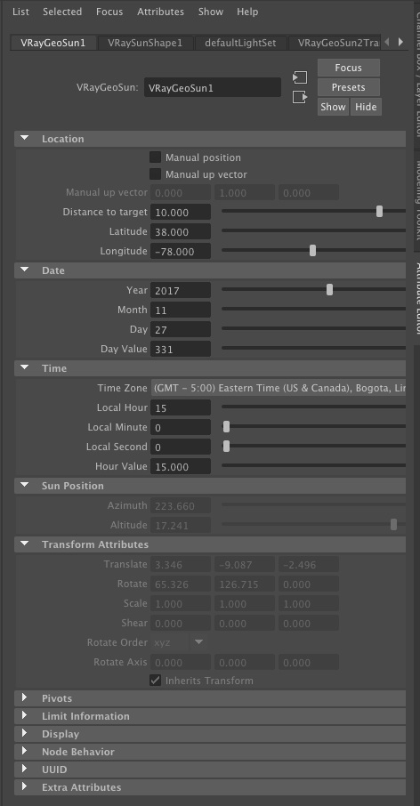
1. Go to the V-Ray tab, right-mouse click on the "Sun" symbol on the right-hand side of the light types, and add a sunlight to the model space.
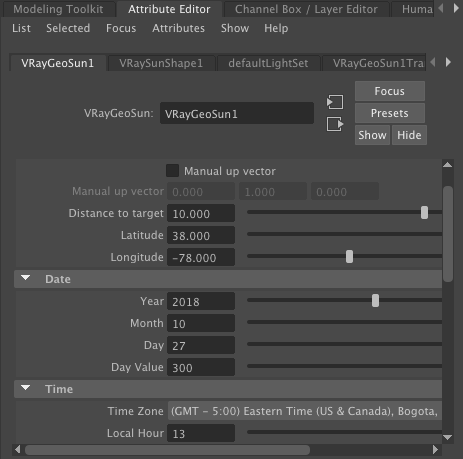
Once the sun is placed in the Maya model., Set the V-Ray sun position's geographical locations as:
Latitude = 38
-Mid Atlantic US
Longitude = -78
Time Zone GMT - 5:00 - US East Coast TIme
Local Hour 15 (3 pm)
Date: 11.27.2017
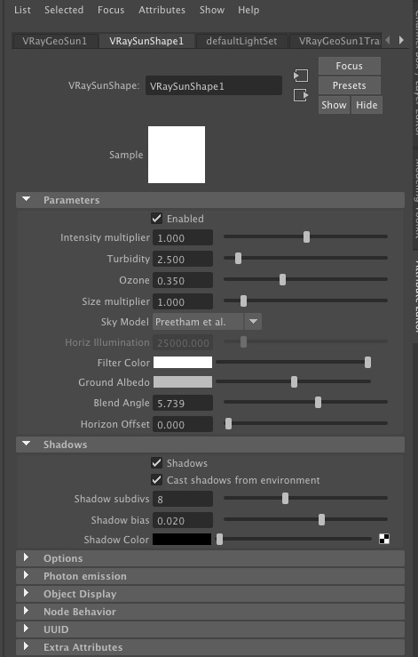
2. Under the VRaySunShape1/Parameters tab, set the sky model to Preetham et. al. and nder Ray Trace Shadow Attributes, turn on "Shadows" and "Cast Shadows From Environment".
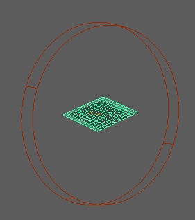
4. Optionally, add a point source light to the model from the light palette, 3rd icon from the left, to help with middle grey scale shading values.
![]()
5. Now add a polygon surface plane to the X-Z ground plane and subdivide it into 12 x 12 subdivision units in its "width" and "height" through the channels dialog box as done in prior workshops.
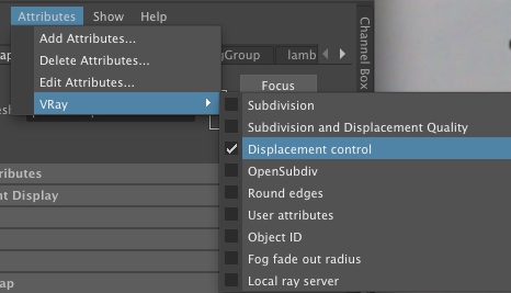
6. In the "planeShape1" tab for the polygon surface, right click on the "Attributes/VRay" menu at the top of the dialog box and add "displacement control".
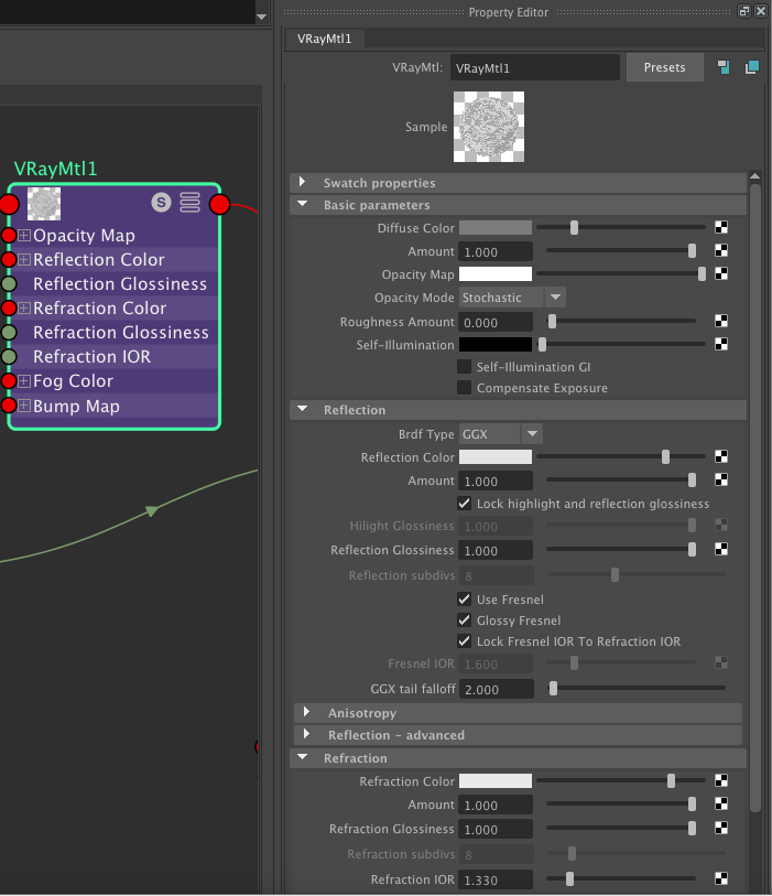
7. Within the hypershade panel create a VRay material that is a new, slightly dark gray, and also has a a mid gray reflection value and a light gray refraction value for a small degree of tansparency and refraction. Also, set the IOR (index of refraction) for the material to 1.35,
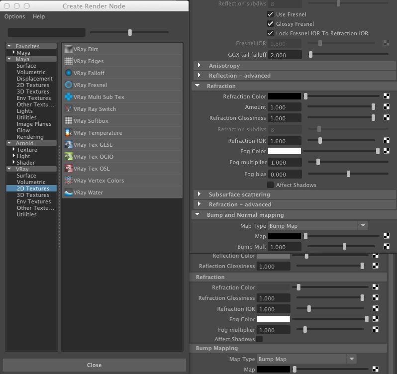
8. Continuing withing the hypershade window , open the bump map tab for the new material, and select the checkered box to the right pf the word "map".
9. Now, in the dialog that follows, select under VRay 2D textures option a VRay water material.
10. Applying the water properties as a bump map and adjusting its paramters, the original VRay material is modified as in the following sample.
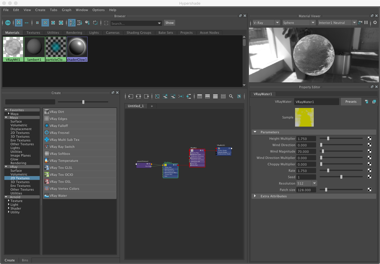
From Chaos Group's documentation, the following are the definitions for each parameter:
Height Multiplier – Specifies a scale multiplier for the whole texture.
Wind Direction – Specifies the wind direction and thus the direction of the waves.
Wind magnitude – Specifies the strength of the wind creating the waves. Higher values produce larger waves.
Wind Direction Multiplier – Specifies a multiplier for the importance of the wind direction. Smaller values will produce more variation in the direction of the waves.
Choppy Multiplier – Specifies a multiplier for the choppiness of the waves. Higher values will produce sharper looking waves.
Rate – Speeds up or slows down the movement of the waves. This value has effect only in an animation.
Seed – Specifies an integer used to set the starting point for the random generator. Different values produce different waves randomly.
Resolution – Specifies the amount of detail in the generated map.
Patch size – Specifies the real world size of one patch of the VRayWater texture outside of which the surface is perfectly periodic.
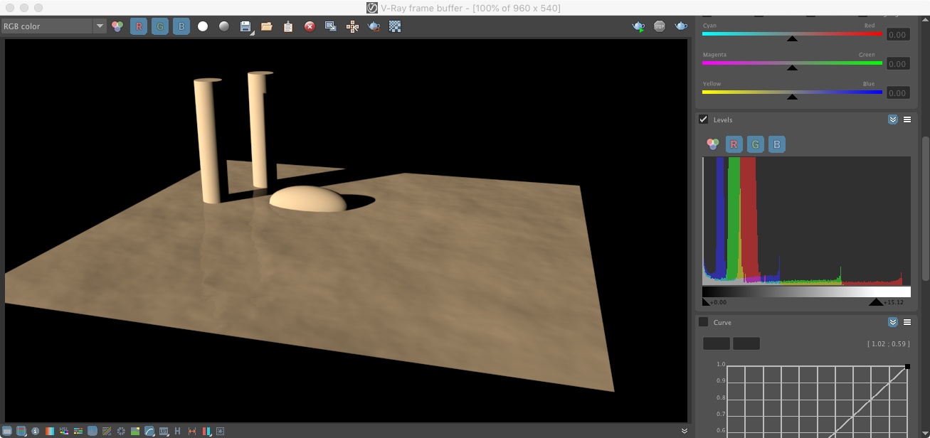
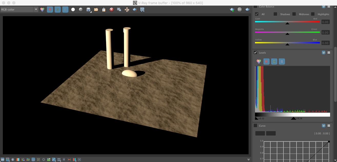
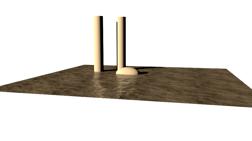
11. Add an ellipsoid and two cylinders, render in Vray and adjust the "Levels" according the procedure done in Part I of these notes. Due to sun color temperature the initial rendering of the the ground surface is a bit yellow. However, futher integrating the VRay sky and other environmental features will alleviate this. Moreover, the water material is an animated map that will cause the effects of water movement in the surface when the scene is animated.
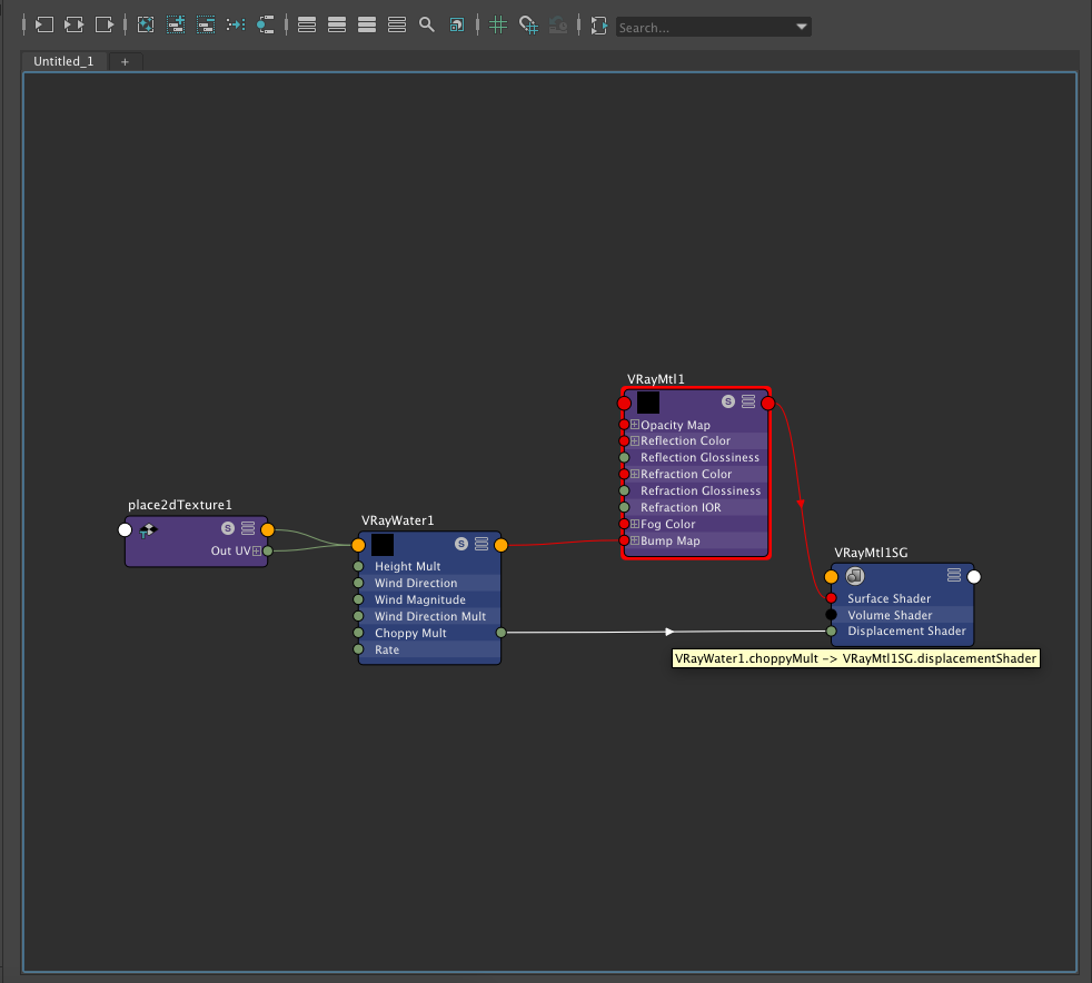
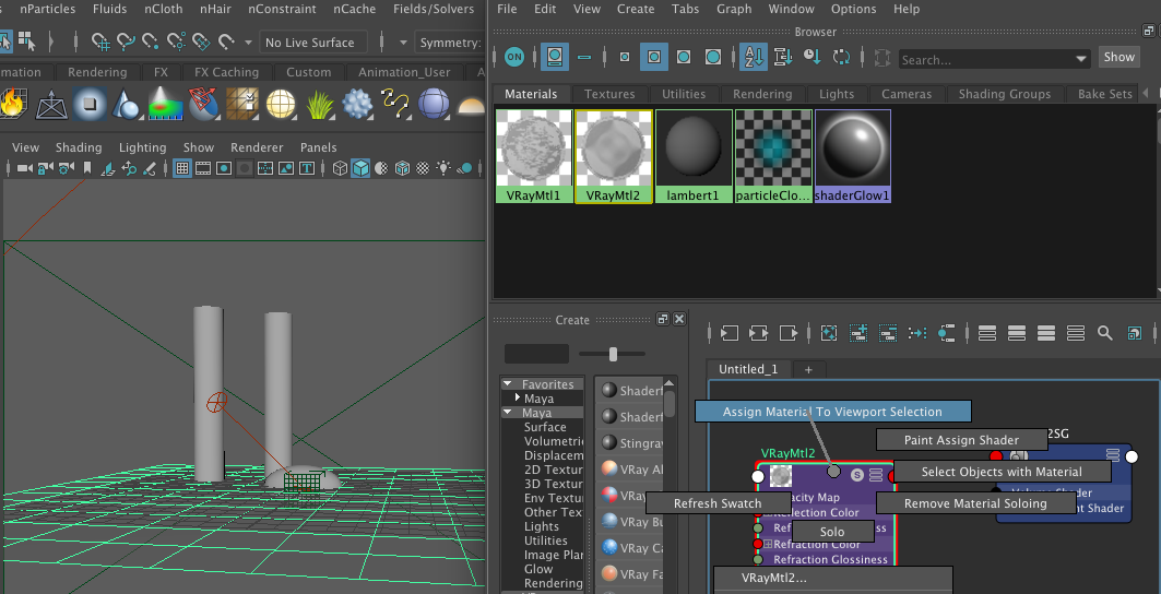
12. Continuing within the Hypershade Window, connect the output of the material VRay water into the "Displacement" port of the component "VRayMtl1SG" of the original "VRay Mtl" shader, and note that the rendering of the water level appears to change height accordingly.
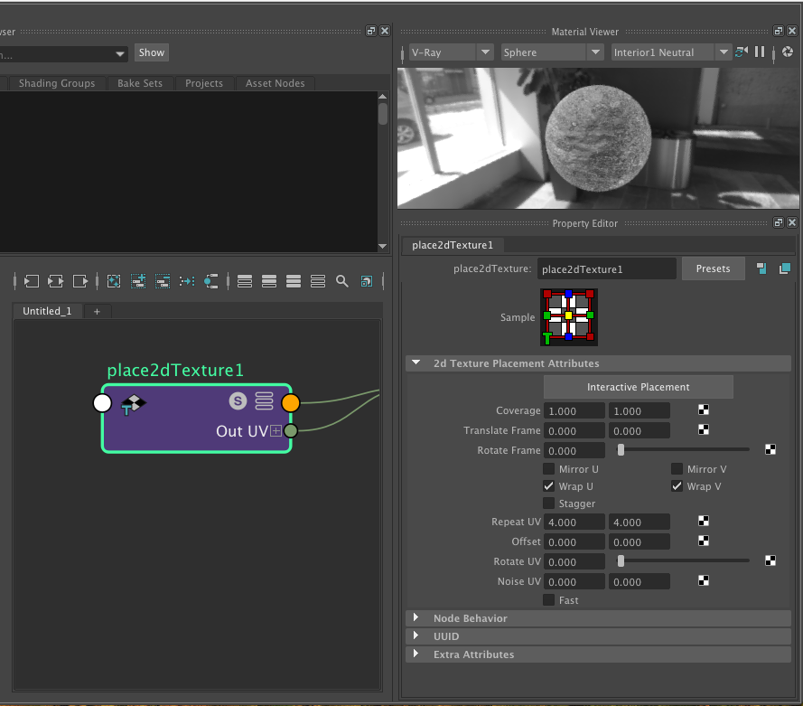
13. Returning the shader for the water, increase the density of the texture map to "Repeat U V" 4 x 4 times.
14. To add a sky, Go to the view menu, camera attribute editor, and select the environment tab.
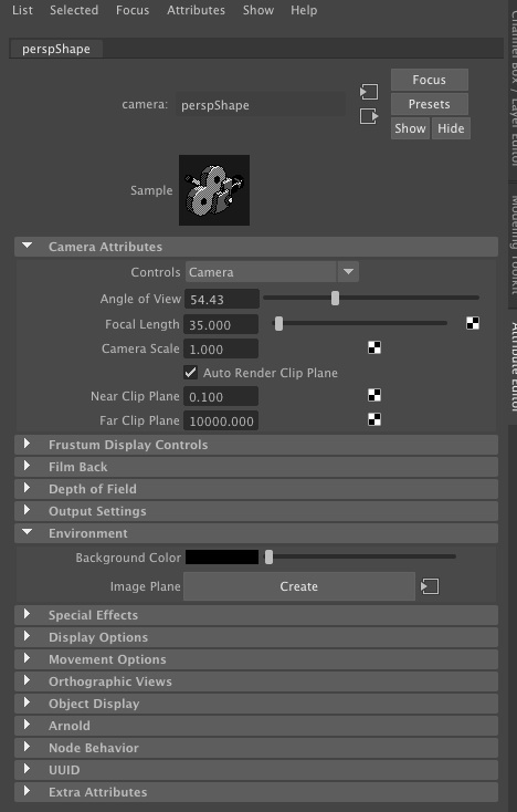
15. Select the "Create" button shown in the illustration above, and within the dialog box the follows, choose type "texture".
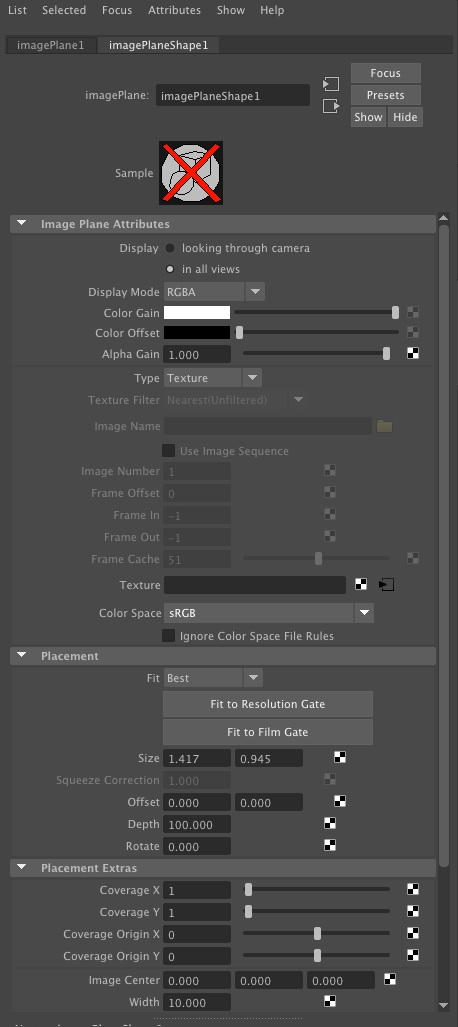
16. Select the checkered box adjacent to the word "Texture" and then uder the VRay shader options choose a VRay sky (alternative to the Maya sky).
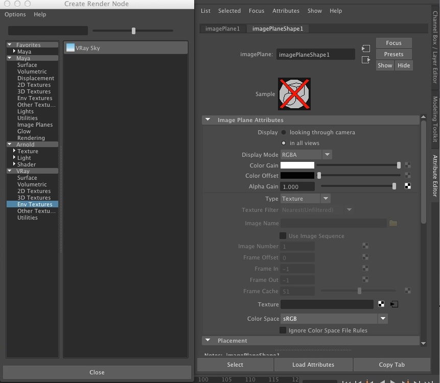
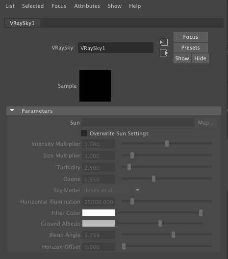
17. In the dialog box that follows, we see the VraySky in the attributes editor. Do NOT check the box that says "Overwrite Sun Settings", and the sky will inherit the values of the Sun light created in step 1 above.
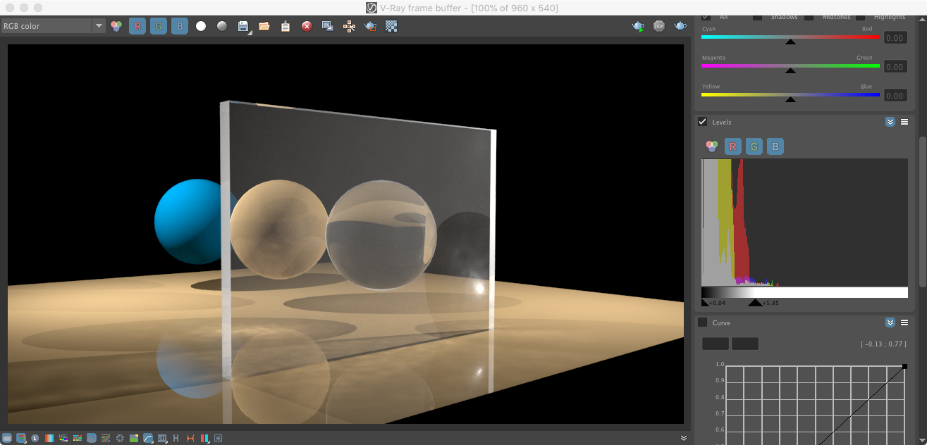
18. Next, render the scene in the V-Ray Render Buffer. Here the sky appears too bright and the water surface is still brownish reflecting the color temperature of the sun.
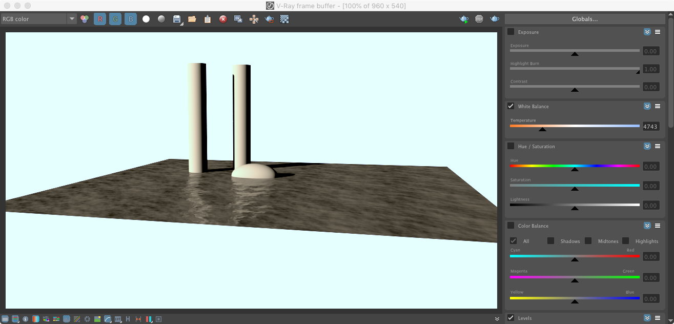
19. However, expand the VRay Frame Buffer Window by selecting the icon in its lower left-hand corner. In the expanded dialogue box on the right-side, select on the option for "White Balance" and move the slider to the left (or right) until the color of the columns, which should be white, turns white. This is the equivalent of correcting for color using a "White Balance" on a real camera which is a way to adjust to color temperature of the exposure. For more details on working with the V-Ray Frame Buffer see this link on V-Ray Color Corrections. Rendering again will result in a corrected color balance.
20. Change the diffuse color of the water matarial to a darker shade of gray. In addition adjust the refraction IOR to 1.33, the standard value for water.
Reset the V-Ray sun time to 13 hours (1 pm) on October 27th for a time of day when the sun is higher in the sky.
Re-render from a lower camera angle and see the result.
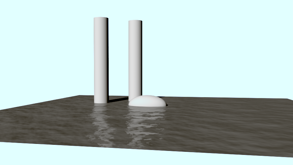
Re-adjust white balance and adjustments for "Exposure", "Highlight Burn" and "Contrast" in the dialog box at right in the image below.
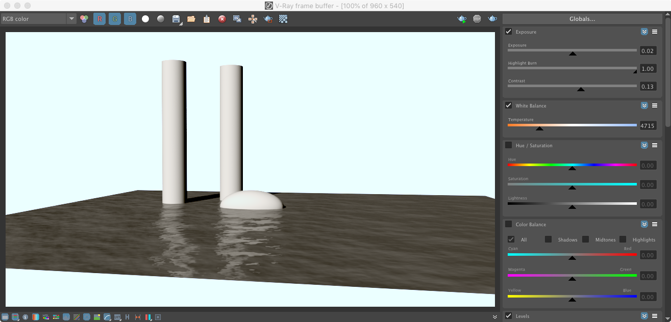
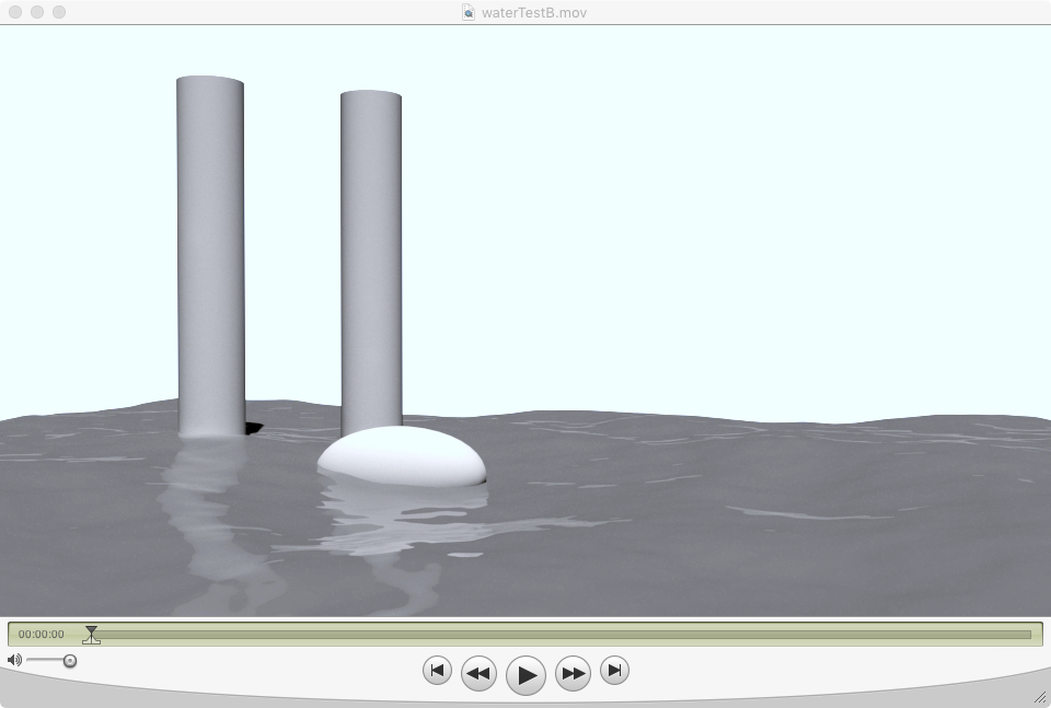
Select the following image to see a brief animated video clip.
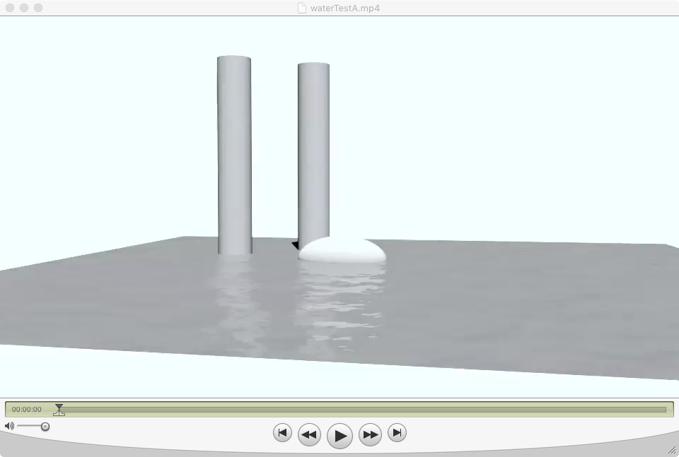
20. The renderings above use a "bump" map approach where water waves are rendered to appear to be 3D though a shading artifice but the underlying 2D geometry of the flat plane isn't changed. Alternatively, a "displacement" map creates more directly a rendered true 3D geometry that occludes other geoemtry and casts real shadows. This is possible by modifying the VRay attributes of the polygon plane such as illustrated in a tutorial posted on the web site http://www.grinning-tiger.com/.
21. Yet another method for a true 3D displacment is described here.
First, create a new V-Ray material with the same settings for Diffuse color, Reflection and Refration used previously, except do not create a Bump map.
Apply the new material to the water plane.
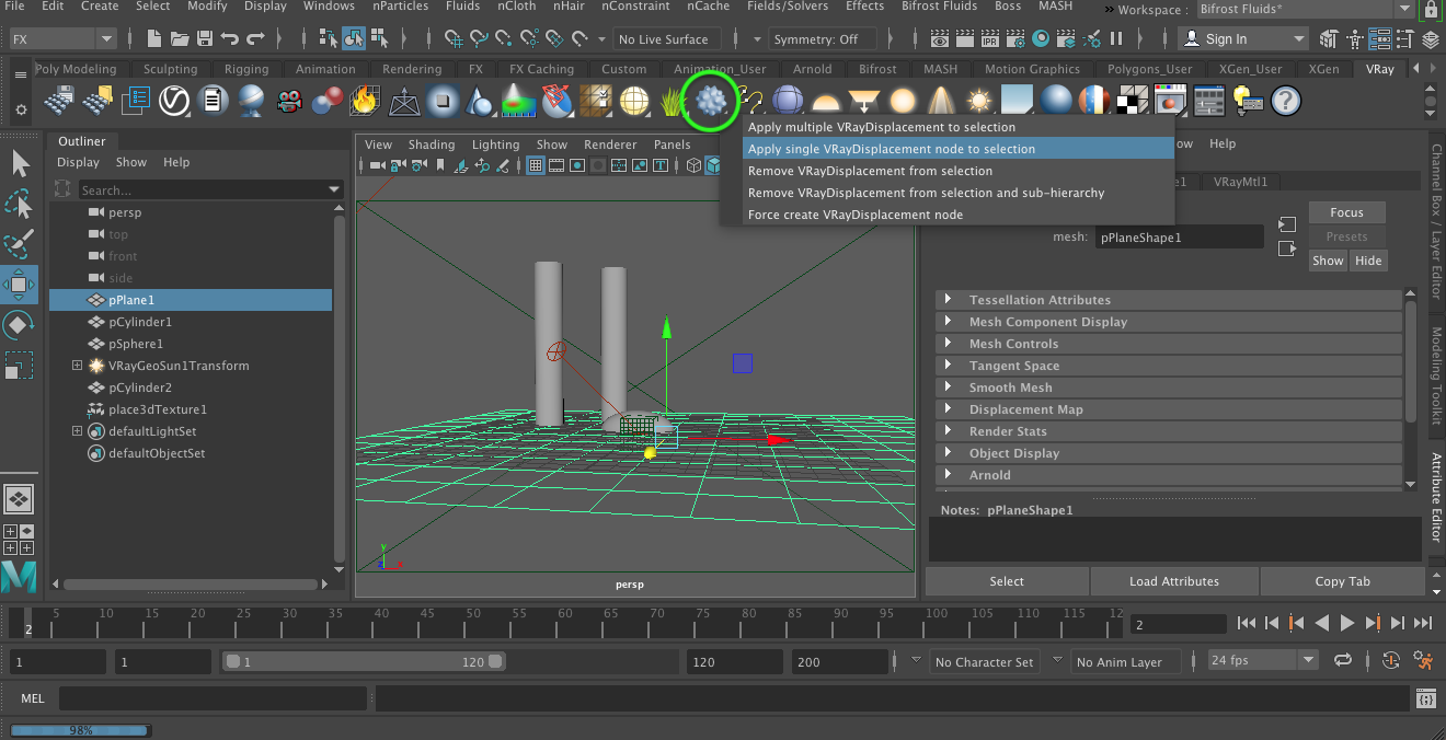
22. Next, begin by selecting the plane used to represent the water, shift-select the VRay Displacement Node from the VRay palette, right-mouse click on the the node and choose the option to "Appy single VRayDisplacment node to selection".
23. Next, within the " dialog box at the right, select the checkered icon and then the "VRay Water" animated texture utility.
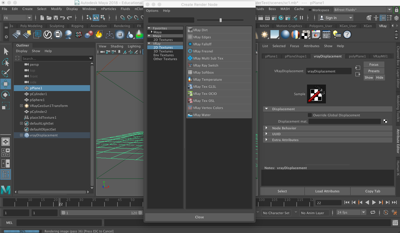
The last step in turn creates a second "VRayWater" texture. We will use this texture to replace the one that had been used for the water wave in the 2D bump map approach used previously.
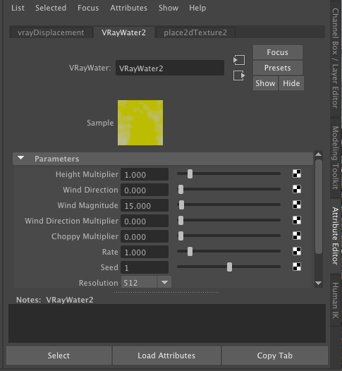
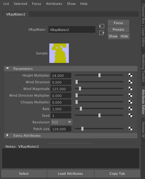
Change the parameters in the new VRayWater2 as indicated below.
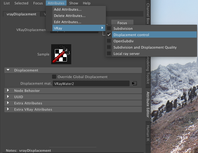
24. Within the Attributes dialog box for the vrayDisplacement, turn on "Displacement control".
The vrayDisplacement displacement feature results in the following more complete 3D water surface that occludes part of the cylingers and the ellipsoid object.
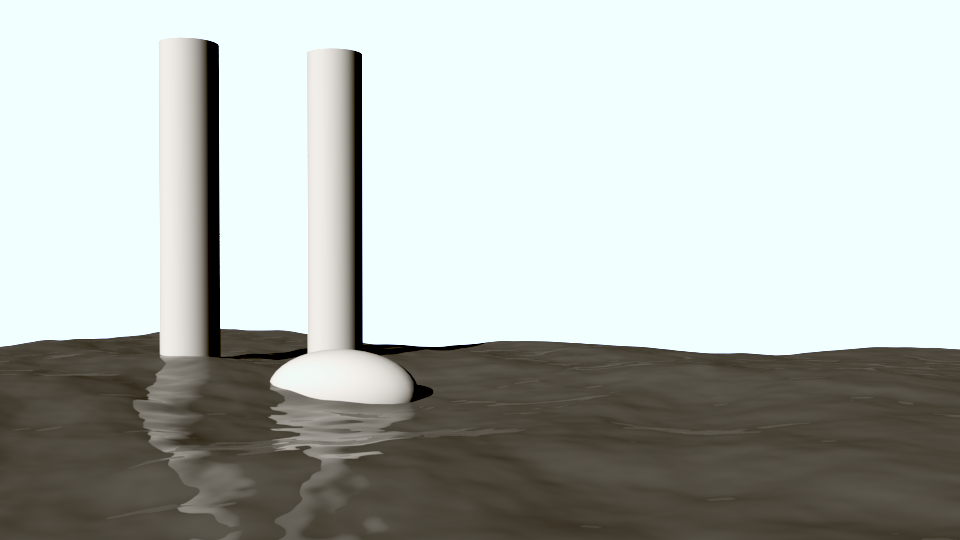
Select the following image to see a brief animated video clip for the displacement mapped waves.