September 23, 2021 Workshop 7 Notes
LIGHTING
AND MATERIALS, MAYA SOFTWARE RENDERING OPTION
This
workshop is developed after techniques described in the
Robinson text,. it contains examples that are reinforced by background
concepts in
Chapters Chapter 14 + Chapter 15 (part), pages 349 402
1.
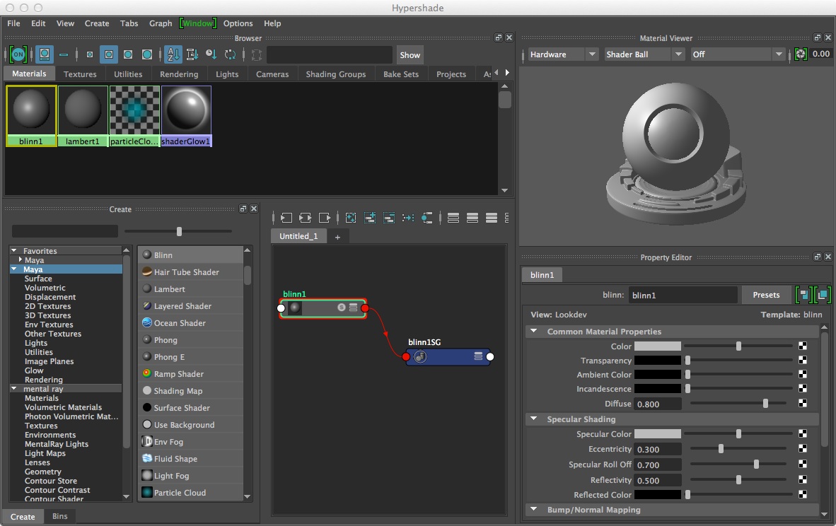
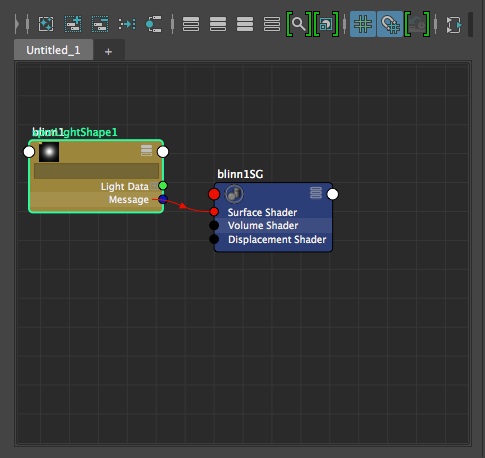
Shaders in Maya are based upon standard rendering algorithms and
include the following types:
- Lambert – flat
– cosine shading
(Lambert’s law)
- Phong – typical
phong (spectral highlight)
- Phong E – spectral
highlight in white
- Blinn – metallic
objects
- Anistropic – good
for material with grooves
- Layered Shader –
more than one material
- Ramp Shader – ramp
color (eye ball)
- Shadows …. Map of
shadow lines from viewpoint of
light sources (geo calculation)
These
types of shaders are acessible
through the hypershade dialog box or Window/Rendering Editors/Hypershade
2.
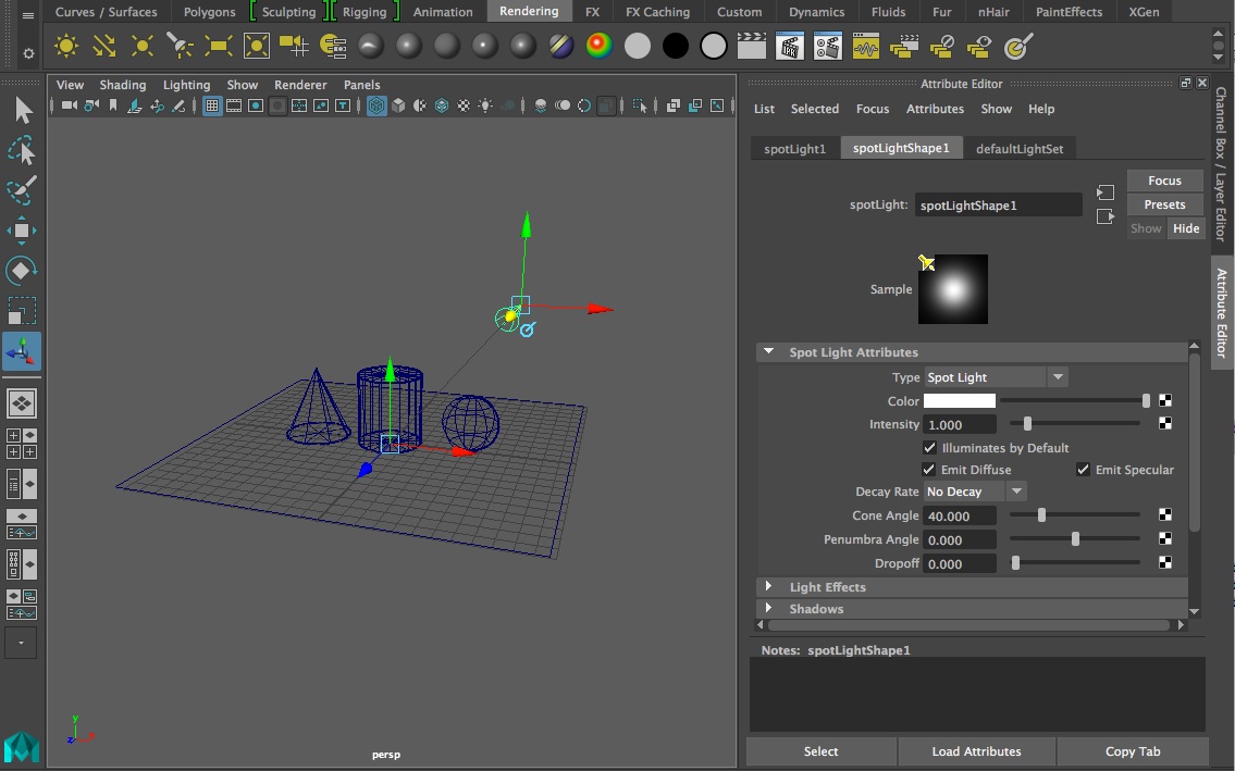
Lighting types & 3 point
lighting - Chapter 14
Lighting
types commonly used are 1)
Ambient, 2)
Distant/Directional, 3) Point and 4) Spot Light which appear from left
to right in the Rendering Shelf tab in Maya. Ambient light provides
general background illumination. A Distant/Directional light provides
parallel light rays from a specific angular orientation, and may be
used to mimic such distant lights as sunlight or moonlight. A point
light is an omni-directional light that sends light out in all
directions from a single location. A directional light sends light in a
specific direction at a specific angle from a source location to a
target location.

Key and
Fill Lighting: A typical three
point lighting
setup has a Spot light (also known as a Key light) to the upper right
of model at full intensity to provide high contrast shadows, a Point
light (also known as a fill light) to the upper left of the model at
lower intensity filling in middle gray values, and a back spot light
(also known as a back key light) at lower intensity than the front spot
light and that provides some three-dimensional depth to the
rendering.
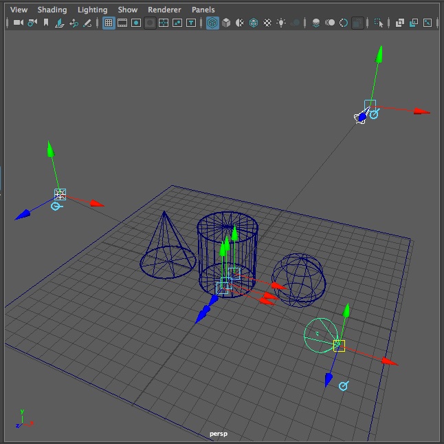
Key light
set at full intenstity and
positioned using
the show manipulator tool (selected tool on left-hand side of
Application window).
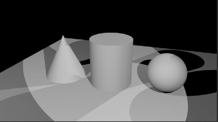
Full three point lighting setup and rendering. Back key light (spot
light) being set into place on left. Rendering on right.
3.
Materials Some Definition of Textures
and Methods
Materials
reference attribute nodes that
determine look of an object. This includes
Texture
– an
material that is mapped to object
Types: procedural (based on
an algorithm) and
image (based on a
photograph).
Bump Map
– image read for its
gray scale value that makes a material have the appearance of a surface
relief
4. Menu
items in Hypershade window (Left
to Right)
From left to right the icons above the work area window (see above) have the following functions . Ignore for now those functions which are grayed out:
Clear Graph bar – clears out any nodes in work area
Add selected nodes to graph
Remove selected nodes from graph
Rearrange graph
Clear graph materials on selected objects
Hide attributes on selected nodes
Show connected attributes on selected nodes
Show primary attributes on selected nodes
Show attributes from custom attribute view
Toggle the display of attribute filter field
Toggle the icon swatch size
Turn on grid in graph window
Turn on gravity grid in graph windows
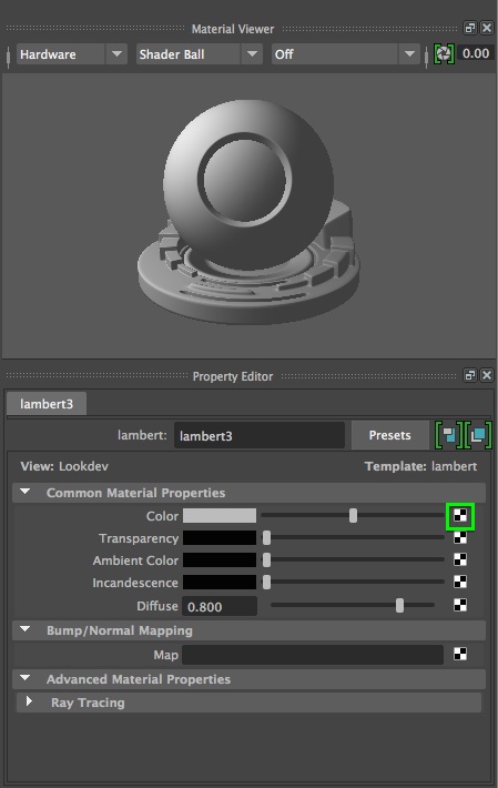
5. Basic
material properties:
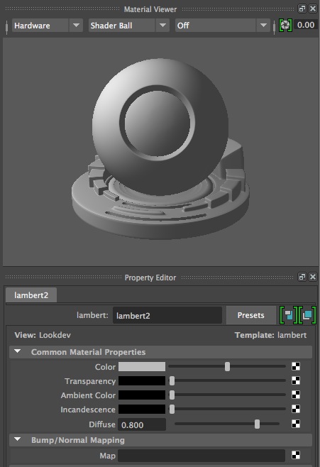
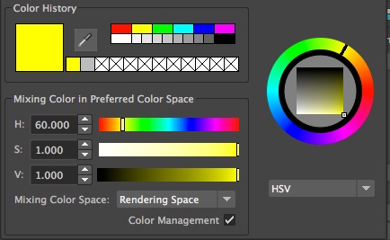
Color
– RGB or HSV selection
model color
Transparency – degree to which material is transparent
Ambient Color – brightness or darkness of whole material
Incandescence – create appearance of giving light
Bump mapping – makes a surface appear bumpy
6.
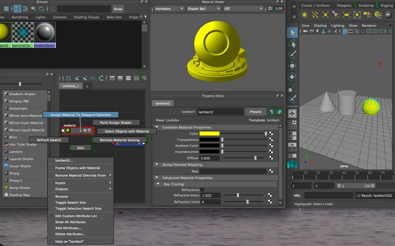
Example of use of simple material
definition and assignment
Change
color of an object
- from Windows menu select
Rendering Editors ->
Hypershade
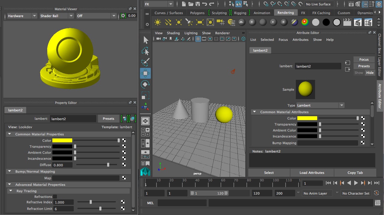
- Select create materials
- Click Lambert (cosine shaded
object)
- Double click the new
material to invoke attribute
editor
- Select field next to color
on right-hand side of screen.
- Choose color from rgb or hsv
model/accept
- Drag material with middle
button onto surface from icon in
work
are to object. Or select surface and select material with right mouse
button, select “Assign Material to Selection”
6.
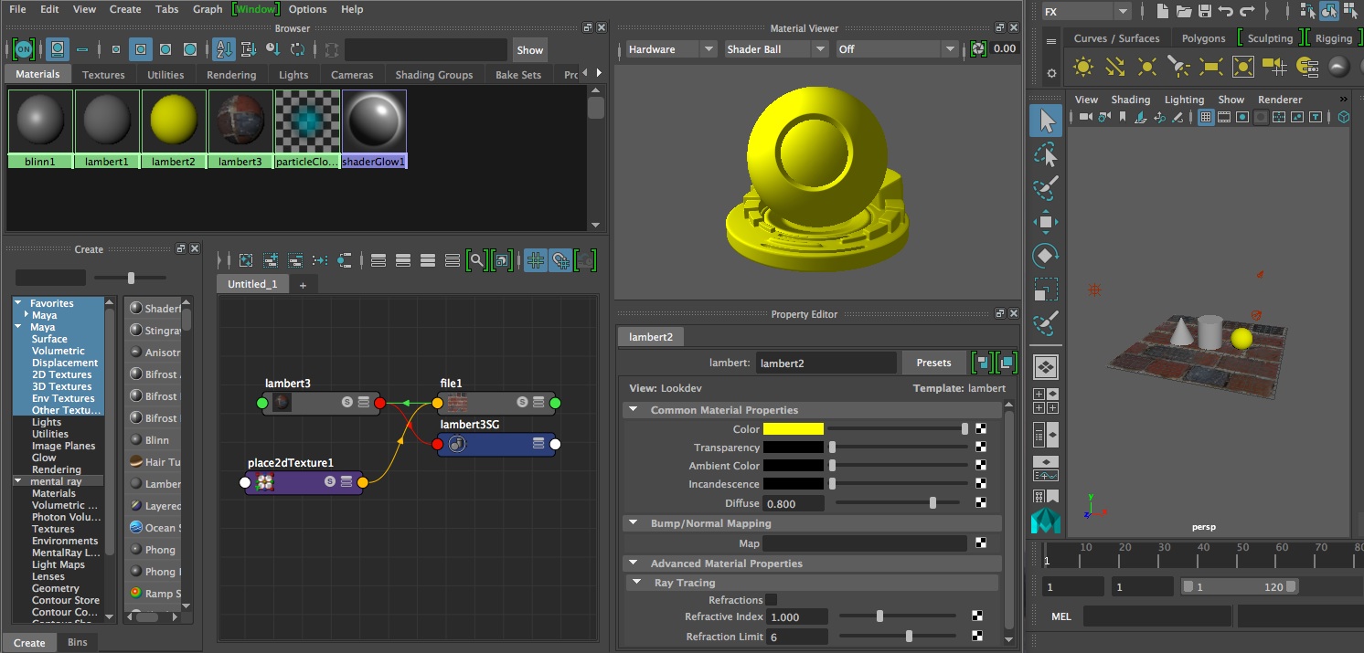
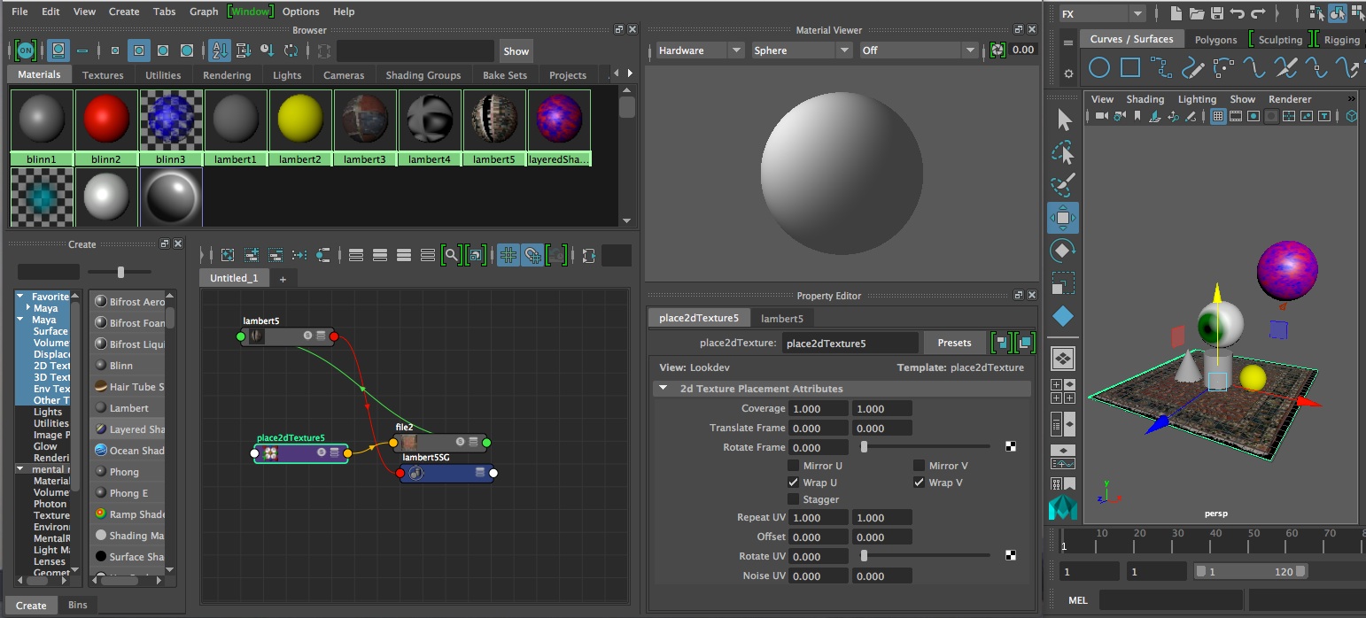
Texture mapping nurbs surface
Prepare
brick.jpg file or somephoto.jpg
file. Make a
material from a lamber shader. In the color selection area on the
right-hand side of the the screen, select the checkered
symbol
and follow the dialog box to load the brick.jpg file.
Once
the image
map has been loaded into the definition of the material, it is included
in the symbolic graph of the material (left-hand side of image below).
Double-clicking on the Place2D texture tool activates interactive
placement options.
- Nurbs surfaces U horizontal
– V vertical map from
lower left corner to upper right
- Can map TIF, JPG and
Maya’s IFF
- Create Lambert material
- In Hypershade panel double
click on icon.
- Add brick file to material
- Select object, right click
on lambert material and assign
to object.
- Double click on
pace2dTexture node
- See red square on object:
middle mouse button - drag center
to move, drag corners to rotate,
- Repeat UV … to
repeat pattern (do 4 in each of U
and V)
7. Ramp
texture (eyeball)
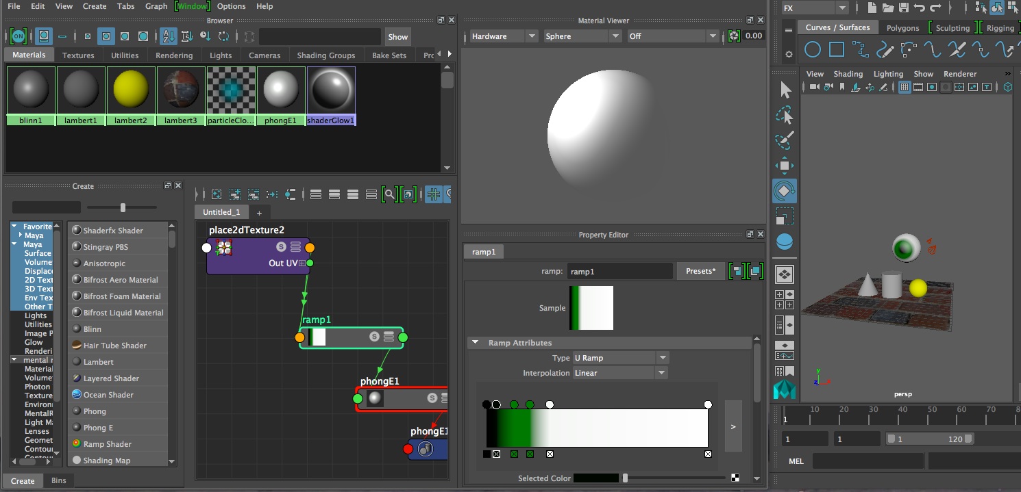
- Create Phone E shader
- Double click on the icon
(gets attributes window), and then
click checkerboard icon on the color.
- In response to the dialog box to "Select a Render Node", select a "ramp" shader.
- Change top shader to black
by lowering color solider to
left.
- Move middle shader (default
color is green) closer to top
- Click
on ramp 1/5th way to bottom,
place new position indicator just below 2nd one (above).
- Click
and drag bottom indicator just
below new one (3rd one).
- Click
on color swatch for above
indicator and select white.
- Change
shader type to U Ramp if needed (rathern than a default V Ramp)and
assign to sphere (in Maya 2018 it appears that you may need to try using a Type V Ramp and a type U Ramp before detemining which type is more effective).
8.
Layered Shader
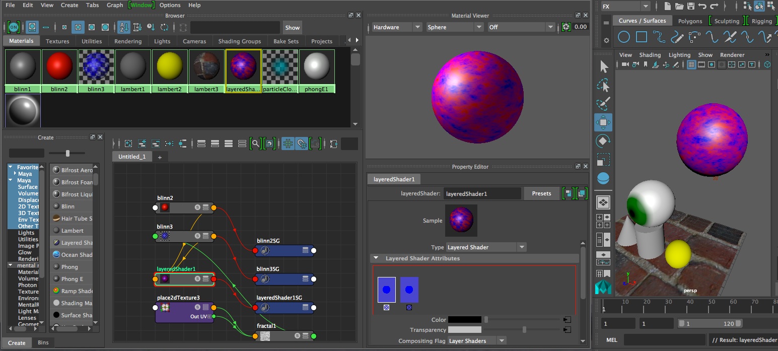
- Create
two blinn shaders red and blue.
- In
blue shade, double clock on icon,
and then on transparency color select fractal.
- Create layered shader
- Double click on layered
shader material.
- With the middle mouse button drag blue and red materials
from the Hypershade into the red
square under Layered Shader Attributes. (note blue shader comes before
red shader)
- Click X under original green
shader to remove it.
- On blue blinn shader, use
fractal to define transparency
- Apply the shader to a sphere.
- In Render view, click on the
Redo Previous Render Icon. Red
can be seen through the blue due to fractal transparency.
9. Bump
Map
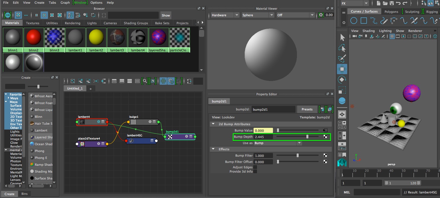
- Create Lambert
ahder and assign to plane via MMB.
- Double-click on Lambert
shader
- Click map button next to
bump mapping and select bulge.
- Select render icon (upper
right hand side of screen) to see
bump map..
- To change bump depth/chose
graph materials on selected
objects icon in hypershade panel and select lambert object.
- Select bump2d node, increase
bump depth , & render
(render icon)
10.
Projection Map
- Create NURBS plane.
- Create a lambert material in
Hypershade and apply to plane.
- Double-click on the lambert
material in Hypershade
- In attribute editor, click
on map next to color slider.
- Click the file button
(select a file).
- Click file1 tab at top of
attribute editor.
- Click on folder icon next to
Image Name
- Open your own image.
- Goto perspective view and
select key #6 to render.
- Select the place2d texture
utility in the hypershade window/
- Experiment with rotate frame, repeat UV and
rotate UV options.
[If
surface appears to be moving through
texture,
then in Rendering mode, select the surface, and then from the Texturing
menu select “Create Texture Reference Object”]
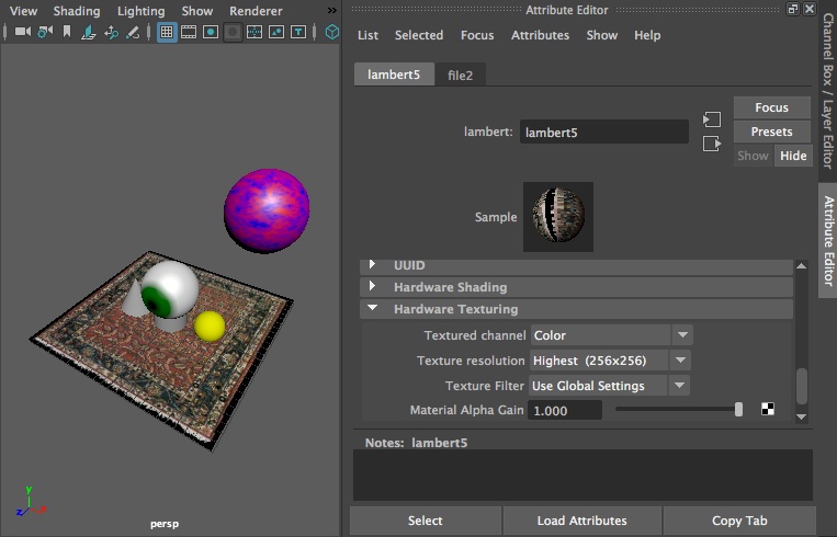
11. To
Improve Quality of Rendering
- Select object.
- In hypershade panel, choose
Graph Materials on Selected
Objects Icon.
- Double-click on the material
in Hypershade.
- In Attribute editor, under
Hardware Texturing, click arrow
to expand options.
- Change “Texture
Quality” setting to
High. Only do this for temporary viewing since it slows Maya down.
11. 3D
Paint Tool
- Create Lambert material and
assign it to a new NURBS sphere.
- Select the sphere.
- From Texturing Menu, select
box next to 3D Paint Tool.
- Scroll down until you see
File Textures.
- Click the Assign Textures
button, determine resolution, and
click Assign Textures {note project setup must include texture area
- In perspective view, hold
“b” key and
move mouse left & right to size brush.
- Click and drag on surface to
paint.
- Select swatch next to floor
color and choose yellow at top
of Color Choose.
- Click “Flood
Paint”
- Change paint color and paint
smiley face on surface.
- Click on the change brush
button, scroll down Visor and
select hair folder.
- Choose hair type and paint
on to sphere.
- Clear surface with flood
button.
- Select brush adjacent to
Artisan to return to normal brush.
- Decrease capacity of brush
to see color beneath
- Can edit image in Photoshop
directly from directory.
- [techniques can also be used
for Attributes and Transparency, pull-down menu under file textures.
12. VRAY Preview
Tutorials on VRay and Maya are published on the Chaos Group Web site. We will be exploreing VRay in the next workshop and it will be covered by workshop notes 8. This Chaos Group online tutorial primer is directly relevant to our needs.