September 30, 2021 Workshop 8 Notes
Introduction To Rendering With V-Ray
V-Ray is an implementation of a Global Ilumination light energy modeling method that is based upon realistic simulation of lights and materials and takes advantage a probabilistic sampling to reduce the level of computation time. The implementation within Maya allows for the continued use of some regular Maya shaders and also provides an additional set of V-Ray shaders with more advanced simulaation properties.
Tutorials on VRay and Maya are published on the Chaos Group web site. The primer is the most complete reference for our needs. The V-Ray tutorials are a good place to begin toexplore different materials and simulation methods.The notes here reflect a shorter and quick set of examples that help to establish a quick introduction, but the Choas Group web site is best for more thorough explanations and details.
As noted on the Chaos Group overview web site, the following Maya (non V-Ray) shaders are supported:
For these materials, the supported parameters are:
In addtion, the following Maya lighting types are also supported:
See the Chaos Group web site for an overview of V-Ray material shaders and V-Ray lights.
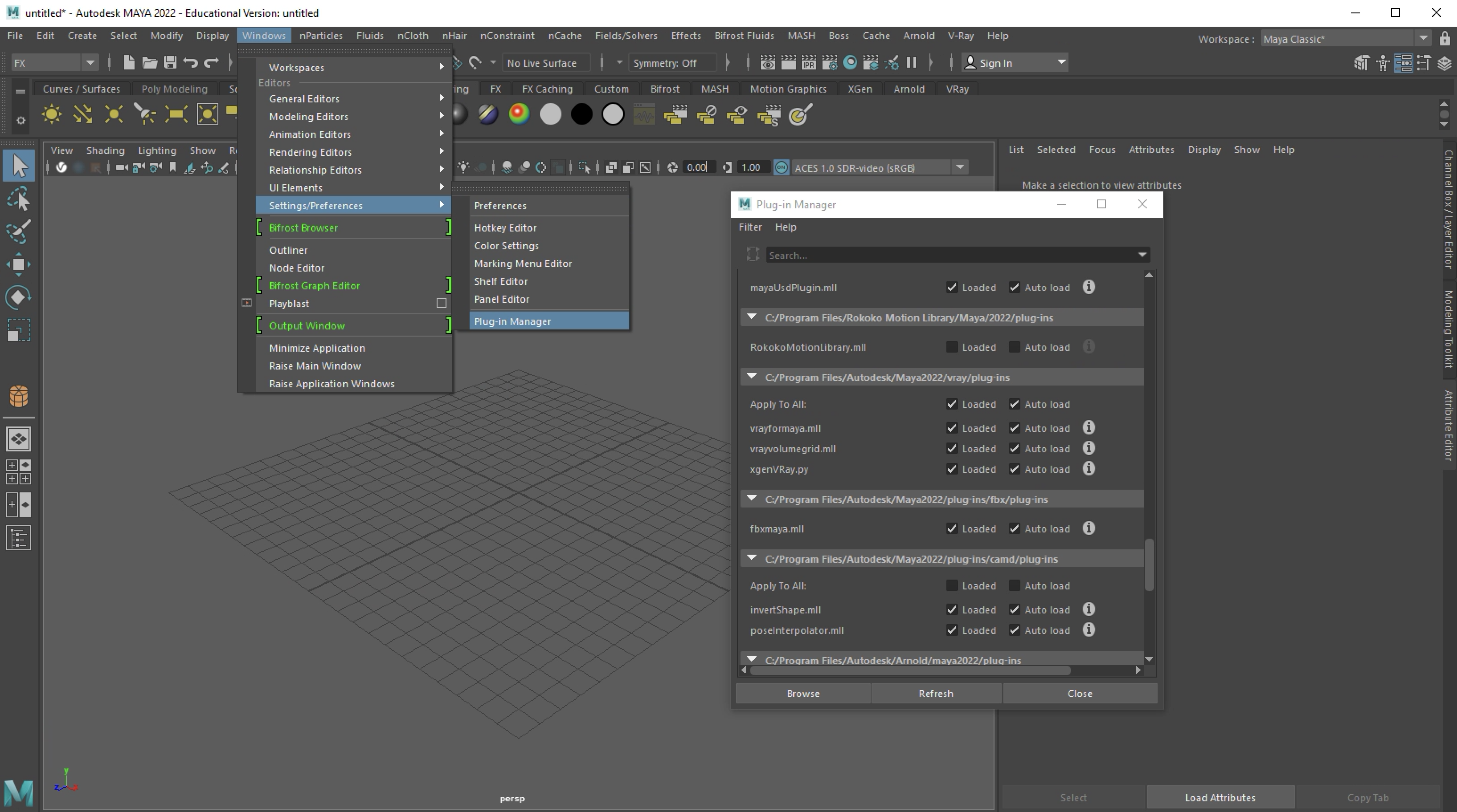
Once the VRay installer for Maya is loaded onto your computer, the first step is to activate it within Maya's plug-in manager. This is done through the menu sequence "Windows/Settings Preferences/Plug-in Manager" as illustrated in the image below. Within the "Plug-in Manager" select the "Loaded" check-boxes as shown and the select the "Refresh" button. This will activate Maya for the current work session. If you have administrative rights to the computer you are working with then you can also select the check boxes for "Auto load" and VRay will be active by default for all subsequent work sessions. Note that this means that it will also claim a portion of available computer memory and so you may want to avoid the "Auto load" option and activate VRay just one work session at a time.
In part I below, a few variations on basic VRay material and their properties are adjusted. The full set of options and range of values for this type material is expanded in detail on on Chaos Group web site. In parts II and III two methods of generating animated water waves are illusrated.
Part I: Vray Material Shader Example with IES Light
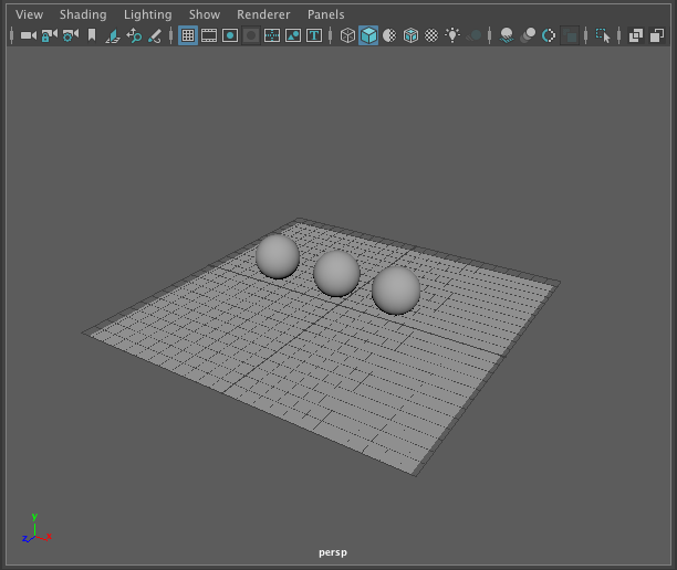
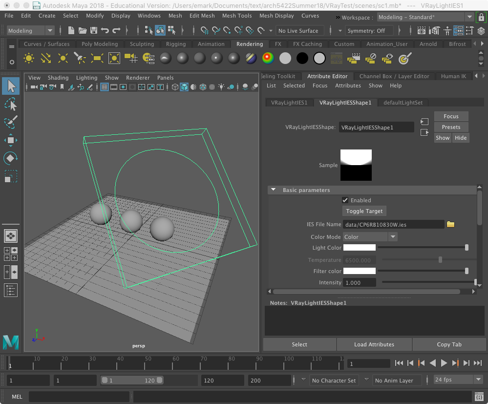
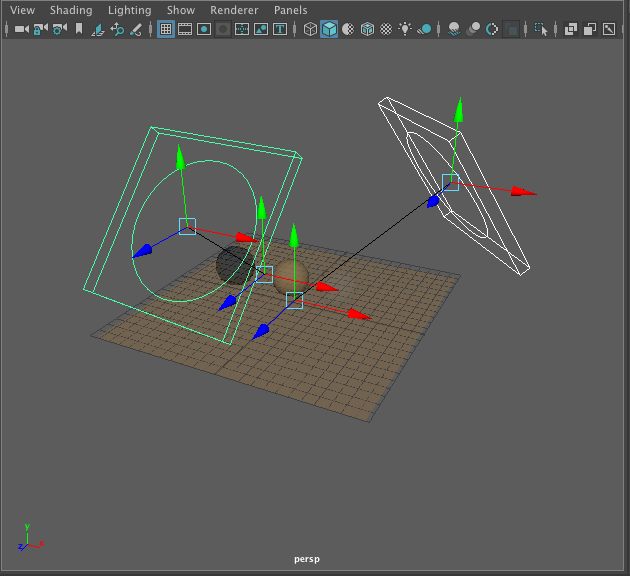
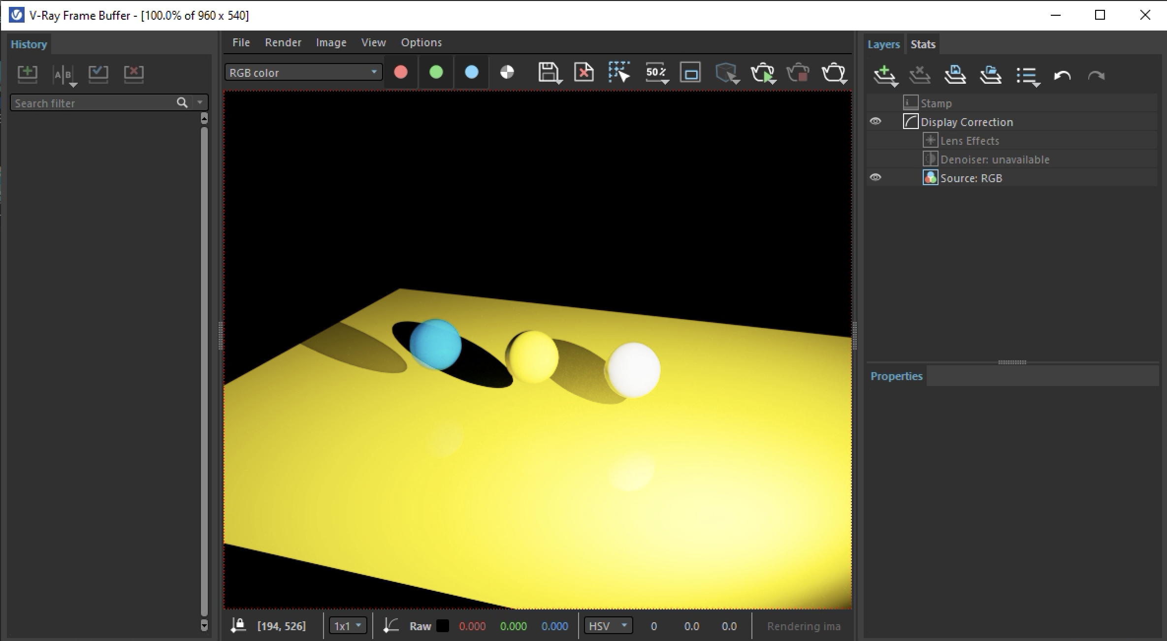
1. Create a project folder "VRayTest" and save a scene "sc1.mb". Next, create three polygon spheres above a polygon plane as shown below:
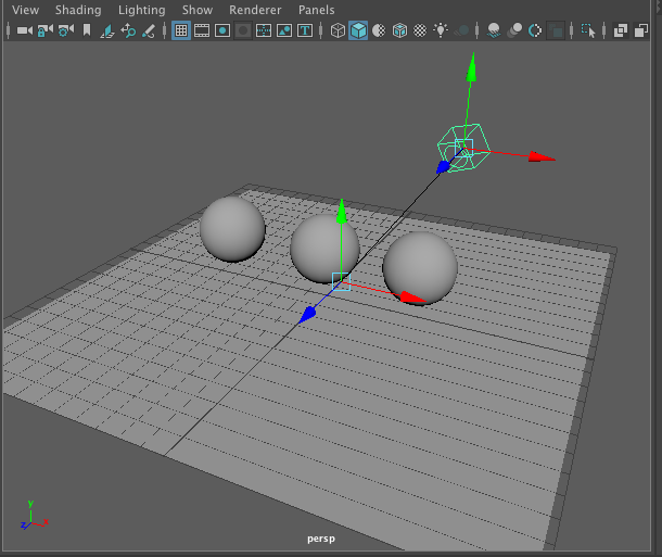
2. Go to the V-Ray tab, right-mouse click on the "V-Ray IES Light" symbol, second one from the the right-hand side of the light types, and add the light to the model space.
![]()
3. Until further notice do NOT use the menu item "Modify/Show Manipulator" tool to position V-Ray lights due to an apparent bug in the current beta release of the software. Use the move and rotate tool to position light above and looking down at the center sphere similar to how the technique was use used in previous tutorials with respect the spotlight for Maya Software.
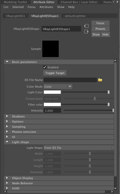
3. Open the properties window for the light and the tab "VRayLightIESShape1" as illustrated below. Next, open the sub-areas named "Basic parameters" and "Light shape" as also illustrated below. IES refers to Illuminating Engineering Society data that is typically provided by lighting manufacturers. Here we will use an IES data file CP6RB10830W.ies which holds data for the simulated light intensity and geometry profile for a Core Pro lighting fixture made by Phillips Lightng (see the original web source of the data file for addtional details).
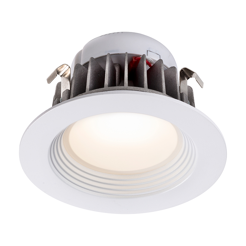
Core Pro LED Light by made by Phillips Lighting.
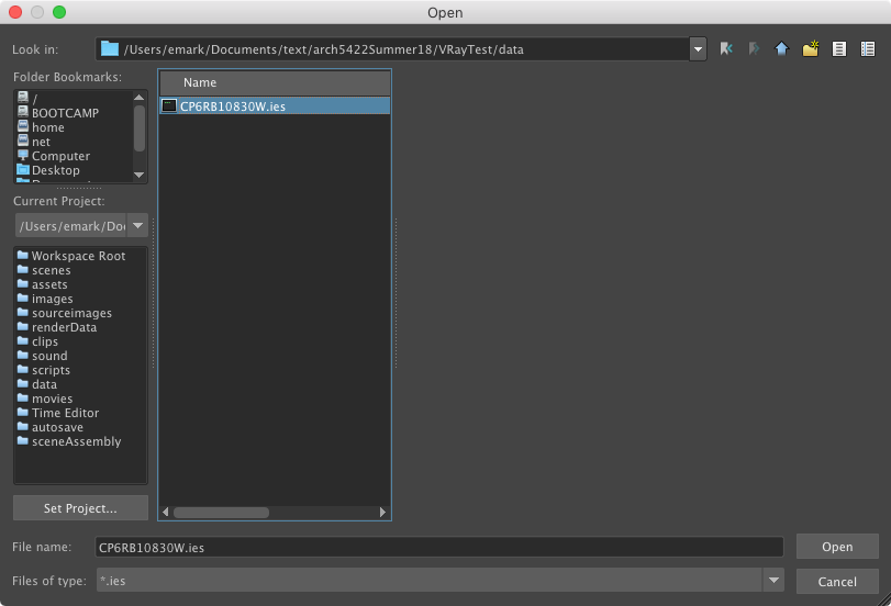
Download the file CP6RB10830W.ies and place it inside the "data" subfolder of the project folder.
Within the "Basic parameters" subarea, and adjacent to the "IES File Name" blank text field, select the yellow folder and then select the IES file CP6RB10830W.ies from the project "data" subfolder.
Once the IES file has been loaded, the view window in Maya will be changed to match the Core Pro lighting fixture.
4. Now, under the menu item "Windows/Rendering Editors/Hypershade" open the hypershade panel and review the
"Surface"
shaders available for V-Ray.
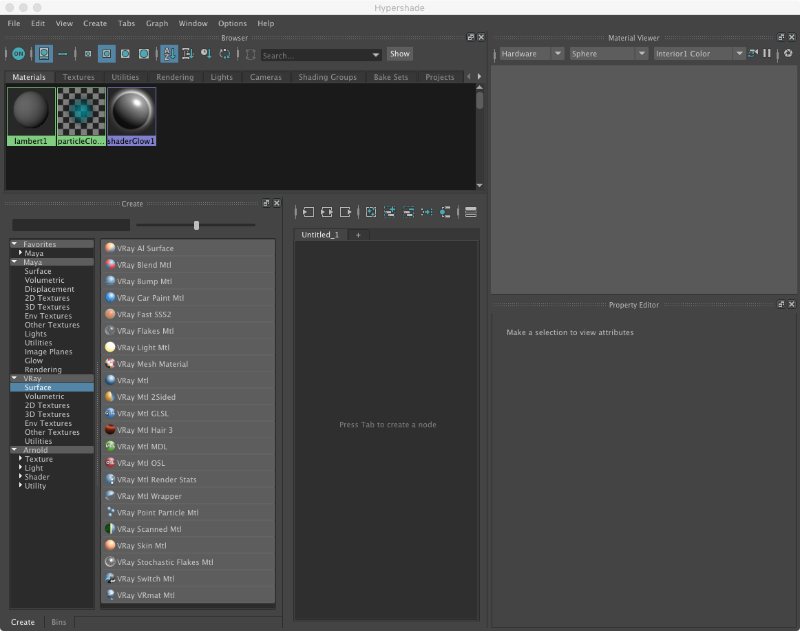
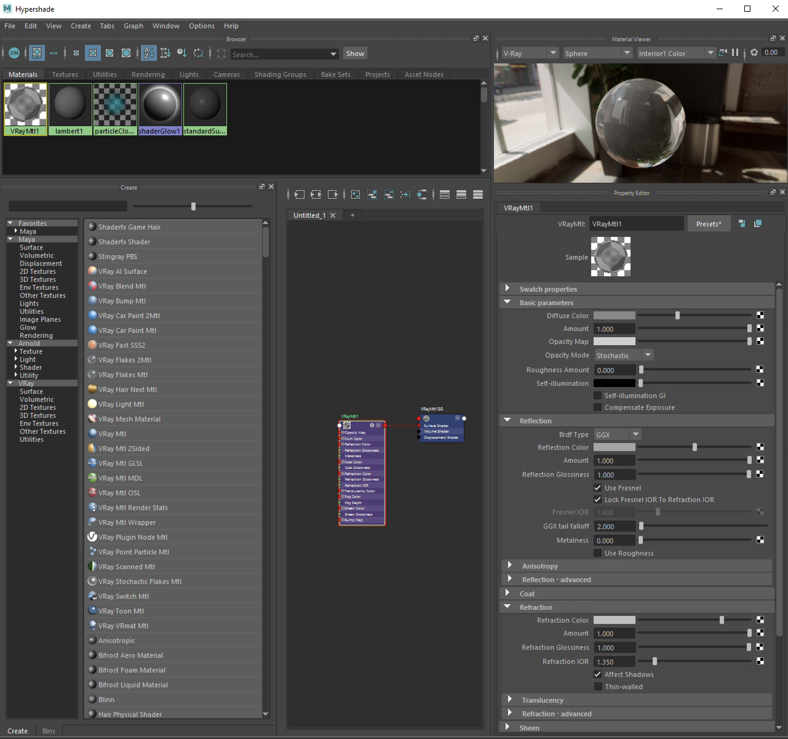
4. Select the generic type V-Ray shader named "VRay Mtl".
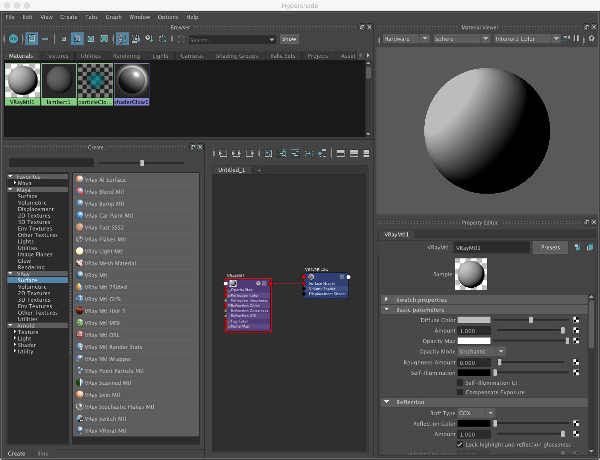
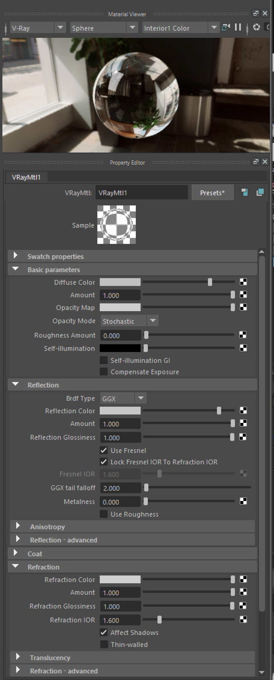
5. Within the property editor change the Material Viewer from "Hardware" to "V-Ray", and change the sliders for the "Diffuse Color", "Reflection Color" and "Refraction Color" to light gray as shown from left to right. These values moving from black to white in effect make the material less brighter, more reflective reflective , and more refractive with respect to the light amount passing through . Next, assign the shader to the rightmost sphere in the model. Note that the IOR (index of refraction) for glass at IOR = 1.6 is used.
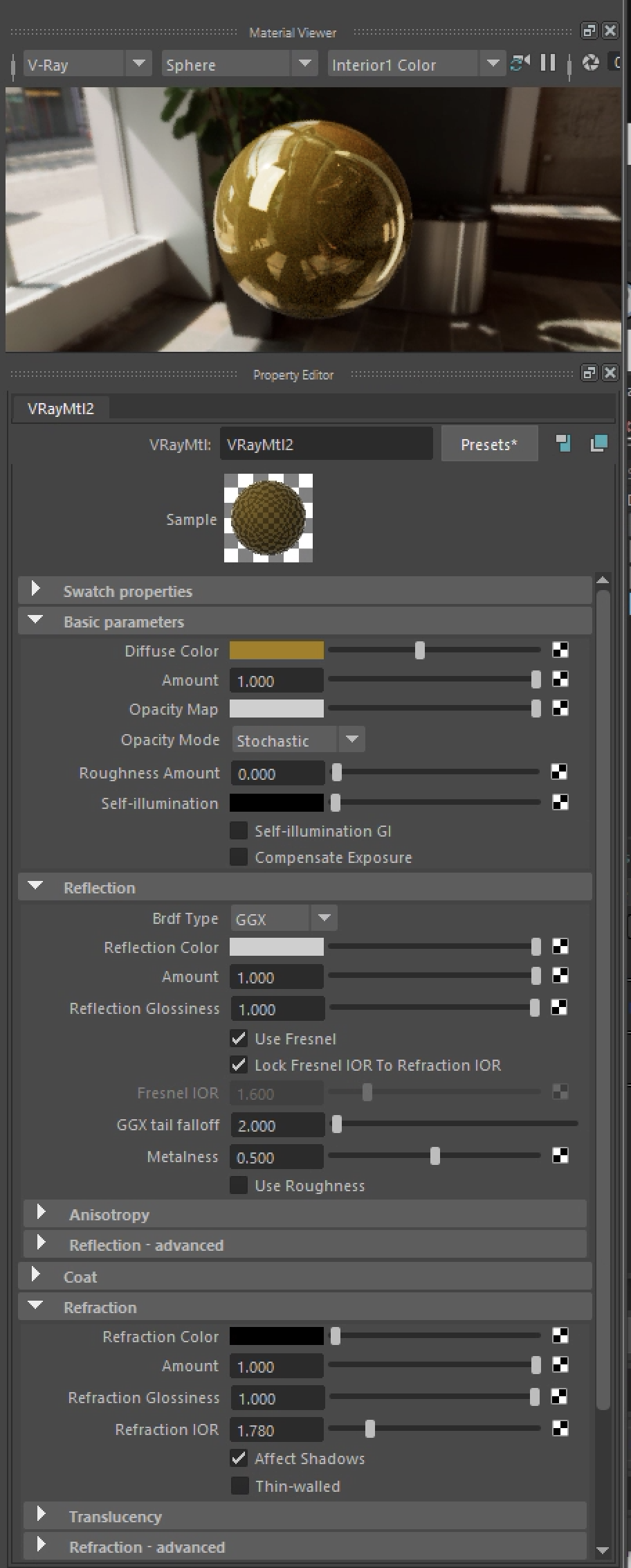
6. Create a second VRay "VRay "mtl" shader with the same properties, except let the "Diffuse" color have the appearance of "brass" or "shiny copper". Except, leave the "Refraction" color as black. Note that the "Reflection" IOR value is Locked to the Refaction IOR value of 1.78 a value presumd for copper . This controls refraction off the surface .vs. through the surface. An additional value for metaness is also set to 0.5. Next, assign the shader to the center sphere in the model and to the planar polygon.
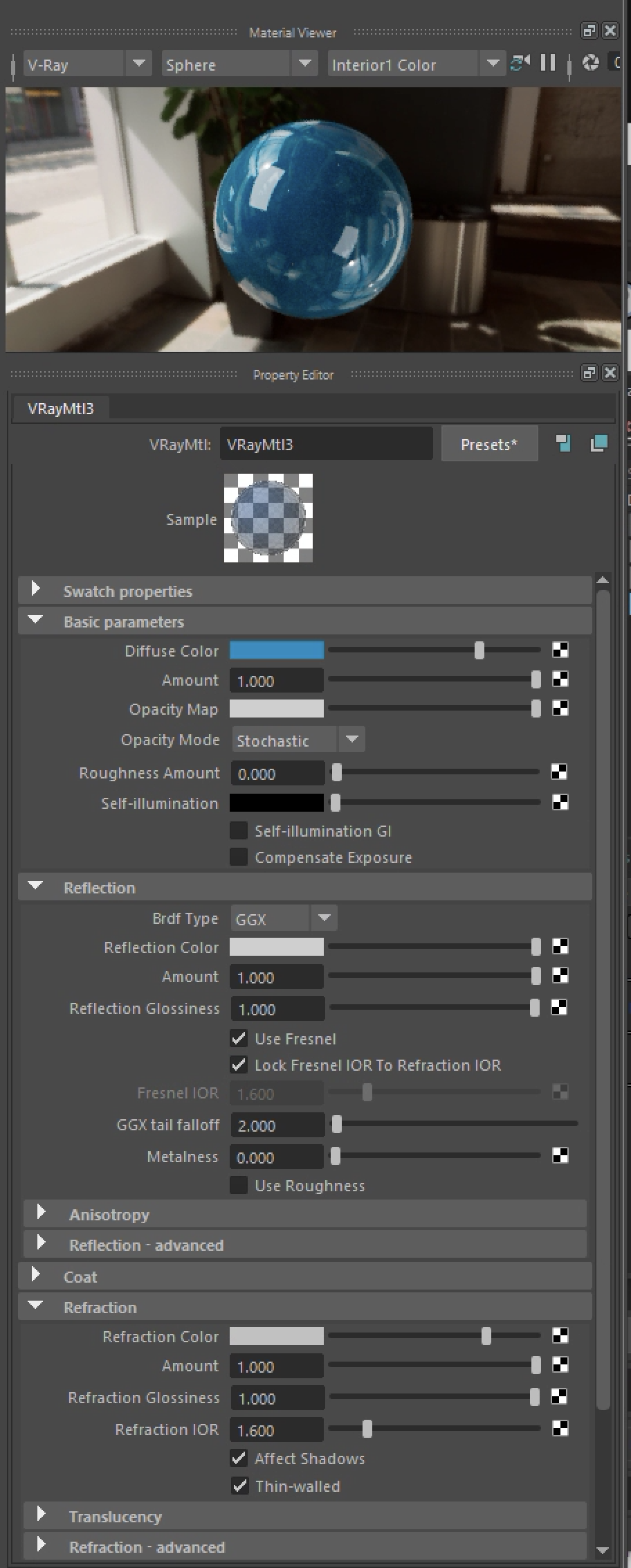
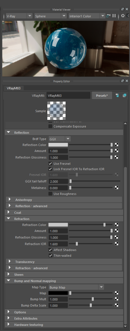
7. Create a third VRay "VRay "mtl" shader with the same properties as the first one, except that the diffuse color is close to cyan. Next, assign the shader to the remaining sphere in the model.
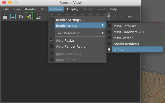
8. Next, open the "Render View" window, and go to the menu item"Opens/Render using/V-Ray".
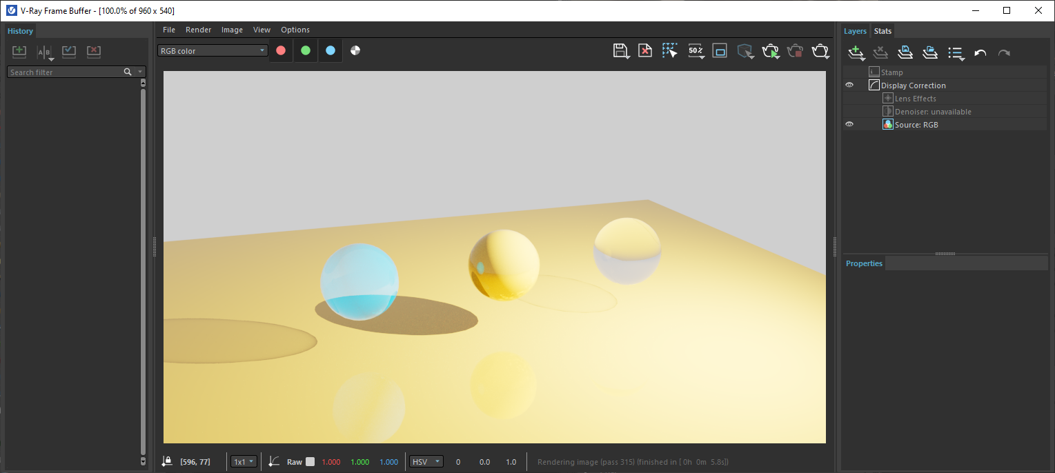
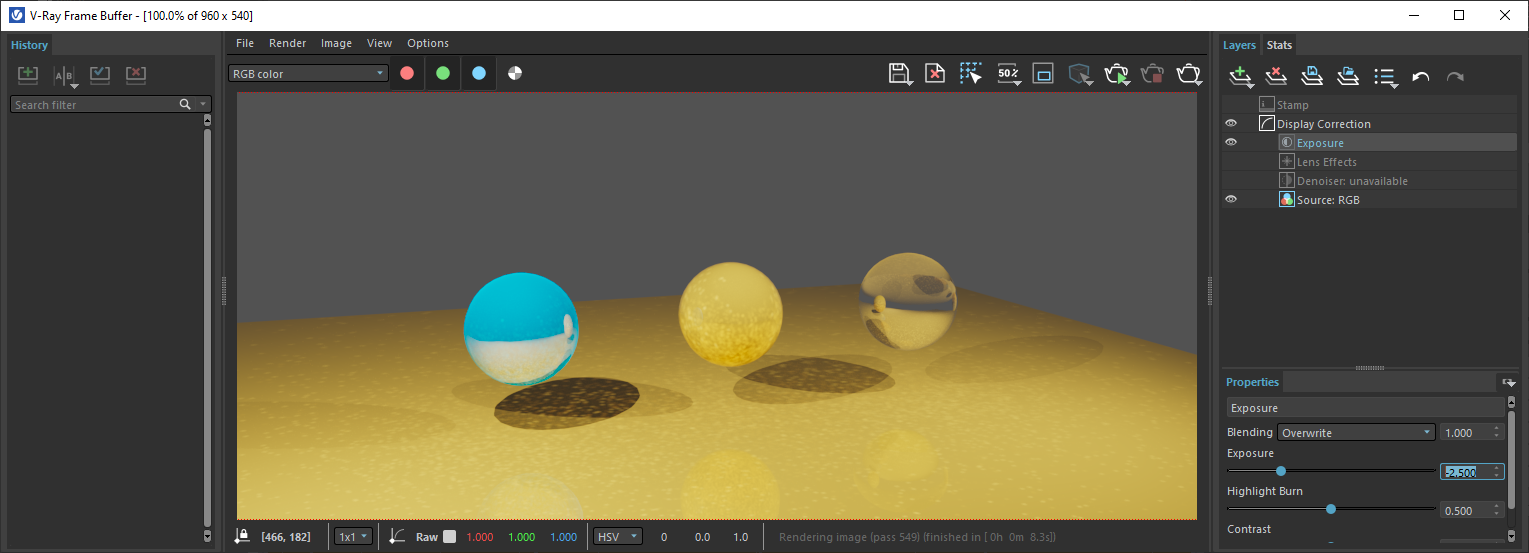
9. Select the "Render" icon in the upper left hand corner of the "Render View " window, and note that the "Render View " window is replaced by the V-Ray Render Buffer. In the first pass, the rendering is likely to be inappropriately over-exposed.
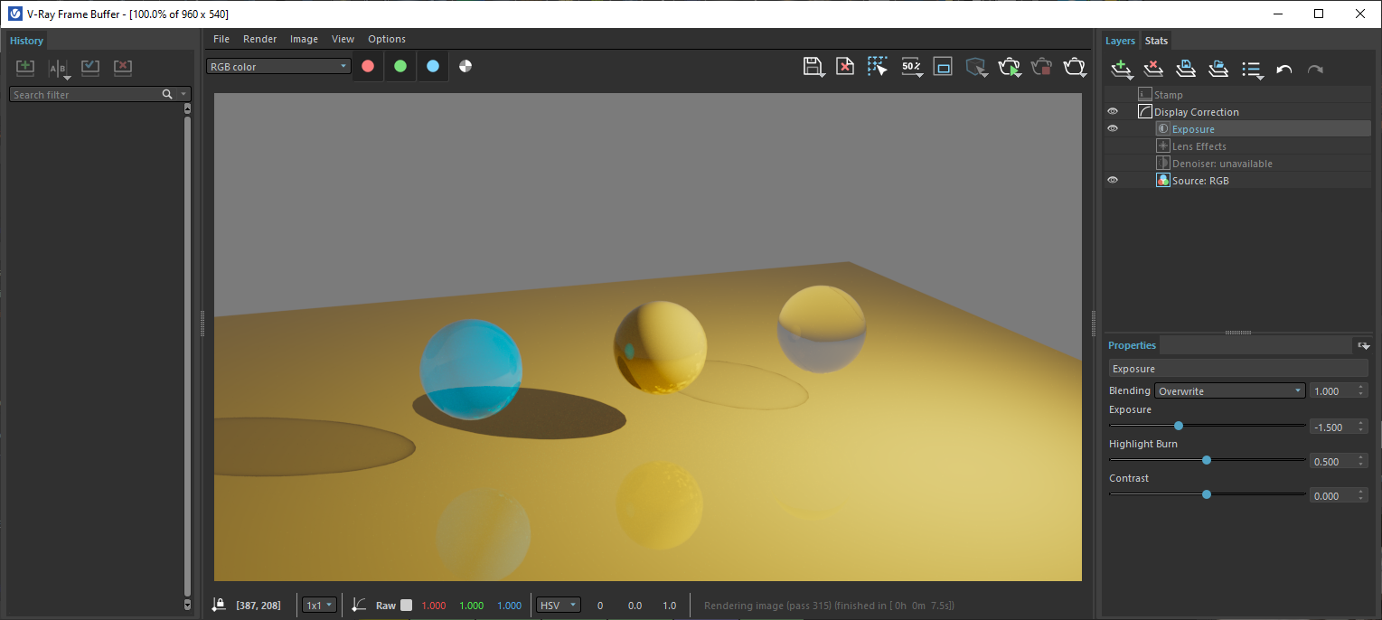
10.However, select green plus symbo and the "Exposure" option on the upper right hand menu as shown below.

11. Adjust te exposure to -2.5, the highlight burn to 0.4 and the Contrast to 0.5.

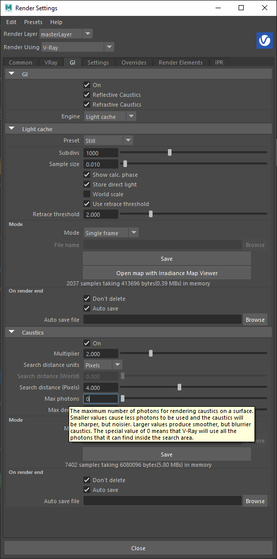
12. Next, go to the render settings for V-Ray. the "GI" tab in the first area labelled "GI" turn the upper check-box to "On" as well as the check-boxes for "Reflective "Cuastics" and for "Refractive Caustics". In addition, in the first area labelled "Caustics" turn the upper check-box to "On".
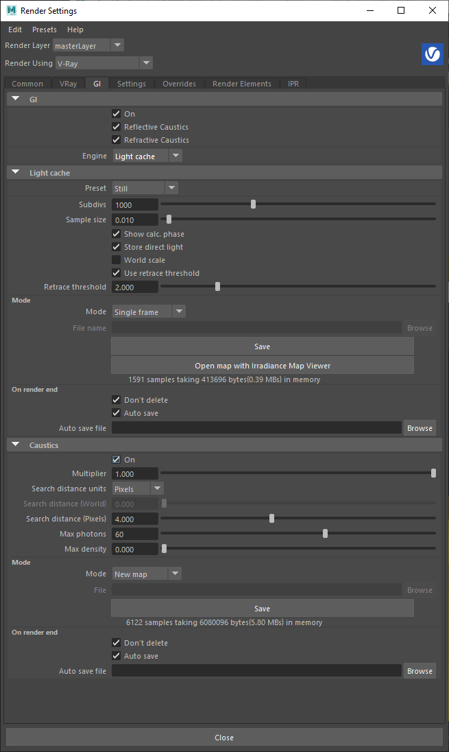
14. Re-rendering the image yields a modest change to the appearance of caustics on the underside of sphers and ground surface.
15. Change the value of the Max photos to 0. This sets the value to the be maximum range possible and increases the appearance of the caustics.

16. Add a second IES light of the same type.
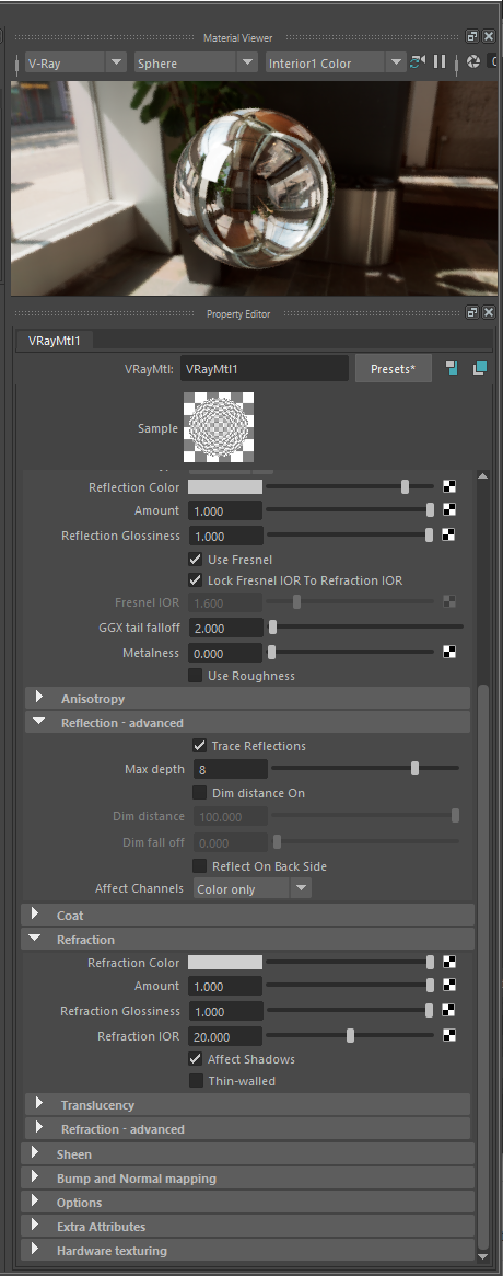
16. Increase the index of refraction (IOR) to 20 (unusully high, such as very a highly polished metal) and adjust the "reflection" and the "refraction" color sliders to all the way to the right hand side for the first and third spheres . A source of IOR values is availble at https://pixelandpoly.com/ior.html well as other web sites.
17. Re-render.
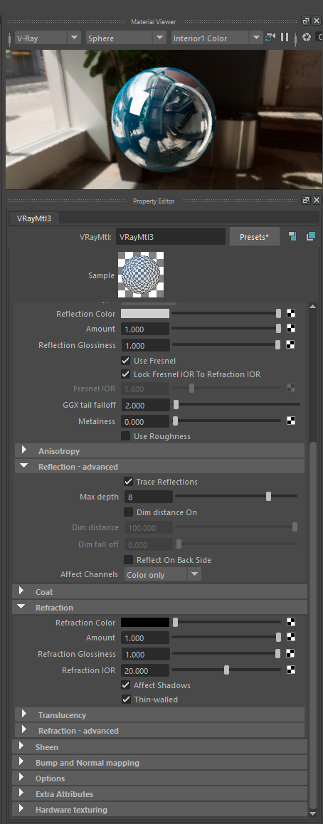
18. The sphere to the right still is somewhat unrealistic in that it appears to be more the opacity of solid metal rather than transparency glass. Howeer, ss solid glass it would bend light in a way that may also not allow full transparency, but it would bend light more and not be visible straight through. To clarify this situation we return back to the properties of the material assigned to this object. In this revision to the properties for the marerial, an IOR of1.6 to is restored for refraction. We also use an IOR of 1.6 for the material's fresnal effect (determines reflectivity at different viewing angles). In addtion the refraction slider remain full white (no opacity), and the reflection slider is also set to full white (maximum reflectivty). Here in the "Material Viewer" as in the model itsef the sphere is not self-evidently transparent . However, when the same material is applied to flat box, the transparency of the material is evident.
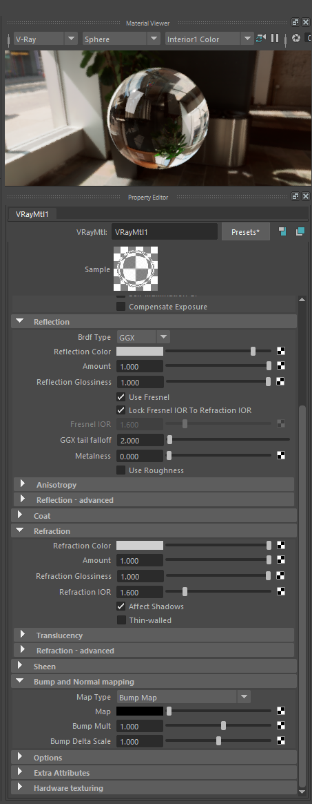
In the following rendering, a flat vertical wall-like box is added. The sphere and wall are assigned the revised first material.
![]()
Part II. Simulation of Water
1. Go to the V-Ray tab, right-mouse click on the "Sun" symbol on the right-hand side of the light types, and add a sunlight to the model space.
Once the sun is placed in the Maya model., Set the V-Ray sun position's geographical locations as:
Latitude = 38
-Mid Atlantic US
Longitude = -78
Time Zone GMT - 5:00 - US East Coast TIme
Local Hour 15 (3 pm)
Date: 11.27.2017
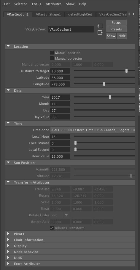
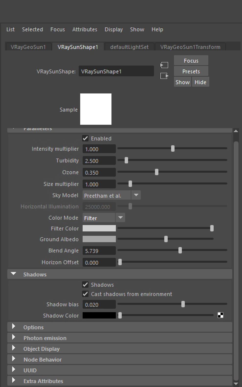
2. Under the VRaySunShape1/Parameters tab, set the sky model to Preetham et. al. and nder Ray Trace Shadow Attributes, turn on "Shadows" and "Cast Shadows From Environment".
4. Optionally, add a point source light to the model from the light palette, 3rd icon from the left, to help with middle grey scale shading values.
![]()
5. Now add a polygon surface plane to the X-Z ground plane and subdivide it into 12 x 12 subdivision units in its "width" and "height" through the channels dialog box as done in prior workshops.
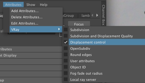
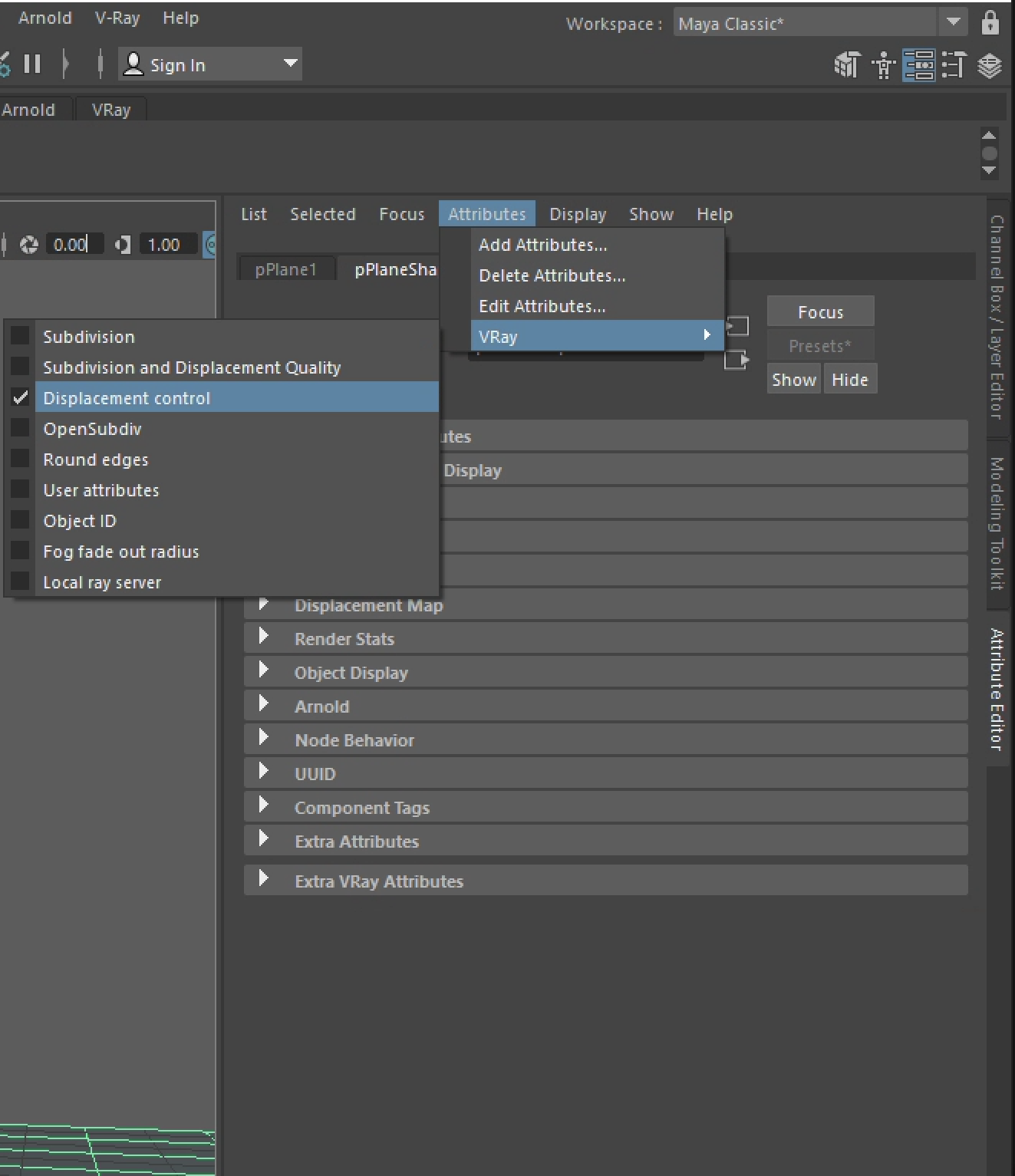
6. In the "planeShape1" tab for the polygon surface, right click on the "Attributes/VRay" menu at the top of the dialog box and add "displacement control".
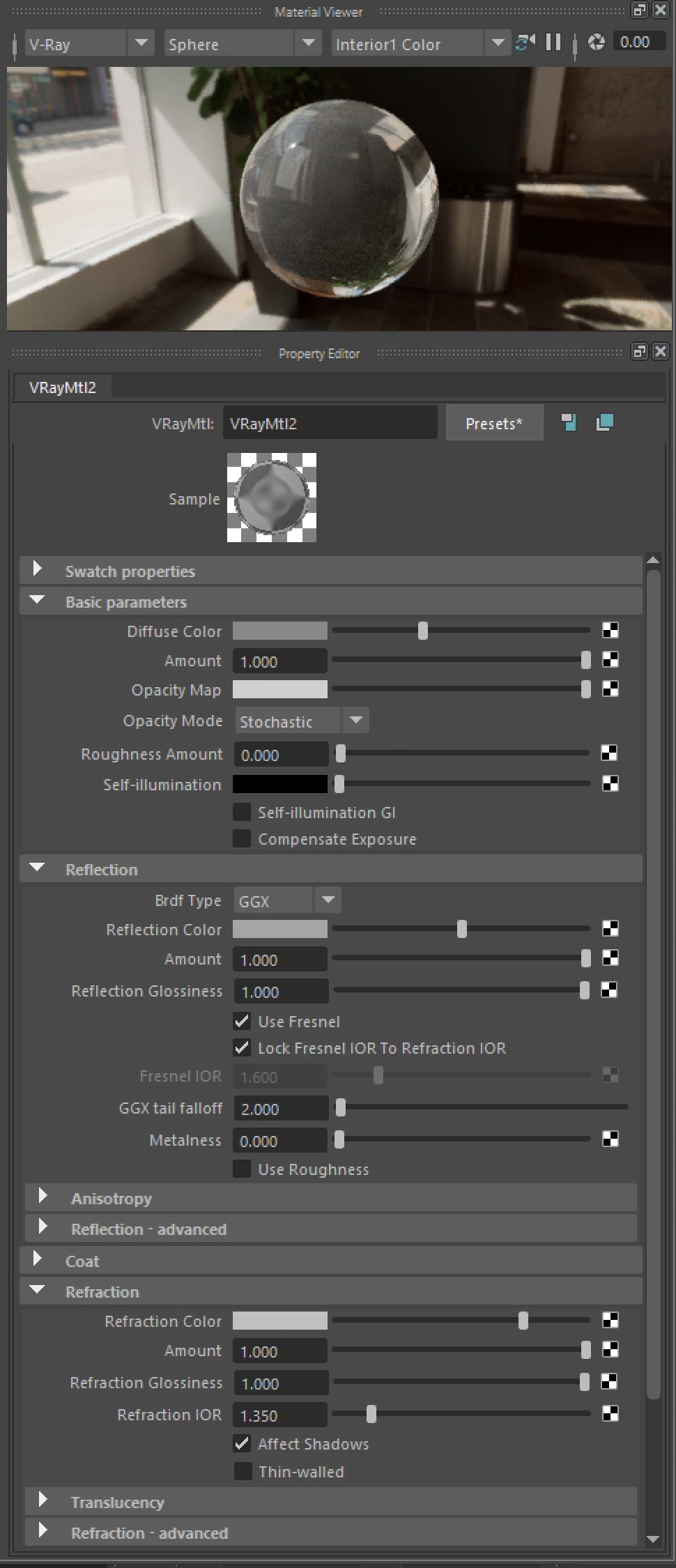
7. Within the hypershade panel create a VRay material that is a new, slightly dark gray, and also has a a mid gray reflection value and a light gray refraction value for a small degree of tansparency and refraction. Also, set the IOR (index of refraction) for water for the material to 1.35.
8. Continuing withing the hypershade window , open the bump map tab for the new material, and select the checkered box to the right pf the word "map".
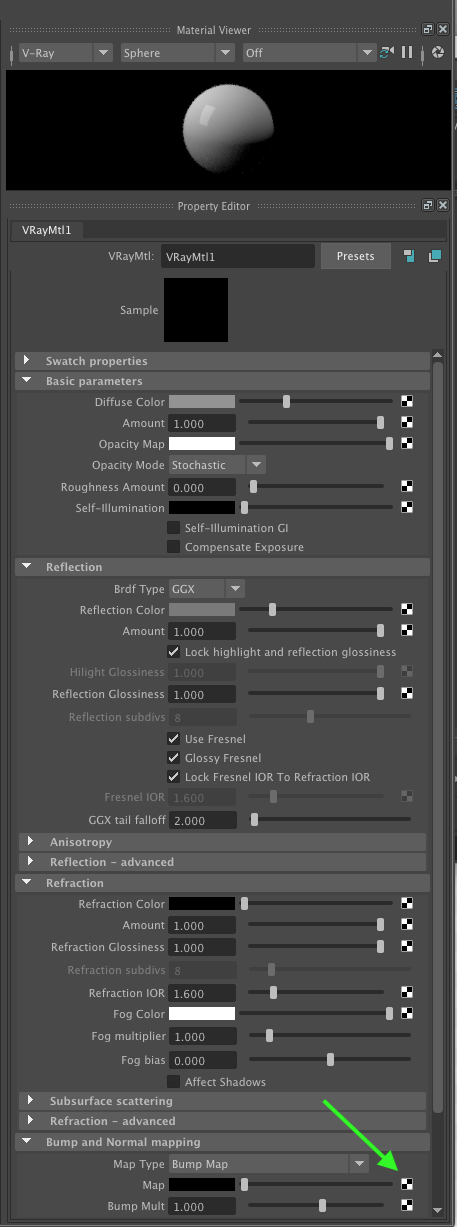
9. Now, in the dialog that follows, select under VRay 2D textures option a VRay water material.
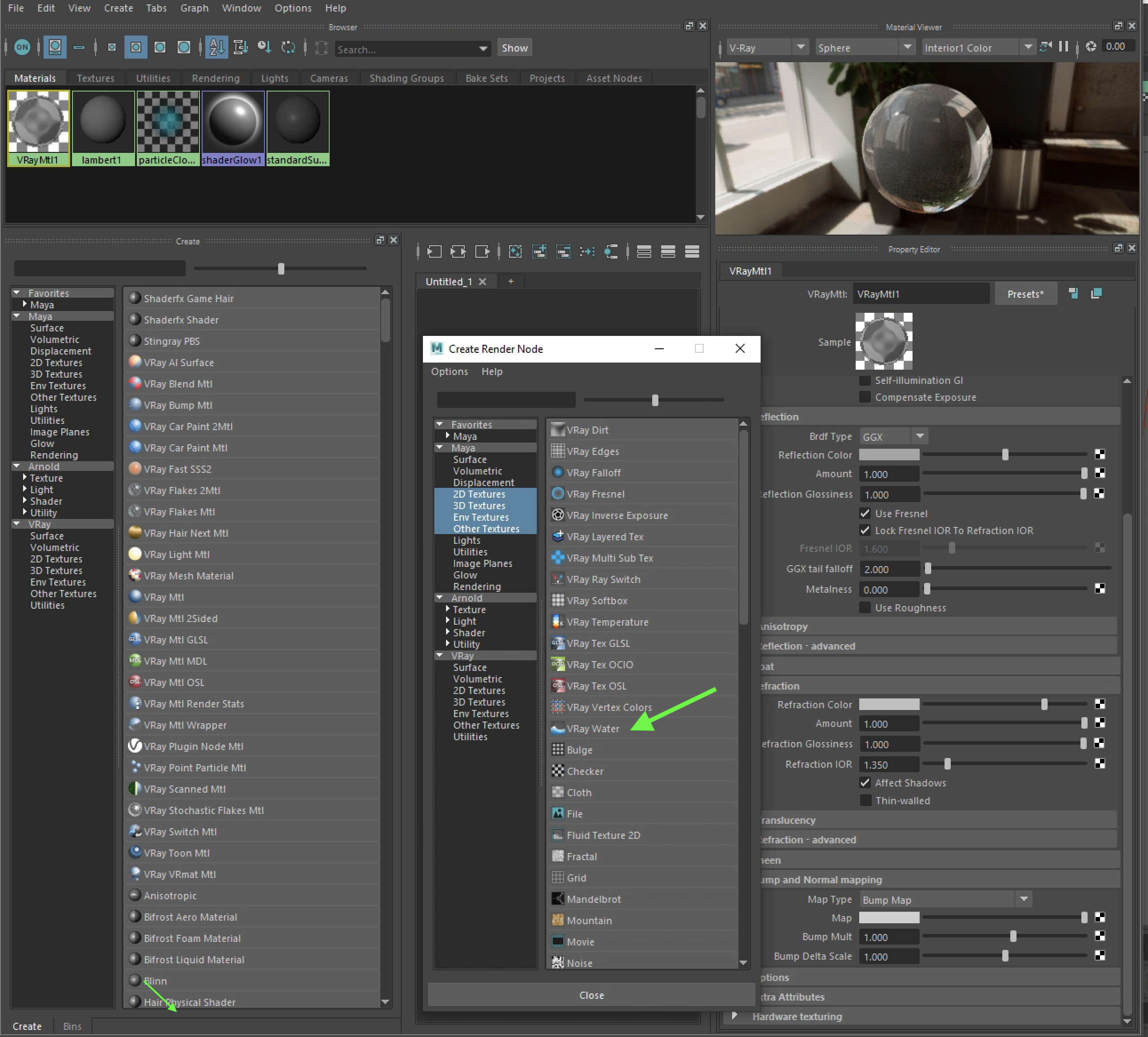
10. Applying the water properties as a bump map and adjusting its paramters, the original VRay material is modified as in the following sample.
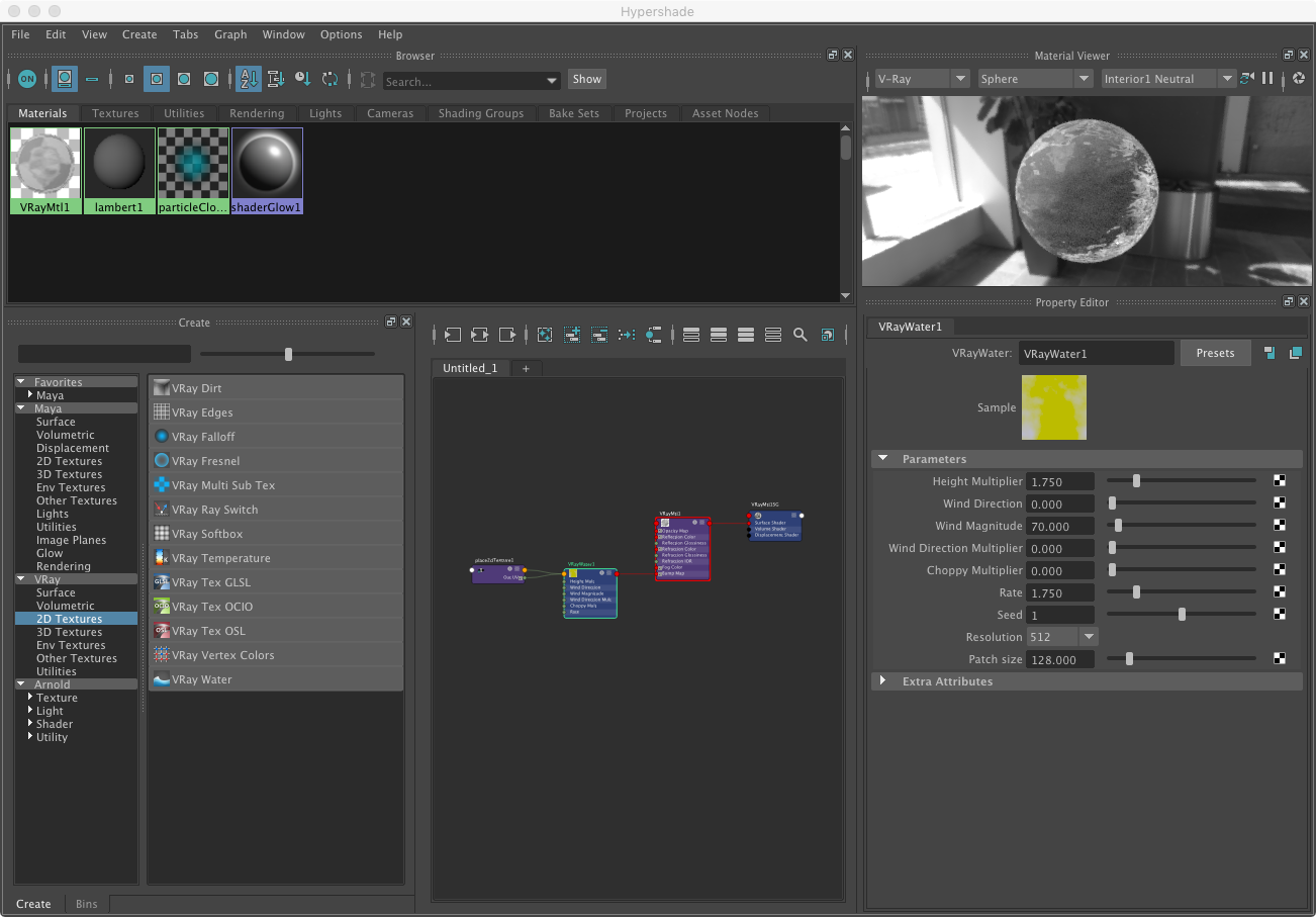
From Chaos Group's documentation, the following are the definitions for each parameter:
Height Multiplier – Specifies a scale multiplier for the whole texture.
Wind Direction – Specifies the wind direction and thus the direction of the waves.
Wind magnitude – Specifies the strength of the wind creating the waves. Higher values produce larger waves.
Wind Direction Multiplier – Specifies a multiplier for the importance of the wind direction. Smaller values will produce more variation in the direction of the waves.
Choppy Multiplier – Specifies a multiplier for the choppiness of the waves. Higher values will produce sharper looking waves.
Rate – Speeds up or slows down the movement of the waves. This value has effect only in an animation.
Seed – Specifies an integer used to set the starting point for the random generator. Different values produce different waves randomly.
Resolution – Specifies the amount of detail in the generated map.
Patch size – Specifies the real world size of one patch of the VRayWater texture outside of which the surface is perfectly periodic.
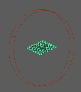
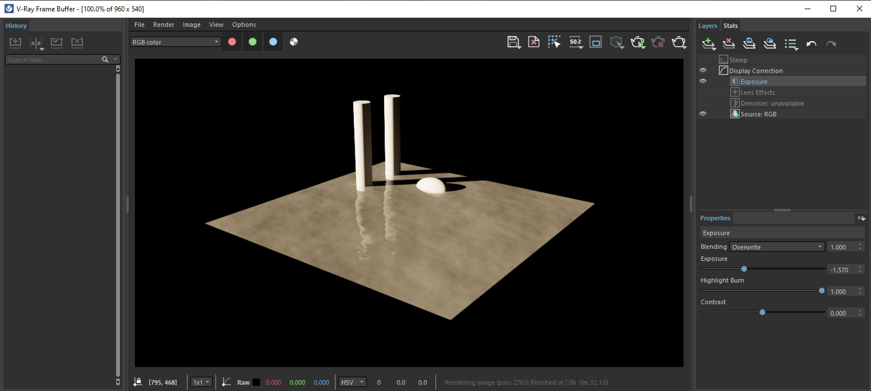
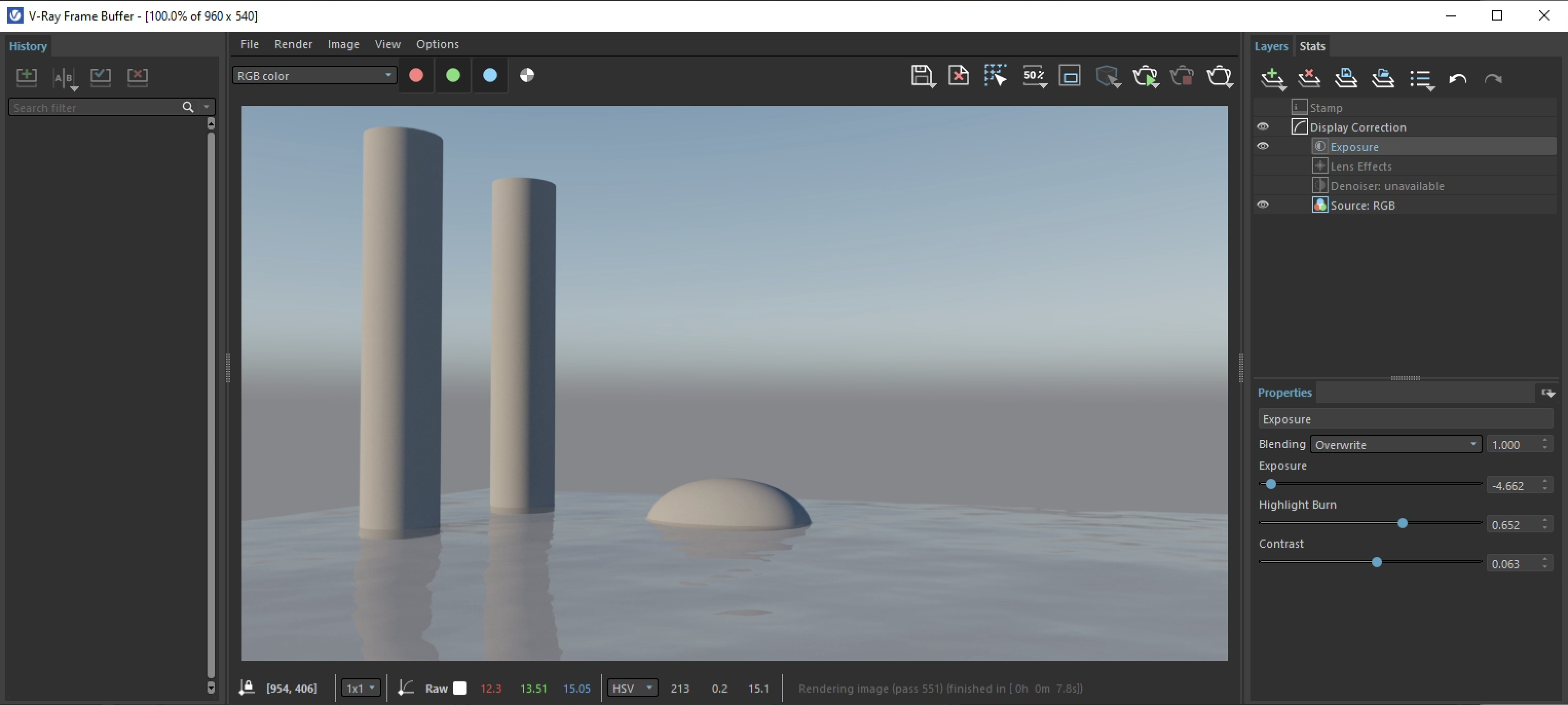
11. Add an ellipsoid and two cylinders, render in Vray and adjust the "Levels" according the procedure done in Part I of these notes. Due to sun color temperature the initial rendering of the the ground surface is a bit yellow. However, futher integrating the VRay sky and other environmental features will alleviate this. Moreover, the water material is an animated map that will cause the effects of water movement in the surface when the scene is animated.
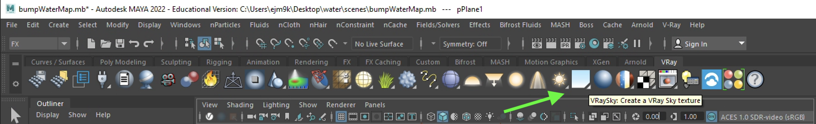
12. To add as sky to the view, go to the VRay shelf menu to and select the VRay Sky icon.
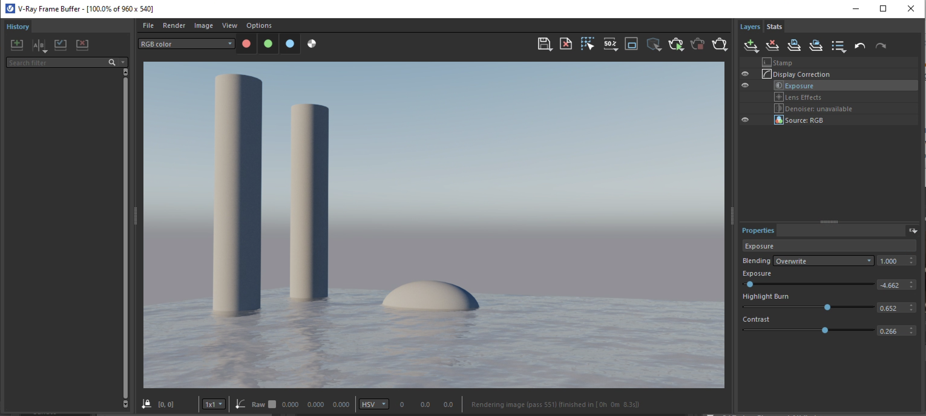
13. On the left-hand side of the Maya application window, adjust the sky setting to "Overwrite Sun Settings" and the simulation model to "Preetham et. al." This provides a convenient separate inteface for the atmospheric sky algorithm. View the model from a low angle, render in VRay and lower the exposure level to reveal a rendering similar to below. Note that the exposure level is especially low due to the brightness of the sky added to that of the the sun in the earlier rendering.
15. Returning the shader for the water, it's possible to increase the density of the wave by increasing the density of the texture map to "Repeat U V" 4 x 4 times.
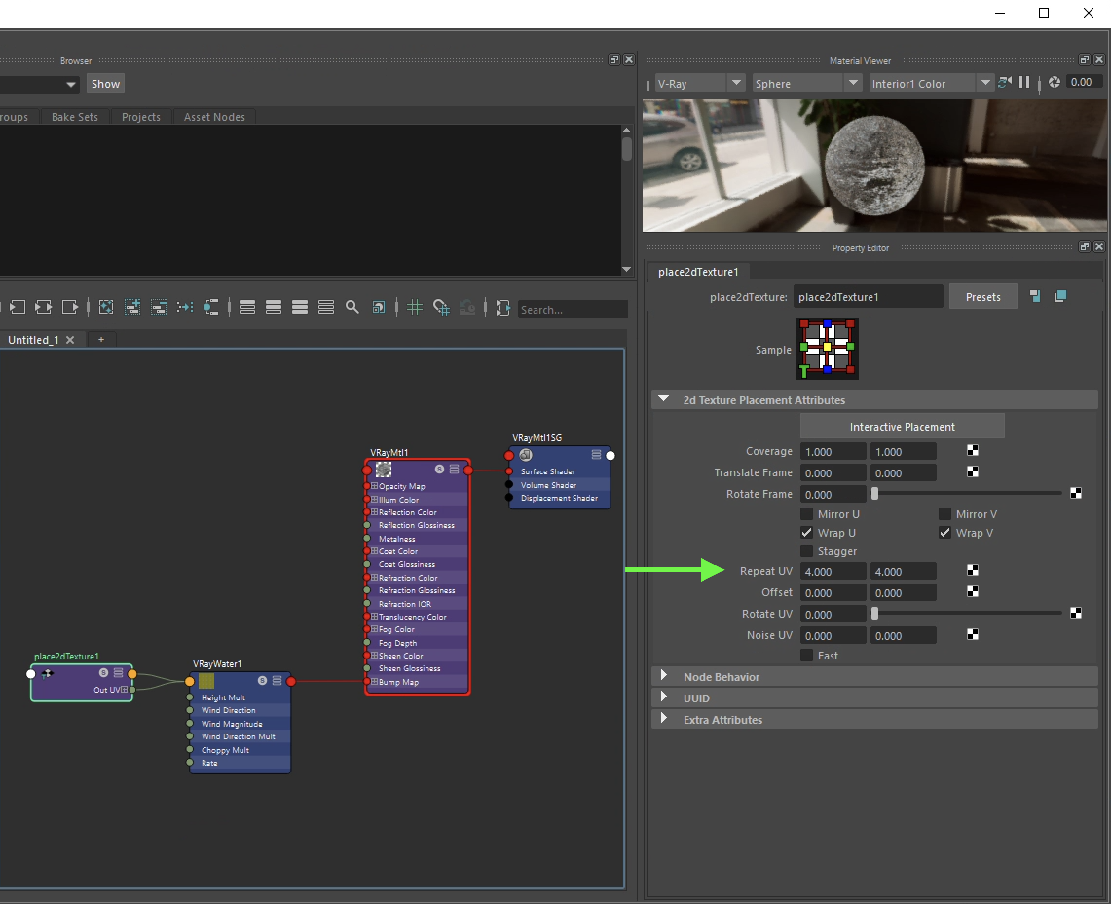
Re-render the view to see the higher density waves.
Select the following image to see a brief animated video clip.
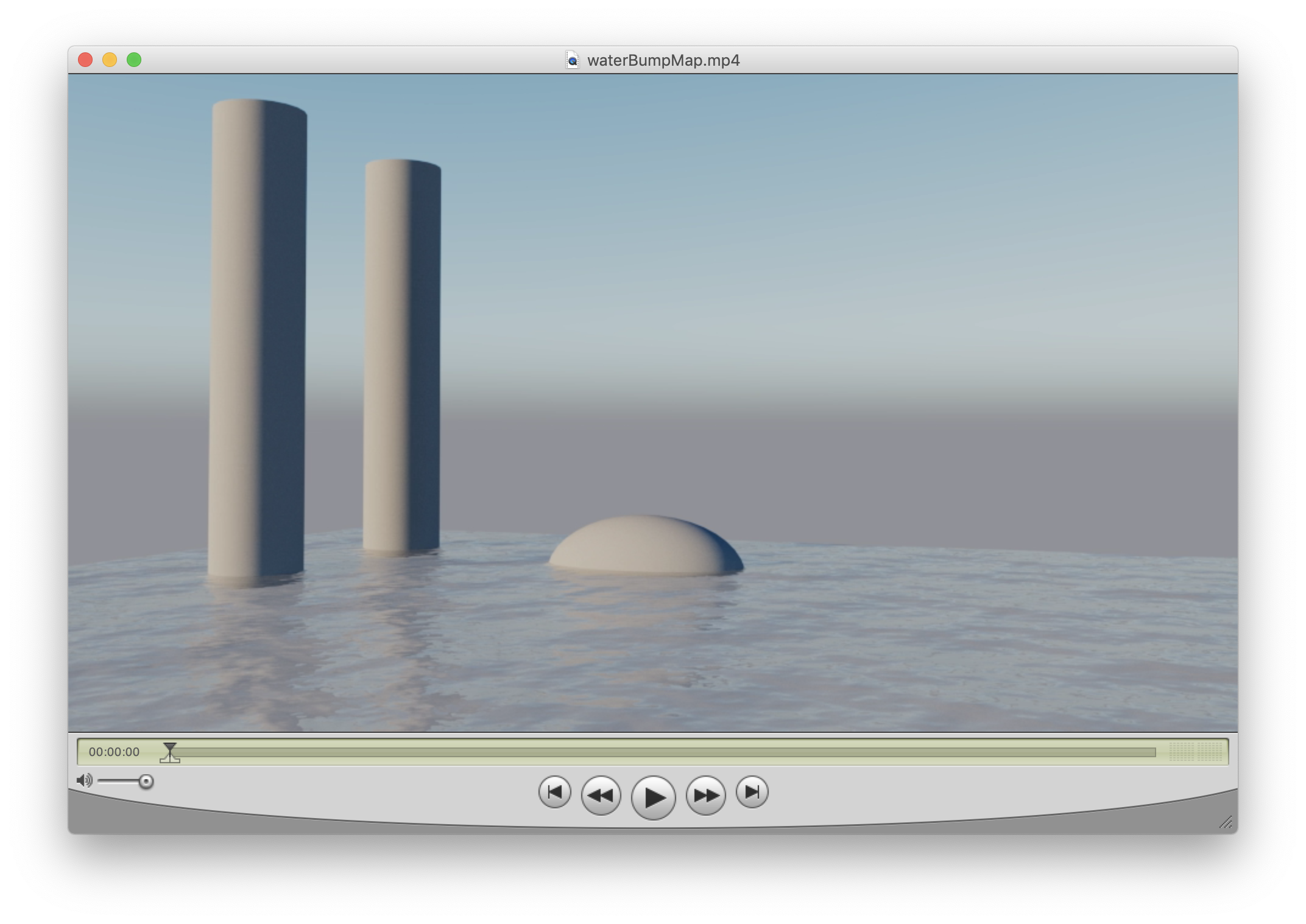
20. The renderings above use a "bump" map approach where water waves are rendered to appear to be 3D though a shading artifice but the underlying 2D geometry of the flat plane isn't changed. Alternatively, a "displacement" map creates more directly a rendered true 3D geometry that occludes other geomemtry and casts real shadows. This is possible by modifying the VRay attributes of the polygon plane such as illustrated in a tutorial posted on the web site http://www.grinning-tiger.com/.
21. Yet another method for a true 3D displacment is described here.
First, remove the "Displacement Control" from the water plane polygon, by reversing the earlier step.
Next, create a new V-Ray material with the same settings for Diffuse color, Reflection and Refration used previously, except do not create a Bump map.
Apply the new material to the water plane.

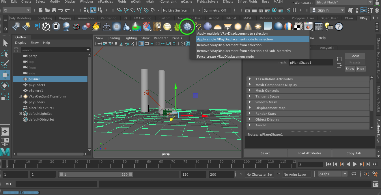
22. Next, begin by selecting the plane used to represent the water, shift-select the VRay Displacement Node from the VRay palette, right-mouse click on the the node and choose the option to "Appy single VRayDisplacment node to selection".
23. Next, within the " dialog box at the right, select the checkered icon and then the "VRay Water" animated texture utility.
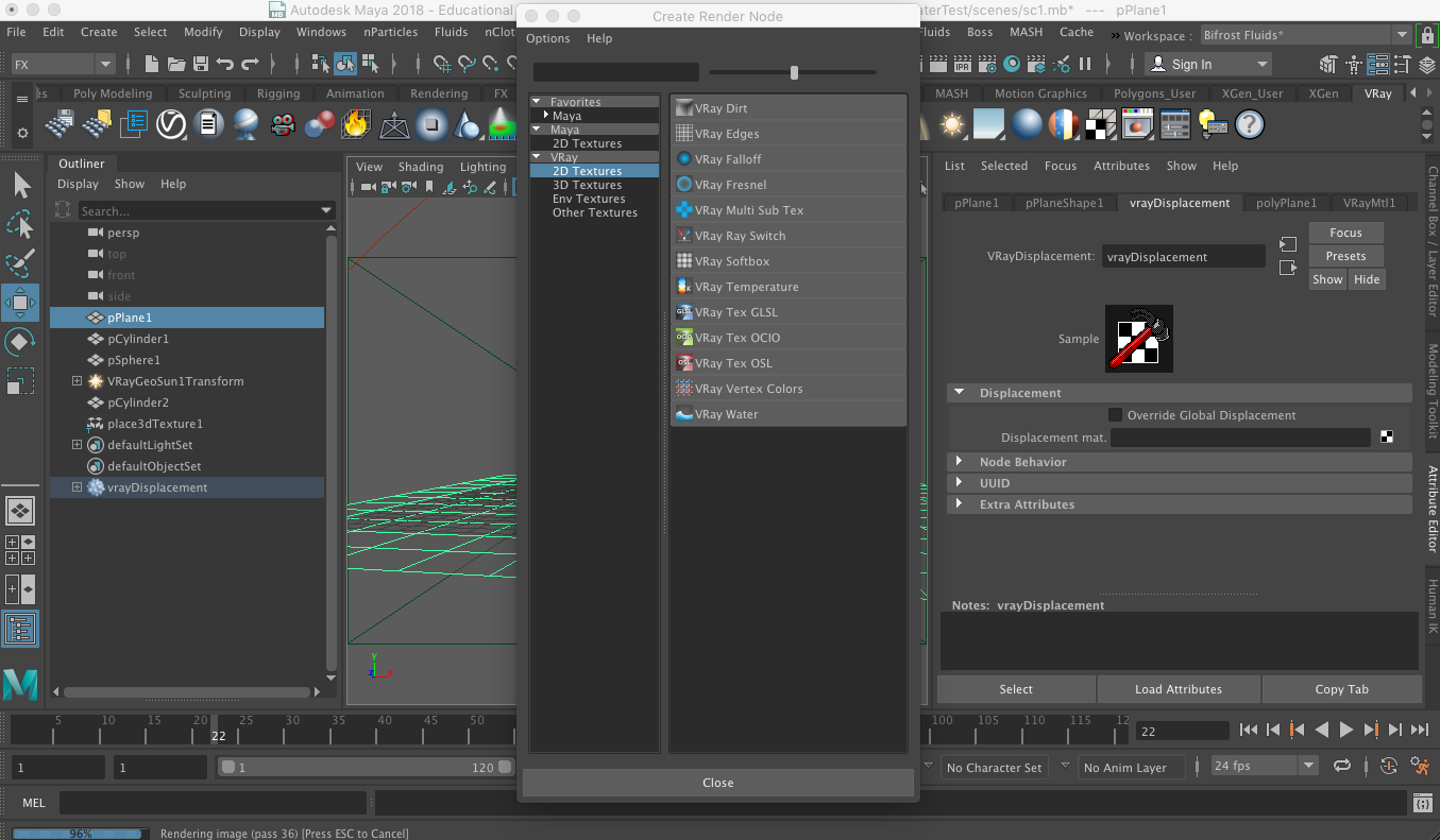
The last step in turn creates a second "VRayWater" texture. We will use this texture to replace the one that had been used for the water wave in the 2D bump map approach used previously.
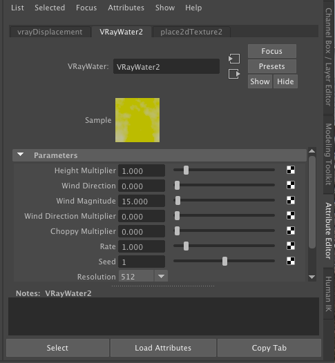
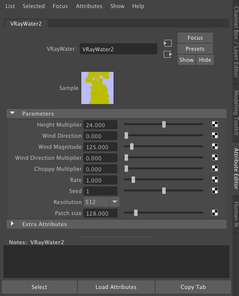
Change the parameters in the new VRayWater2 as indicated below.
24. Within the Attributes dialog box for the vrayDisplacement, turn on "Displacement control".
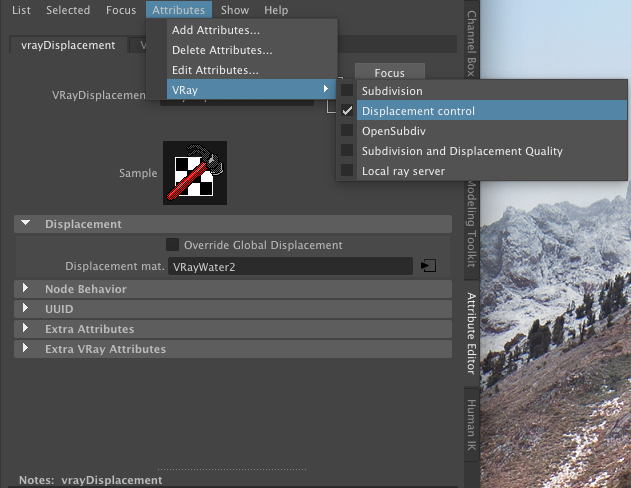
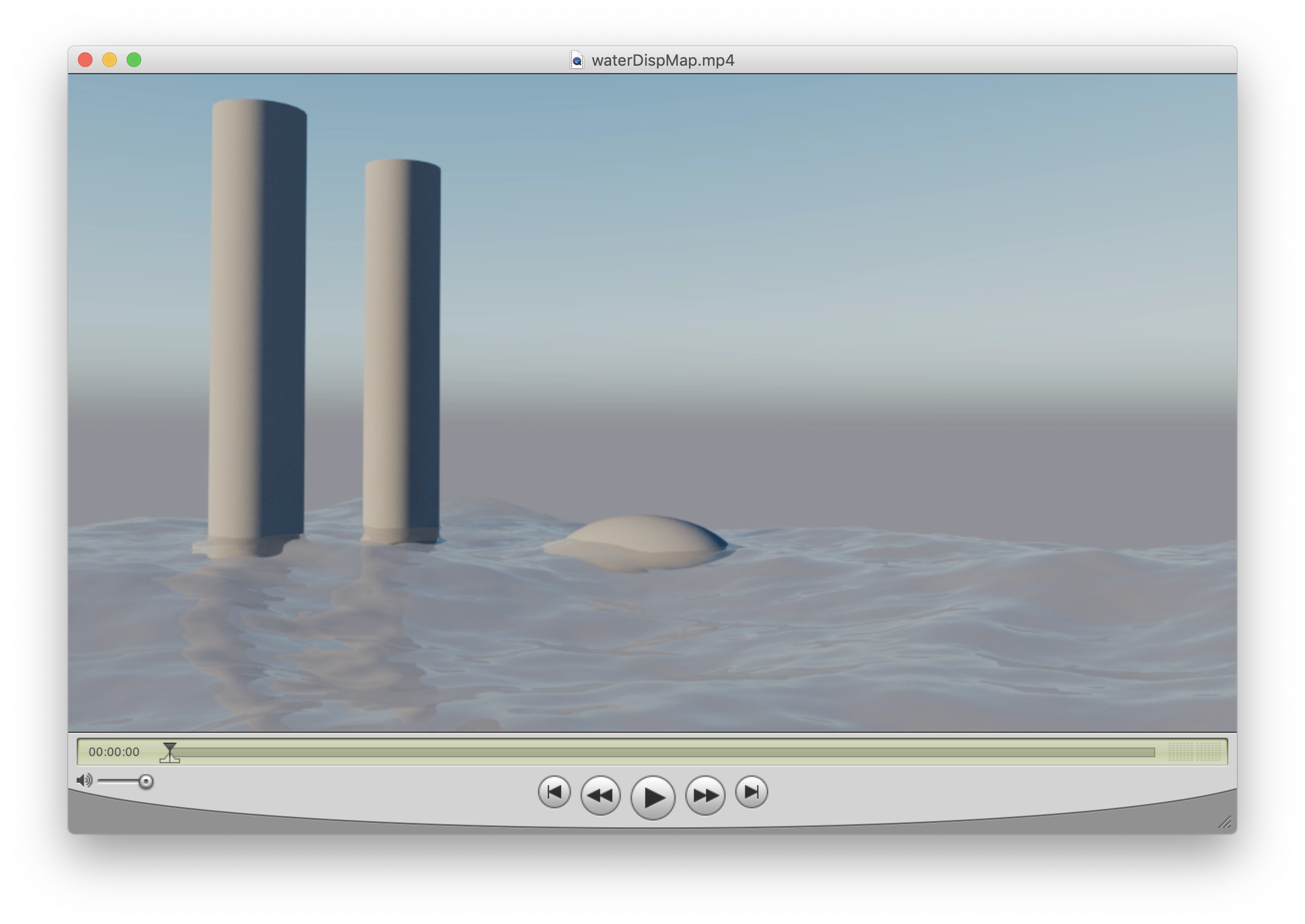
The vrayDisplacement displacement feature results in the following more complete 3D water surface that occludes part of the cylinders and the ellipsoid object.

Select the following image to see a brief animated video clip for the displacement mapped waves.