WORKSHOP/SEMINAR
PARAMETRIC RAPID PROTOTYPING: Chapter 1
| For
Internal UVa. Use Only: Draft: January 17, 2008 Copyright © 2008 by Earl Mark, University of Virginia, all rights reserved. Disclaimer |
Introduction
The direct pathway from a virtual computer model to phyiscal form making machine, and quick customization of alternatives is the intention of parametric rapid prototyping. Computer aided design from its infancy speculated on assisting architects and engineers with solving complex graphics design problems. One of the goals was to add quantitative reasoning and logical operations to the problem solving effort. Our focus in this book and its examples lies in the opportunity to exploit quantitative resoning and algorithmic procedures to the transformation from a 3D computer aided design model to physical form.
Some of the techniques that we will explore date back to the first experimental computer aided design system called Sketchpad. The Sketchpad system was developed as a Ph.D. dissertation in 1963 by Ivan Sutherland. Sutherland worked the so-called graveyard shift on building his prototype at MIT's Lincoln Laboratory. What occurred in these off hours of the night probably has surpassed in significance anything that might have been recognized at the time. The novelty of drawing graphics on a screen was groundbreaking, but not in itself the key focus of the investgation. Rather, the ability to invest the graphics with mathematical power and logic made this project an important breakthrough. Early on in the evolution of this technology, the computer based model could be used to drive physical manufacturing processes. Witin the last ten years, however, this production process has been made more affordable and accessible to the extent that its increasingly used directly in architectural practice. By harnessing the language of a computer more completely and by writing expressions that more completely capture formal design intentions, it is possible to extend the power of this technology realize more complex and adaptable architectural forms.
The Sketchpad system and others that followed established techniques of working with Euclidean geometry that could not be done as easily by hand on paper. This included automated representations of most primitive geometry, such as lines, circles, arcs and eventually splines. The Sketchpad system included "intelligent" ways of associating together graphic figures into objects. These "intelligent" objects included parent objects, and instances of their children and grand-children.Such concepts, as we will review in later chapters of this text, laid out a new foundation for how to organize geometry with respect to working on a design problem..
CAD systems today have advanced beyond Sketchpad the logical foundations for automating the generation of 3D geometry. Yet, probably no system can pre-determine all the specific processes that an architect might apply in geometrical modeling. That is, architects and other designers may be faced with unique design problems that call upon customized approaches to the use of math and logic in the description of three-dimensional form. For example, a curved wall by the architect Frank Gehry as used in the Seattle Music Museum project called upon an architect to write a computer procedure that would customize the geometry needed to accommodate the physical materials used in the exterior skin. The computer program generated a precise geometry that adopts to varying conditions determined Gehry's doubly-curved forms. The computer procedures also provides a description that could generate variations on a physical test model made from modular components. The system was ultimately used to specify the cutting of the actual materials used in the finished built work.
Unless this level of control over the geometrical modeling process is accessed, the typical computer aided design system today still seems to mask the basic underlying logic of its software. For the typical user, it is if their CAD system is a magical black box, where different command inputs will provide different somewhat pre-determined types of three-dimensional models. There are a great many geometrical models that can be accommodated according to these pre-defined methods of using the computer, but a greater freedom is possible by adapting the logical of the computer procedures more completely.
In a similar way in an earlier time, Serlio believed that the readers of his Book of Architecture needed to have some foundation in geometry to give a good account of their efforts in designing buildings. He wrote down step by step procedures for drawing curves used in the architecture of his day, such as in the construction of an oval or the derivation of an occulus. Similarly, we are concerned here with more complete control over geometrical modeling in a CAD system as individual designers. We will begin in Chapter 2 with the geometry of Serlio. In later chapters, we will look at the description of geometry that advances beyond what was applied to architecture in Serlio's time. We test the proposition that a computational process, if more freely and expertly controlled by a designer, can adopt more completely to our intentions. It can be used to discover the particular invisible mathematical order and quantitative basis that may be applied to each instance of architectural design.
The book is organized into three parts: (1) geometrical descriptions of architectural form, (2) how these descriptions may be harnessed within a computer programming language, and (3) the adaption of procedures to parametric rapid prototyping. In a larger context, it looks at the potential of the computer to explore expanded models of geometry used by designers.
Programming
To take advantage of computer power, we need an appropriate vehicle for representing abstract things and processes in the world. In architecture, we might want to generate advanced dome geometry, simulate how a tensile fabric retracts and unfurls, or take into account other assemblies of objects or processes. In a formal sense, these things may be represented on the computer as either processes or data. To date, a number of different computer programming envrionments provide for this ability.We will also be able to take our knowledge of a form generation process and test it by writing a computer program. In our introduction to a procedurally based programming language, we will first recreate classical architectural geometry as may be found in the illustrations of Serlio and Palladio. Laer one, we will examine procedures that may be used to describe diverse cellular and crystalline forms in nature as explored by D'Arcy Thompson in his now well publicized treatise On Growth and Form. As we examine more advanced programming techniques, we will take on repetitive forms such as soap bubbles and beehives, and fractal forms that include mountains, trees, and snowflakes. Finally, we will also apply programming techniques to the animation of architectural elements.
|
Koch Curve Fractal Animation
Software for Writing Macros
Generative Components is a new software program with a scripting
language. Expressions within this scriping language are based loosely
on C# syntax. This will be the basis for most of the exercises in our
class and may be obained free of cost by meeting with Eric Field, room
134 Campbell Hall. Visual Basic for Applications (VBA) programming
language provides another simple means to also write procedures, and is
avalable as a Macro programming language within both Microstation and
Rhino. Similarly, MEL is a scripting language which can be used to test
these techniques in MAYA. By following a step-by-step introduction to
the use of Generative Components, students more familiar with the
object oriented VBA programming language can transfer their
understanding to it.
|
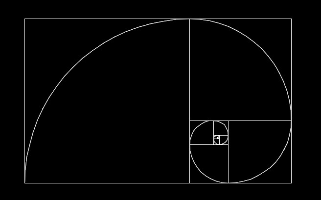
Using Sample Programs This text has been developed as an HTML - World Wide Web document. It is available in hard-copy and also may be read by means of a World Wide Web browser. Microstation's implementation of Generative Components is the language used throughout the text. The programs are organized into projects, and projects are composed of modules. For example the code of such a module(a "gct" generative components file) that draws a series of golden rectangles is linked here:
This code incorporates expressions that will be explaned in later chapters of this text.The use of generative components files is incorporated throughout the text. Microstation's software provides help documentation on how gct files are created. Once the code is executed, a series of golden rectangles would be created within the active CAD drawing. You may need to invoke the Microstation command "Fit View" in order to view the entire series of golden rectangles, or in some other way move about the view window in order to find them. The drawing within the CAD system view window should appear as follows:
|
Representing Data in Variables
A variable is a place where your mommy likes to place things. She can put a "pi" in there, or a "square root", etc.. roughly paraphrased from a popular lecture course by Dr. Roger Kaufman, MIT, late 1970s.
GCScript
The GCScript programming language provides a simple way to describe processes and data. Even complex programs can be broken down into simple statements.
We begin our study of the GCScript language with the means of representing data. In GCScript, we can store data in a variable. In high school, you probably learned to think of a variable as a place where you can substitute a number in an algebraic expression:
| m = 2 * n; |
You will recall that if you substitute the integer value of 3 for the variable n, then it would result in the assignment of a value of 6 for the variable m in the equation above. Variable names in GCScript can be made to store many things of interest. They provide the starting point for describing any number of objects.
A simple GCScript statement for the assignment of a value to variable is:
| n = 3; |
The statement translates to “assign the value of the integer 3 to the variable n”, and is referred to as an assignment statement. The “=“ symbol is referred to as the assignment operator. The value of the right hand side of the “=“ symbol is assigned to the variable on the left hand side. We might also say that right hand side of this statement is stored in the variable specified on the left hand side.
A more complex assignment statement may include variables on both the left and right hand side as we have already considered in our example of high school algebra:
| m = 2 * n; |
In the statement above, we can say as before that we are assigning something to the variable “m” on the left hand side of the statement. The statement on the right hand side is equivalent to saying “the contents of the variable n multiplied by two”. As a result of this statement and the statement above it (e.g., n = 3), the numerical value 6 is stored in the variable m.
Note that both n and m are temporary places where you can store things. In VBA, we might remake the statements above so as to change the contents of n and m:
| n = 4;
m = 2 * n; |
The last two statements above reassign new values to the variables “m” and “n”. The old values of “m” and “n” are simply thrown away. Note too that we have sneakily introduced another element of the programming language. The operator * refers to multiplication as in an ordinary algebraic expression. We multiply two by “n” on the right hand side of the statement. We will examine more operators at the end of chapter 2.
Variable Types
In GCScript, variables should be declared as one of three primary types: integer, real or string before being put to use. An integer variable can be used to store a whole number, such as 1, 2, 3, -1, 0, 22, etc. A real variable can be used to store a real (floating point) number, such as 1.0, 2.2, 4.0, -1.03, 22.22, etc.. A string variable can be use to store text, such as the character string “house”, “wall” or "red roof".
Within a GCScrip, we would typically declare the variable type before using it within another kind of statement. For example, we can declare the variable m as an integer type variable with the dimension dim statement:
| int m; |
The variable m might then be subsequently used in the program within the assignment statement:
| m = 2; |
Or, we might declare the variable x as a real (floating point) number with the statement below, where double refers to a particular type of real number that can store a large number of significant digits:
| double x; |
The variable x might then be subsequently used within the assignment statement (note that by convention commas are not used to separate the zeros as they would be more typically expressed in a hand-written statement):
| x = 2000000.0; |
As a third example of a variable declaration in a GC script, we can declare the variable mytext as a character string as follows:
| string mytext; |
The variable mytext might then be subsequently used within the assignment statement:
| mytext = "hello world"; |
Variable Declarations
A declare statement has several purposes:
Different programming languages provide different rules with respect to how variables are declared and the range of possible types. This would appear at first glance to be a nuisance. In many respects, however, it is a way of reinforcing clarity. The rules force you to be explicit with respect to whether a variable is meant to represent an integer, a real or a string value. The explicit declaration in turn also makes the program easier for you to read and easier for you to track its logic. It also makes the program easier for someone else to read if they are responsible for reviewing your work. That is, you establish the kind of information to be stored in a variable through the dec;are statement. Every time you see the variable used you have a sense of what its intended purpose is by virtue of its possibly mnemonic name and the way in which it had been declared. The declare statement then becomes a point of reference at the beginning of a program for clarifying to the reader what particular variables do.
As we will also see shortly, the rules ensure that you size a variable's storage requirement only as large as necessary. This means that your program is more efficient in its use of the computer's memory than it would be otherwise. In the case where many variables are used, the cumulate effects of this efficiency can be significant.
Variable declarations can be distinguished by type and also by variations within a type. For example, integers may be declared as being of integer or long dimension. Integer variables of integer dimension may range in value for whole numbers from -2,147,483,648 to 2,147,483,647. Long integers can hold values of whole numbers within a larger range from -9,223,372,036,854,808 to -9,223,372,036,854,807. The declaration statement for a number declared as an integer allocates less memory than the dimension statement for a number declared as a long. There is a cost-benefit aspect to this that trades off the allocation of memory needed for a variable against the potential range of values it may need to hold. That is, its better to use less memory for the variable if the range of values is in the range of-2,147,483,648 to 2,147,483,647, and to use greater memory only if a greater range of values is needed.
The syntax of the dimension statement within a GC script program for integers is as follows:
| integer numdoors;
long numbricks; |
Variable declarations for real (floating point) numbers may hold a decimal number of up to seven significant digits with negative values in the range of -10 to the 308th power, and positive values in the range of 10 to the 308th power. The double precision floating point variables are declared as follows:
|
double bldgsize; |
Variable declarations for strings make take one of two basic forms. You may use the as string clause as cited earlier, Some programming languages and implementations of BASIC may limit string length to 80 characters. "Old timers" in the field of computers (say anyone over 40?) may tell you that this is because old punch cards used to have up to 80 slots. This is still considered to be a reasonable size limit for strings.
| string roomname; |
Note that the symbols %, &, !, # and $ are available in VBA 6.0 for compatibility with older versions of the BASIC programming language. However, more explicit declarations using the words integer, long, single, double and string are preferred. These basic kinds of variable declarations are summarized in the following table:
| Variable Type | Length | Declaration Clause | Examples |
| Integer | Small | int | int numdoors; |
| Integer | Large | long | long numbricks; |
| Floating point | - | double | double roomsize; |
| String | - | string | string roomname; |
Lists
Within the GCScript, we can create our own more complex data types with use of curly brackets, (e.g. the list {1, 2, 3}). Furhermore, we can nest curly brackets to create to create a more compound expression for storing data than we have seen before. The general intuitive organization of such a list is:
|
In other words, a list consists of n fields. Each of these fields is either another list or a direct value. We might say that each field can store a specific piece of information in the form of an integer, real, or string variable. Lists are convenient for accommodating collectdions of information that may be put to a variety of purpose in a cad system.
For example, a list for a French window might contain sublists or values to store its name, width, height, and additional design specifications.

Pella Windows Clad In-Swing French Door
The initial list consists of the window specifications
that might vary among different French windows. This might include a window name (expressed as a text string), width (in feet expressed
as a floating point number), height (in feet expressed
as a floating point number), glazing (expressed as
a text string), design pressure (in pounds per square foot expressed
as an integer), air infiltration (in cubic feet per minute expressed
as a floating point number), and exterior finish color (expressed as a string).
|
For example within GCScript, this list would be created with the following expressions:
|
string name; myFrench-door = {name, width, height, glazing, pressure, infiltration, color}; |
In the last line of the above example, we have created a list "myFrench-door" list from which individual variables in that list refer to specific values.
Once the window French-door has been created, the individual fields within the list type might be assigned using the zero based index system as in the following example:
| myFrench-door[0] yields the value "in-swing" myFrench-door[1] yields the value 5.0 myFrench-door[2] yields the value 6.8 myFrench-door[3] yields the value "smartsash2" myFrench-door[4] yields the value 40 myFrench-door[5] yields the value 0.34 myFrench-door[6] yields the value "white" |
Suppose that we want to modify the values of some of the fields for myFrench-door. For example, we might want to change the value of its width to be equal to that of its height. Here too we can use variables in the re-definition of this list;
|
width = height; myFrench-door = {name, width, height, glazing, pressure, infiltration, color}; |
Or, we can modify the list using the index 1 for width;
|
width = height; myFrench-door[1] = width; |
Similarly, suppose that we want the width field to be equal to the height field times 1.5. Using the multiplication operator that we have seen before at the beginning of this chapter, we might write the assignment expression:
|
.width = .height * 1.5; myFrench-door = [1] = width; |
We now want to understand how variables may be incorporated within a GCScript. This will be introduced in the chapter that follows. In the meantime, a basic grounding in how to use a CAD system would be helpful before using it as an engine to run the GCScript.
Getting Started with Computer Aided Design
The documentation produced for a CAD system by its developer typically includes a series of tutorials which provide a quick overview of its fundamentals. Microstation's Geneative Components, the system referred to in this text, has developed tutorials on line in the form of a hypertext document. You might now want to glance over the beginning of this document if not more thoroughly examine it. If you are already working in Generative Compnents, it can be reviewed by selecting the menu item Help. The icon should be loaded in the upper right hand corner of the GC Transaction File window under the Help/Contents page. A basic understanding of the software needed to proceed should include
|
Fundamentals |
|
Once you have established a base level introduction to the program, you might then also try creating a feature such by placeing two points to determine a line and then placing a line;
| To place a line: |
|
Within the next chapter, we begin to examine how variables may be used with the context of a simple computer graphics program to draw a line. Our discussion also begins to focus more closely on the spacific kinds of variables typically used in geometrical modeling.
Homework1: Draw a simple graphics figure by creating a series of features.