
WORKSHOP/SEMINAR
PARAMETRIC RAPID PROTOTYPING: Chapter 7
| For
Internal UVa. Use Only: Draft: March 7, 2008 Copyright © 2008 by Earl Mark, University of Virginia, all rights reserved. Disclaimer |
Solid Modeling and Boolean Operators
This chapter lays out the basic concepts for three dimensional solid modeling. We examine the Boolean operations which can be used to combine solid models in different ways. The specific invocation of Boolean commands is done using Generative Components functions, but the methods used are generally applicable to the Boolean commands in most other CAD systems. The end of the chapter develops functions for describing architectural forms that may result from solid modeling.
Primitives
The assembly of an architectural model may begin with the construction of solid elements that would appear to have both mass and volume. The most basic building blocks are solid modeling primitives. The primary primitives include a rectangular box, a sphere, a cylinder, a cone or truncated cone, and a torus as depicted in the illustration below.
Solid Primitives: rectangular solid, sphere, cylinder, truncated cone, torus.
As William Mitchell has observed, these solids correspond to the primitives noted by Corbusier in his Five Points of Architecture, a core geoemtry for architectural form making. Given a set of solids, it is possible to combine and re-combine them in combinations that can yield a great variety of architectural shapes. The most simple combination of these would be the equivalent to simple stacking, as in the assemblage of toy blocks below from primitive solid shapes.

Additive Assembly: rectangular solid blocks copied and stacked.
Boolean Operations
More complex solid models can be obtained by applying Boolean operations to the primitive solids. In the following image we see the results of applying three different kinds of Boolean operations.
The UNION operation on two or more solids is similar to an "OR" logical operator. That is, we get the resultant shape R from any number of initial shapes S1, S2, S3, .... SN such that any part of S1 "OR" S2 "OR" S3 "OR" .... SN is also a part of R.
The INTERSECTION operation on two or more solids is similar to an "AND" logical operator. That is, we get the resultant shape R from any number of initial shapes S1, S2, S3, .... SN such that any part common toS1 "AND" S2 "AND" S3 "AND" ....SN is also a part of R.
The SUBTRACTION operation on two solids is more complex. It performs the equivalent of combining the "AND" and the "NOT" logical operators. That is, from two initial shapesS1and S2, S2 is subtracted from S1 such any part of S1 "AND NOT "and not a part ofS2 is also a part of R.
The illustration below provides examples of all three operations on three sets of paired shapes (a variation on this diagram was initially developed by AutoDESK Inc for its solid modeling software). The top row consists of the initial three pairs of spheres. The first pair is overlapping, the second pair is coincident (overlappling 100%), and the third pair does not overlap at all. The second row shows the result of applying the UNION operation to each of the pairs in the first row. The third row shows the result of applying the INTERSECT operation to each of the pairs in the first row. Finally, the fourth row shows the result of applying the SUBTRACT operation to each of the pairs of the first row, where the second sphere of each pair is subtracted from the first sphere.

Boolean Operations on Three Pairs of Spheres
Some Three Dimensional Examples
Groin Vault
The following sequence of solid modeling operations will produce a groin vault. The images are rendered in wireframe and fully rendered (raytraced) pairs so as to make the sequence of operations more apparent.
| Operation | Wireframe Rendering | Raytrace Rendering |
| Insert Solid Cylinder |  |
 |
| Insert Second Solid Cylinder of Smaller Radius |  |
 |
| Subtract Smaller Cylinder from Larger Cylinder |  |
 |
| Copy and Rotate Hollow Cylinder and Union The Cylinders Together |  |
 |
| Insert Rectangular Solid |  |
 |
| Overlap Rectangular Solid With Union of Solid Cylinders |  |
 |
| Intersect Rectangular Solid with Union of Solid Cylinders |  |
 |
|
Close-up View of Resulting Groin Vault |
 |
 |
The resultant groin vault is reproduced below in the Virtual Reality Markup Language, such that you can examine it in 3D. Switch on the head lamps so as to view the underside of the vault
Groin Vault VRML On Separate Page
Pendentive
A similar series of operations results in the construction of a pendentive as outlined below. This sequence, first suggested by Mitchell, is reproduced here in the form an animation. The Boolean operations are the basis for each successive frame.

Pendentive VRML On Separate Page
Developing Solid Geometry Within A Simple Procedure
We now examine the possibilities of solid modeling with the assistance of a scripting language. Scripted functions can help to enhance the solid modeling process with computational power and mathematical order. A function to draw a solid sphere is not substantively different than the simple graphics functions we first examined in chapter 2. We introduce here a function slab_cyl.gct to draw some solid figures. It includes a function drawSlab to draw a solid slab and a function drawCyl to draw solid cylinder. Wewithin function drawSlab, we initialize a solid model object with the statement "Solid slabSol = new Solid(this);" , and within the procedure Cylinder we initialize a solid model object with the statement "Solid cylSol = new Solid(this);" . The function slab_cyl shown sets up calls to drawSlab and to drawCyl so as to draw a slab and a cylinder. Note that within functions drawSlab and drawCyl we are using a dot construction techniques "slabSol.SlabAtCentroid(centroidCS, sWidth, sDepth, sHeight)" and "cylSol.Cone(cylPoint, endPoint, sWidth/2.0, sWidth/2.0)" so as to provide the dimensions needed for each type of solid.
The procedure slab_cyl results in the following wireframe and rendered images:
 |
 |
Modifying Solid Model Elements Within A Procedure
Within the last function we handled a simple case of juxtaposing two primitive solids within a CAD drawing. The Boolean operations of Union, Intersection and Subtraction make the code more complex. Now we consider how to modify solids once they have been created. Our technique will be to first create the primitive solids within the model database and then to apply one of the Boolean commands to them.
Here is a description of the process that we will develop:
Create the solid slab.
Establish a variable to refer to the solid slab element.
Create the solid cylinder.
Establish a variable to refer to the solid cylinder element.
Te UNION of the slab in the cylinder as depicted in the pair of figures below. The rendered image of this figure on the right appears the same as in the preceding example. As evident in the figure on the left, however, the underlying wire frame geometry depicts a single solid element, the UNION of the slab and the cylinder, in the place of the original slab and cylinder.
 |
|
Within the script union_slabcyl.gct below, we also use a function titled unionSols. We create a third solid to join the slab and cylinder together drawing database, a slab and a cylinder. First examine the script itself then read the explanation that follows it in the text below.
Note that the drawSlab function contains an additional text parameter string name for naming the slab. This gives it a unique identifier that is necessary for the union operation that occurs later on.
| Solid slabSol = new Solid(name); |
Similarly, the drawSlab function constains an additional text parameter string name for naming the cylinder
| Solid cylSol = new Solid(name); |
This approach is also applied in the new function unionSols.
| Solid uSolid = new Solid(name); |
In all three cases we are avoiding the problem of having all three solids refered to by a single name by the calling Solid function slab_cyl. A discussion of this point is somewhat beyond the scope of this text. The main idea is that we need to have distinct names such that the union operator can create a third solid without confusing it with the first two solids.
The elements solSlab and solCyle and passed as parameters to the solsUnion function which has been excerpted below. First review the solUnion function in detail. Its steps will be described in the text that follows the function.
| Solid function (Solid solidsToUnion, string name){ // unionSols // function to union to solids Solid uSolid = new Solid(name); uSolid.SolidUnion(solidsToUnion); return uSolid; } |
In the function solsUnion, the solid union operation is invoked with the statement below. The solidsToUnion is a list of solids passed as an arguement to this function. In particular, the solidsToUnion is the list {slabSol, cylSol}. More generally, the operation ".SolidUnion" for a new solid such as "uSolid" can take a list of any number of input solids and create the union of them.
| uSolid.SolidUnion(solidsToUnion); |
We now examine the top level function slab_cyl that controls the sequence of creating solids and the union of them. Note below that the function drawSlab returns a solid slab that is assigned to the solid solSlab. Similarly, the function drawCyl returns a solid cylinder that is assigned to the solid solCyl. Each of these solids is then passed in a list {solSlab, solCyl} to the function unionSols as described above. The function unionSols returns a unioned solid that is assigned to the solid uSol. Technically, the last step is done for clarity but isn't necessary. We don't do anything with uSol in the function here. However, we will see later on where uSol is useful. There is also a bit of wasteful redundancy here in that we create a solid in the function slab_cyl for each one that we have created in functions it calls drawSlab, drawCyl, and unionSols. We might have handled this differently. We could have foregone the creation of the additional functions and handled all the solid creating procedures in one function. However, here we are trading off efficiency for modularity and clarity. Depending upon our intentions, we might well have gone for efficiency over modularity and clarity.
| function(){ // slab_cyl // Draw a slab and a cylinder at the top of the slab Point basePoint = new Point(); Point topPoint = new Point(); Solid solSlab = new Solid(); Solid solCyl = new Solid(); Solid uSol = new Solid(); double sWidth, sDepth, sHeight; basePoint.ByCartesianCoordinates(baseCS, 0.0, 0.0, 0.0); sWidth = 15.0; sDepth = 5.0; sHeight = 30.0; // Build A Slab solSlab = drawSlab(basePoint, sWidth, sDepth, sHeight, "slab_1"); topPoint.ByCartesianCoordinates(baseCS, basePoint.X, basePoint.Y, basePoint.Z + sHeight); // Build A Cylinder on top of the Slab sWidth = 15.0; sHeight = 5.0; solCyl = drawCyl(topPoint, sWidth, sHeight, "cylinder_1"); // Union the Slab and the Cylinder uSol = unionSols({solSlab, solCyl}, "slab_cyl_1"); } |
The use of the solids solSlab and solCyl provide a way to manipulate solid models after then have been created. That is, we pass them onto the solUnion function. We will see in the next example why we want to also want to pass on the solid created by the Union function back into the main slab_cyl function.
An Arch
An enhancement to the above function can be used to draw an arch. First we see the steps performed by the script create_arch.gct summarized visually in the table below.
| Step | Wireframe Geometry | Rendered Description |
| Create Slab for Volume of Arch Opening |  |
 |
| Add Cylinder Shape to the top of the Slab |  |
 |
| Union the Cylinder and the Slab |  |
 |
| Add a Slab for the Wall out of which the Arch Opening will be Subtracted |  |
 |
| Subtract the Arch Opening from the Wall |  |
 |
Now we exame the script that created the arch. In order to form the wall of step 4, we re-use the solSlab function to create a wall solSlab2 that spatially encompasses the untion of the slab and the cylinder. We introduce a function diffSols which performs the solid subtraction of the solid solUnion. from the solid solSlab2. It returns an argument diffSol (the difference object) in the same way the the solUnion function returns an argument uSol (the unioned object). The remaining logic of the functions should be self-evident upon inspection of the comment lines.
Union, Intersection and Subtraction
Note that three primary boolean operations of union, intersect and subtract are typical within any solid modeling system. Within the unionSols function, we used the expression "uSolid.SolidUnion(solidsToUnion);" to create the union of a list of solids. However, within the function diffSols, we created a difference Boolean operator "BooleanOperation diff = BooleanOperation.Difference;". We then used these operator on two solids in the expression "diffSolid.BooleanOperation(solid1, solid2, diff)".
| Solid diffSolid = new Solid(name); BooleanOperation diff = BooleanOperation.Difference; diffSolid.BooleanOperation(solid1, solid2, diff); |
Similarly, for any two solids we can union them with the Boolean operator BooleanOperation.Union (e.g., "BooleanOperation add = BooleanOperation.Union;")
| Solid unionSolid = new Solid(name); BooleanOperation add = BooleanOperation.Difference; unionSolid.BooleanOperation(solid1, solid2, add); |
| Solid intersectSolid = new Solid(name); BooleanOperation intersect = BooleanOperation.Difference; intersectSolid.BooleanOperation(solid1, solid2, intersect); |
We now have established the types of Boolean operators needed to script the exampes of the groin vault or the pendentive illustrated at the beginning of this chapter.
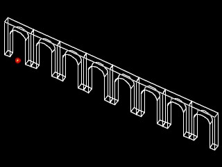
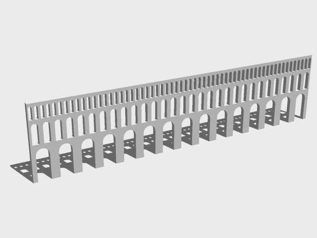
Acquaduct
The acquaduct below consists of a series of arches. Its construction takes the arch of our previous example, copies and transforms it. The script create_acqueduct.gct uses the same graphic functions drawSlab, drawCyl, unionSols and diffSols of the previous example. A new graphics function transSol takes a solid origSol as an argument along with an origin point startPt, a destination point endPt, a specification of the number of copies to make, and a string name that is used to give each copy a unique identity. The arch is copied according to the distance from the startPt to the endPt for the amount of times specified by number. Each successive copy of origSol is translated from previous copy of the origSol according to the distance from startPt to endPt.
Note that for each new solid in the for loop, we concatenate a name with a number by the expression "nameExt = name + "_" + n;" If the input parameter is the string "copySol", then then the first time through the loop, the value of n is equal to 0, and so the name of the first copy is "copySol_0". The second time through the for loop, the value of n is equal to 1, and so the name changes to "CopySol_1", and so on for each addition time through loop.
For each new curTransSol created in the loop, the copy is created with a new construction method "curTransSol.CopyTransformGeometricContents(origSol, startPt, newEndPt);". This constructor creates the new solid curTransSol by copying and tnanslating the original solid origSol according to the distance from startPt to newEndPt. Note that the location of newEndPt is updated each time through the loop, incremented in distance along the x, y, and z axis according to the distance established between the startPt and the original endPt. The function also collects each new solid in a list initialized with the statement "Solid newSols = { };". This array is returned at the end of the function.
| Solid function(Solid origSol, Point startPt, Point endPt, int number, string name){ // transSol // copy and translate a solid Point newEndPt = new Point(); Solid lastTransSol = new Solid(); // create a list of the new arches Solid newSols = {}; //establish translation values double xTrans, yTrans, zTrans; xTrans = endPt.X - startPt.X; yTrans = endPt.Y - startPt.Y; zTrans = endPt.Z - startPt.Z; newEndPt = endPt; string nameExt; for (int n = 0; n < number; n++) { //create distinct name for each translated solid nameExt = name + "_" + n; Solid curTransSol = new Solid(nameExt); curTransSol.CopyTransformGeometricContents(origSol, startPt, newEndPt); newSols[n] = curTransSol; //move target location distance between startPt and endPt newEndPt.ByCartesianCoordinates(baseCS, newEndPt.X + xTrans, newEndPt.Y + yTrans, newEndPt.Z + zTrans); if (n == (number - 1)) { lastTransSol = curTransSol; } } return newSols; } |
We modify the top level function arch to pass along to transSol the arch which we placed in diffSol for copying and transformation. The pimary modification is in the very last part of the function as noted in the text box below. First, a new Point transPt is created to establist the translation distance of each new copy of the arch from the basePt of the first copy. Next, the function transSol is called with parameters corresponding to origSol, startPt, endPt, number, and name as we have just described for the function transSol. The copies of the arch solid are assigned to a new list transSols.
| function(){ // arch (modified) // create a boolean arch, translate and copy it Point basePoint = new Point(); Point topPoint = new Point(); Solid solSlab1 = new Solid(); Solid solSlab2 = new Solid(); Solid solCyl = new Solid(); Solid uSol = new Solid(); Solid diffSol = new Solid(); Solid transSols = {}; //added to previous version of this function double sWidth, sDepth, sHeight; basePoint.ByCartesianCoordinates(baseCS, 0.0, 0.0, 0.0); sWidth = 15.0; sDepth = 5.0; sHeight = 30.0; // Build A Slab solSlab1 = drawSlab(basePoint, sWidth, sDepth, sHeight, "slab_1"); topPoint.ByCartesianCoordinates(baseCS, basePoint.X, basePoint.Y, basePoint.Z + sHeight); // Build A Cylinder on top of the Slab sWidth = 15.0; sHeight = 5.0; solCyl = drawCyl(topPoint, sWidth, sHeight, "cylinder_1"); sWidth = 25.0; sDepth = 5.0; sHeight = 42.5; // Draw the larger slab solSlab2 = drawSlab(basePoint, sWidth, sDepth, sHeight, "slab_2"); // Union the first Slab and the Cylinder uSol = unionSols({solSlab1, solCyl}, "slab_cyl_1"); // Subtract the sold union from the larger slab diffSol = diffSols(solSlab2, uSol, "arch_1"); // LINES ADDED TO PREVIOUS VERSION OF THIS FUNCTION // Create transformation Point Point transformPt = new Point(); transformPt.ByCartesianCoordinates(baseCS,basePoint.X + sWidth, 0.0, 0.0 ); // Copy and transform Solid & return last solid transSols = transSol(diffSol, basePoint, transformPt, 7, "copySol"); } |
This chapter has introduced solid primitives and the the solid modeling operations of UNION, INTERSECTION and SUBTRACTION. We have seen how these solid model operations can be used to reproduce some well know forms in classical architecture, such as the groin vault, the pendentive and the arch. We have also learned about using solid objects as arguements to a function and as return objects from functions. This engages a more sophisticated form of function writing, where we not only do we create new graphics in the drawing database, but where we also further modify the graphics. This technique is one of several possibilities of with working more directly with the drawing database (e.g., intersectSolid.BooleanOperation(solid1, solid2, intersect);). The optional exercise below uses this approach in steps to buid an acqueduct.
Assignment 8: Solid Modeling and Boolean Operations [optional,Spring 2009].