
COMPUTER
AIDED
ARCHITECTURAL DESIGN
Workshop 19 Notes,
Week of December 1, 2025
VRAY SCATTER, PROXY OBJECTS & ANIMATION
This workshop is focused on the use of the VRay Scatter function, and situates a Proxy tree and Proxy grass in so called "areas", a surface that can "host" proxy files as "guests". Since the density of grass proxy instances is higher than that of the tree proxy instances, it relies upon two copies of an elliptical surface "area" to control the number of each of them on the ground separatey.
Part I: Creating the Scatter Areas and Proxy Guests
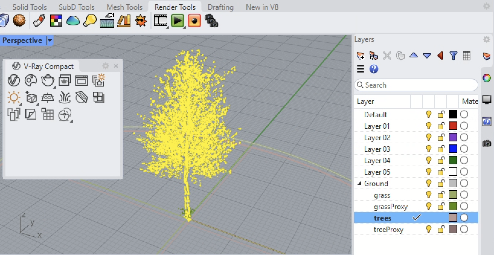
1. Initiate a Rhino drawing file at the scale of large objects in feet. Begin creating an ellipse centered on the origin, with one radial axis from 0,0, to 50,0 and the other radial axis from 0,0 to 35,0. We then fill the ellipse with a planar surface, and copy that surface a nominal distance below the original one. The first surface will host the grass and the second suface will host the trees. In the figure below, the ground layer world XY plane holds the original ellipse, the green grass layer will "host" the grass proxy instances and the brown "tree layer" below it will host the trees proxy instances.
2. Note the copy of the VRay Proxy Library located inthe ARCH 2710 CLASSES Server Collab Folder. To save time and space for the class as a whole, you may reference files in that same location as long as you are logged into the VMWare system or are using one of the School's computer workstations, either the Thin Client workstations in Campbell 105, or the standalone networked workstations in Campbell 107 or Campbell 302. Since this is a shared resource, none of these files may be modified.
Please do not download the entirely library to your personal submit folder on classes as it will vastly increase the disc space for the class as a whole and potentially exceed our quota. However, once you've gained some facility with the Proxy Object system, you may want to discretely copy the single objects and textures to your personal folder project subfolder to reference the items there as illustrated below. Remember that once you are logged off one of the School's computer worktations, you would break the connecton to the Proxy objects. If you download the 30 day trial version of VRay for Rhino on a Windows computer you could potentially create subfolders for the Proxy files you need there for use with Vray.
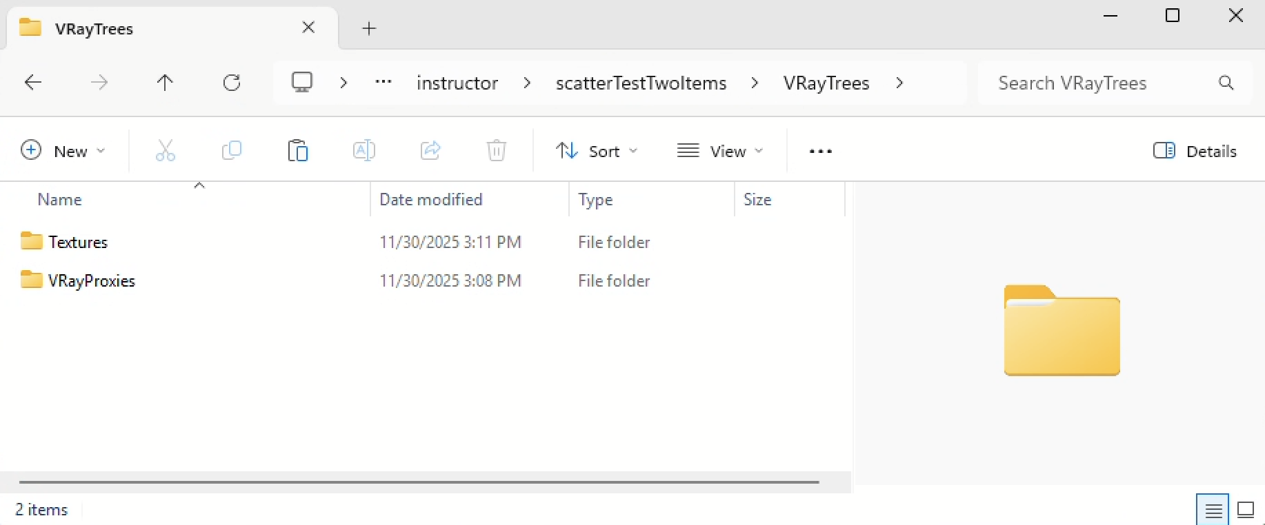
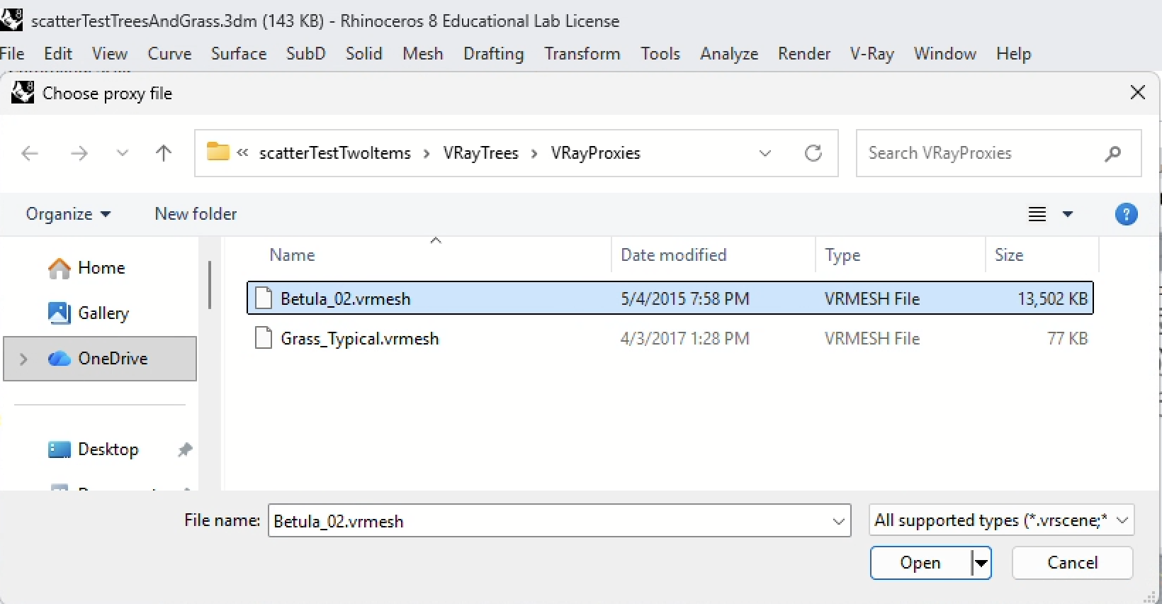
Here is an example of downloading and copying specific .vrmesh (geometry) and texture maps to your personal folder on the CLASSES server or personal computer. Note that this sytem will not be useful without installing VRay on your personal computer. In this case I've created a "VRayTrees" subfolder which in turn has two subfolders, one for "Textures" maps and the other for "VRayProxies" files (You don't need to store the original geometry Rhino "3dm" files that were used to create VRay Proxy Objects.) :
Below is a minimal "VRayTrees" subfolder:
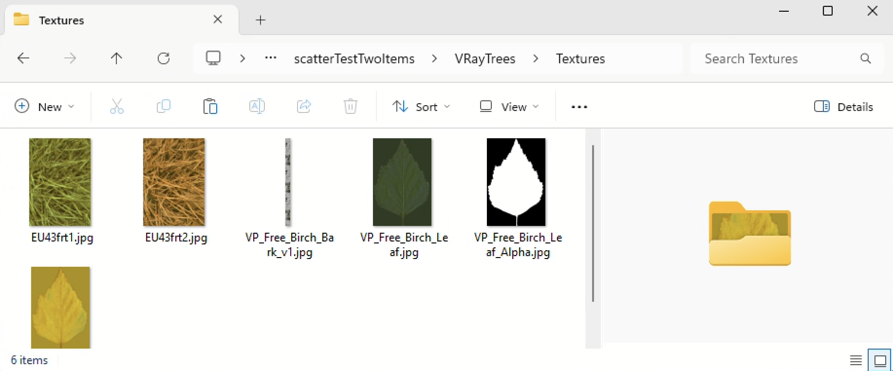
It has a "Textures" subfolder to be applied to the proxy file geometry:
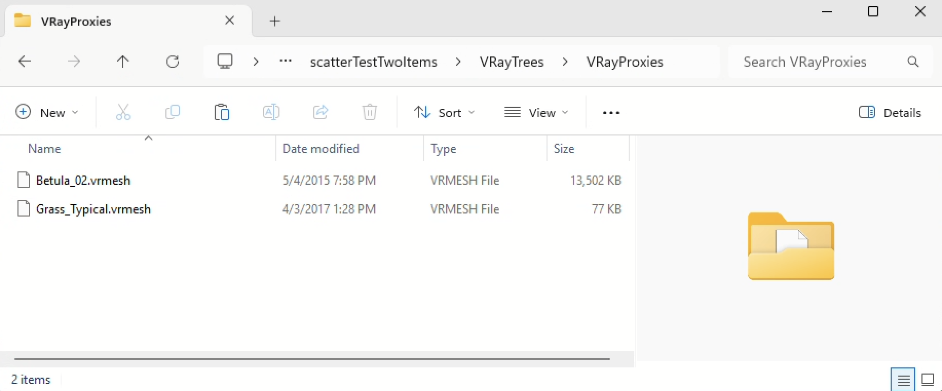
It has "VRay Proxies" subfolder to hold the proxy file "vrmesh" files that contain the geometry:
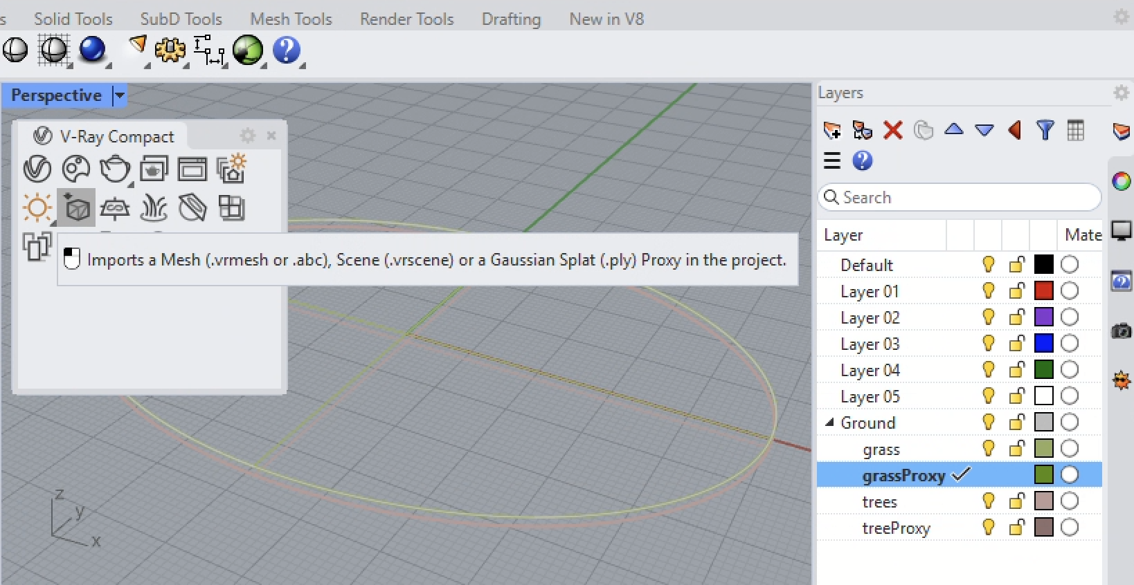
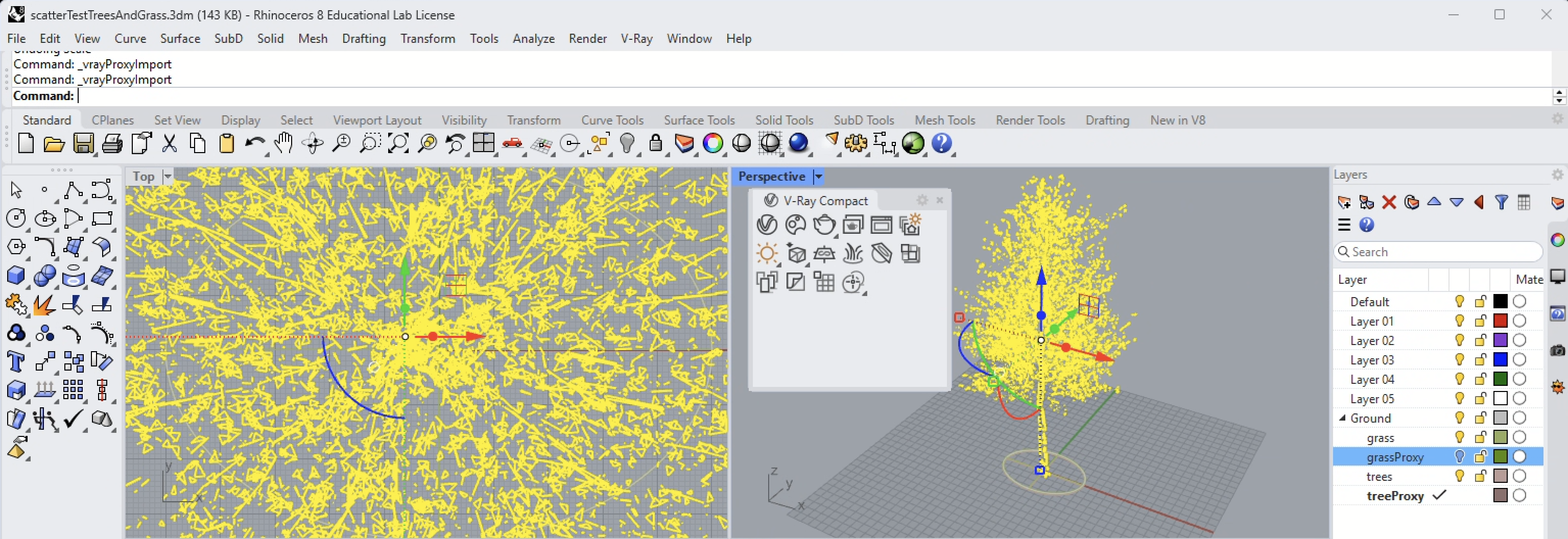
3. Using the VRay Proxy tool, add a VRay Proxy Grass to a new "grassProxy" sublayer, and add VRay Proxy Tree to a new "treesProxy" sublayer, placing both at the origin (0,0,0) of the model space.
Start with the Import VRay Proxy Tool from the VRay Compact Model with the "grassProxy" sublayer active:
Select the Grass Proxy:

Place it at the Origin (0,0) on the VRay Grass Proxy sublevel and then scale it to 0.1 (10 %) relative to the origin:

Similarly, select the VRay Tree Proxy:
Place it at the origin on the treeProxy sublayer:
Scale the tree to 0.1 (10 %) relative to the origin:

You can add additional proxy objects and place them on corresponding layers as needed, but this example just works with two proxy objects.
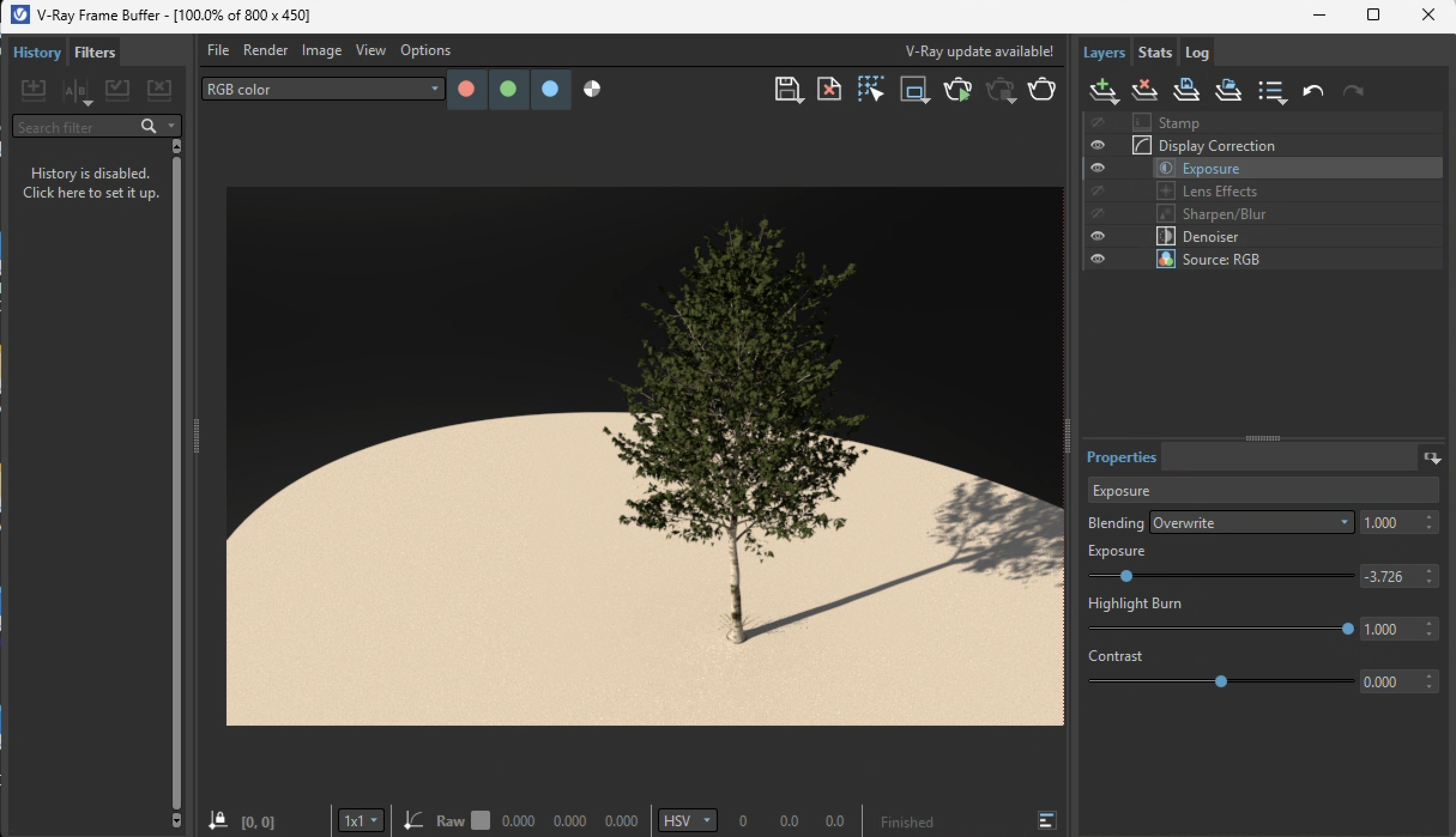
4. As described in Workshop Notes 16, create grass, bark, and leaf VRay materials and assign them to the proxy objects. See Workshop Notes 16 for these details. For this example, we also activate the Rhino Render Sun, similar to Workshop Notes 14, and then test the rendering for both proxy files separately.
Grass:

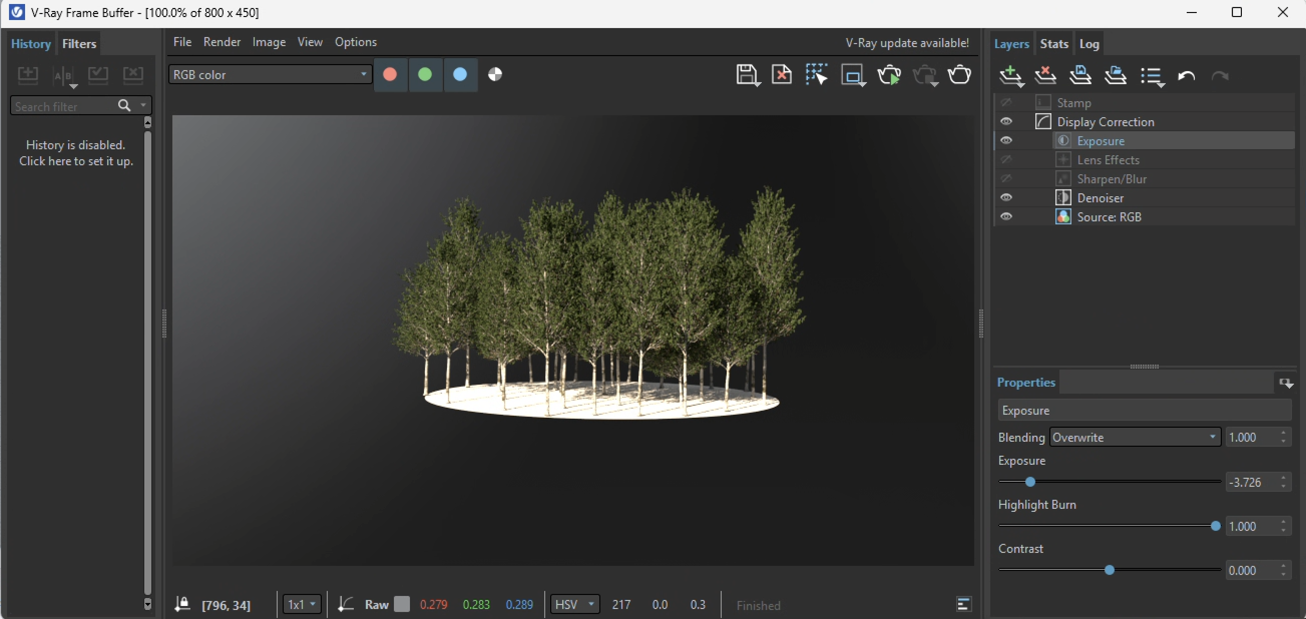
Tree:
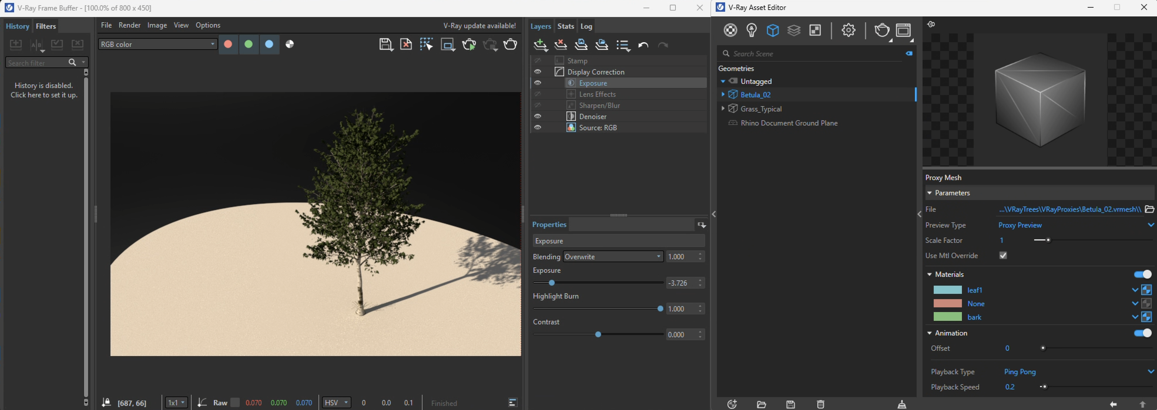
Note: In the VRay Asset Editor some colors may be assigned to the VRay proxy that don't appear in the preview rendering (the red middle color below), whereas the other twocolors (cyan and green) are visible in the preview render and therefore are applicable to the proxy. This means in the case for this tree that the red color can be ignored and no material needs to be assigned to it:
4. Working withthe VRay Compact Menu select the ellipse surface on the Proxy Trees sublayer and select the icon "Select Scatter Host" option:

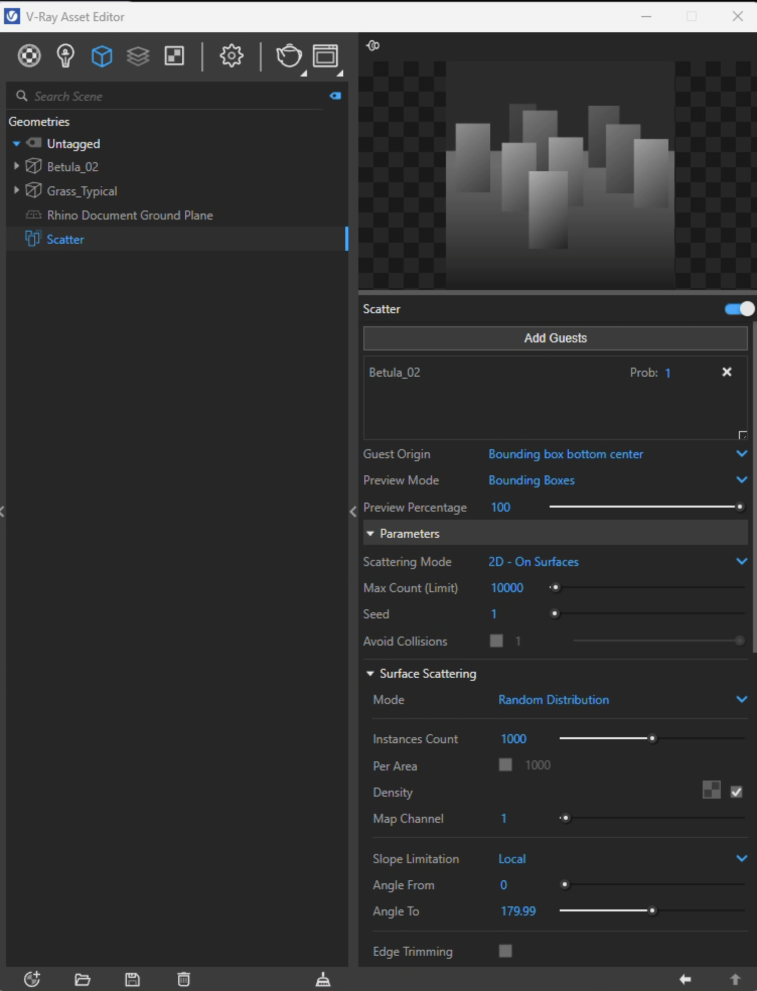
5. Within the VRay Asset Editor, Geometry Tab (blue box icon). select the Scatter Host entity so that it's properties appear on the right-hand side of the Asset Editor window:

6. Select "Add Guests" button on the upper right hand side and select the tree and any other guests (non in this case):
7. At the Rhino Command Prompt, as directed press the "Enter" or "Returnr" key.
8. The VRay Asset Editor now displays the selected element "Betula-02" on the right-hand side of the dialog window.
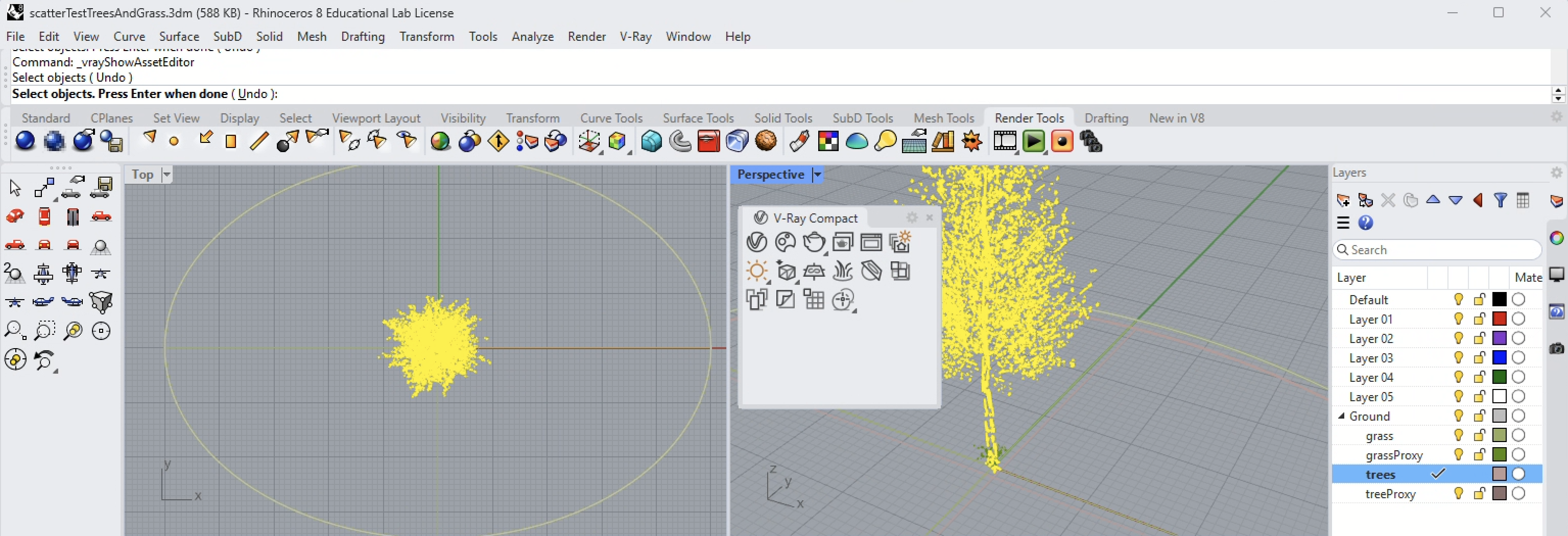
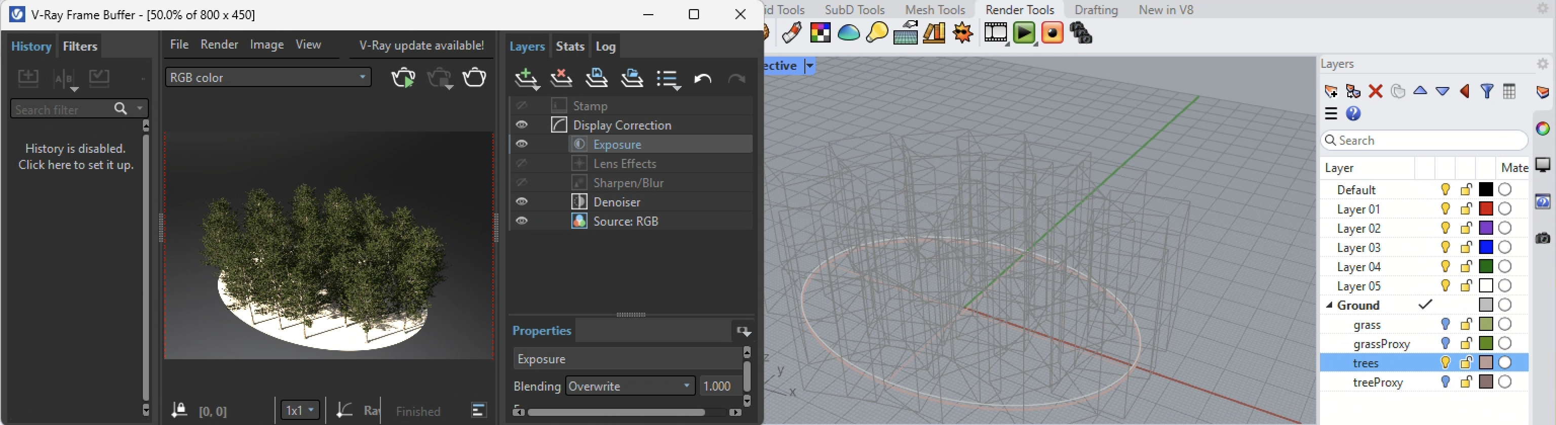
9. However, the density of the gues proxy tree on the surface "area" is so thick that it is difficult literally to see the tree from the forrest of them in the perspective view.

Part II. Controlling Density and Variation
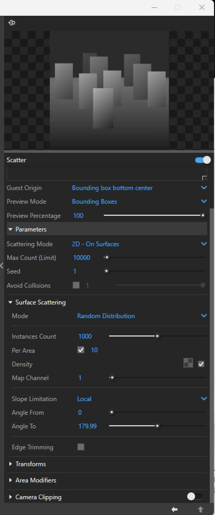
`. Select the check-box "Avoid Collisions" on the right-hand side of the VRay Asset Editor:

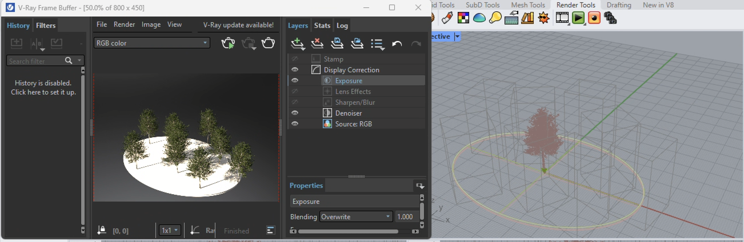
2. The trees immediately thin out to a more clearly well defined number.
3. Now we can do more to adjust the range of scale, rotation and interpenetration of the tree footprints. Here the slider adjacent to "Avoid Collisions is adjusted to 50%, allowing for more interpenetration.

4. Next the layer holding the original Proxy tree is turned off to avoid complicating the distribution of the trees within the new allowable interpenetrated 50% level, and the trees appear more dense as well.
5. The "Transforms" on the right-hand side of the V-Ray Asset Editor dialog box provide a means to vary the height and rotatation of the individua trees.

6. Now, the settings as modified allow the original height to range from 75% to 170% of the uniform height.

7. The image below shows the resulting change in heights of the different trees.

8. Similarly, the rotation settings can be randomized. The settings below have them at a uniform rotation. That is, each tree is still at variable scale, but their rotations are all the same.

9. The result upon rendeirng is what was viewed in the previous image.

10. Now, the rotations are given an incremental randomized step size of 15 degrees (0 to 15 degrees) so that they will be rotated from one to another in a randomized fashion from 0 to 359 degree (360 degrees total).

11. Next, the rendering shows that they are at rotated varied at angles around the vertical Z axis.
12. Similarly, the proxy grass can be set to a new scatter component to avoid collisions.

13. However, by turning off the avoid collisions option, the density per area can be used to control the spacing of the grass instances. In the image below the "Avoid Collisions" check box is turned off and the "Per Area" checkbox is in its default state of being turned off.

14. Howeve, the density per area is used to control the spacing between the proxy grass instances, and is adjusted from the default value of 1000 to 10.
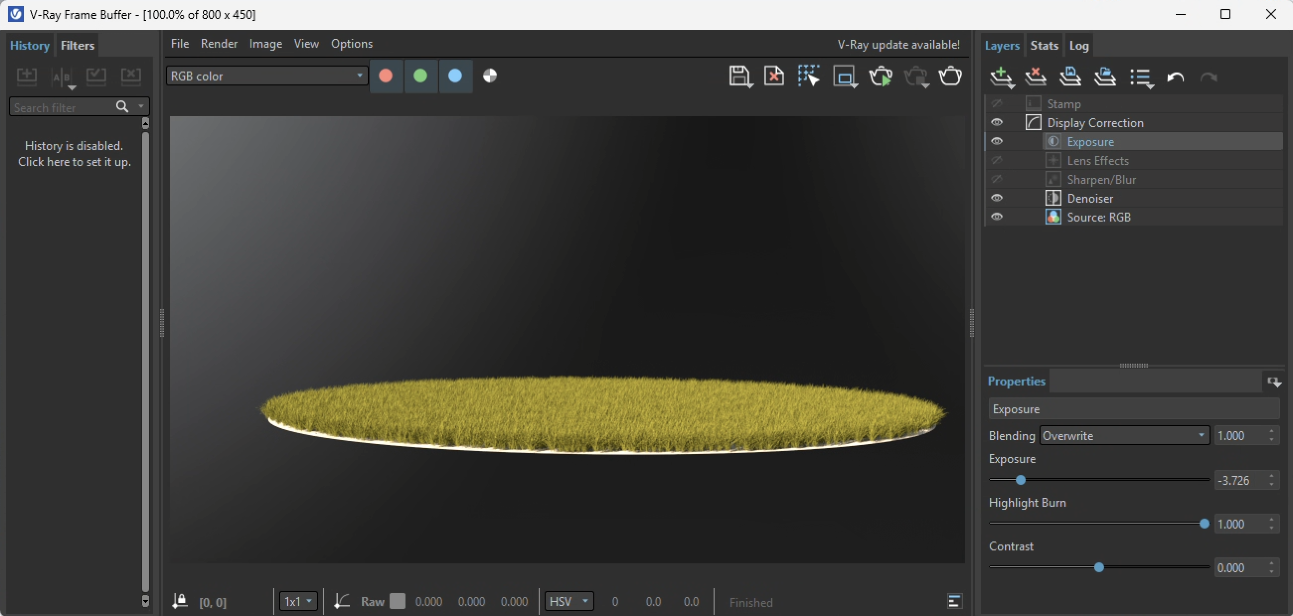
15.The results of this new means of "Per Area" specification is as indicated in the rendering below.
16. Next, similar to randomizing the height of the trees, the height of the grass can also be randomized from 25 % to 200%.

17. The result in the image below appears to be somewhat less uniform in height.

19. Additional modifications to the random height and juxposition of the two scatter components are combined with other elements to yield an expanded height range for randomized grass height in the following test rendering.

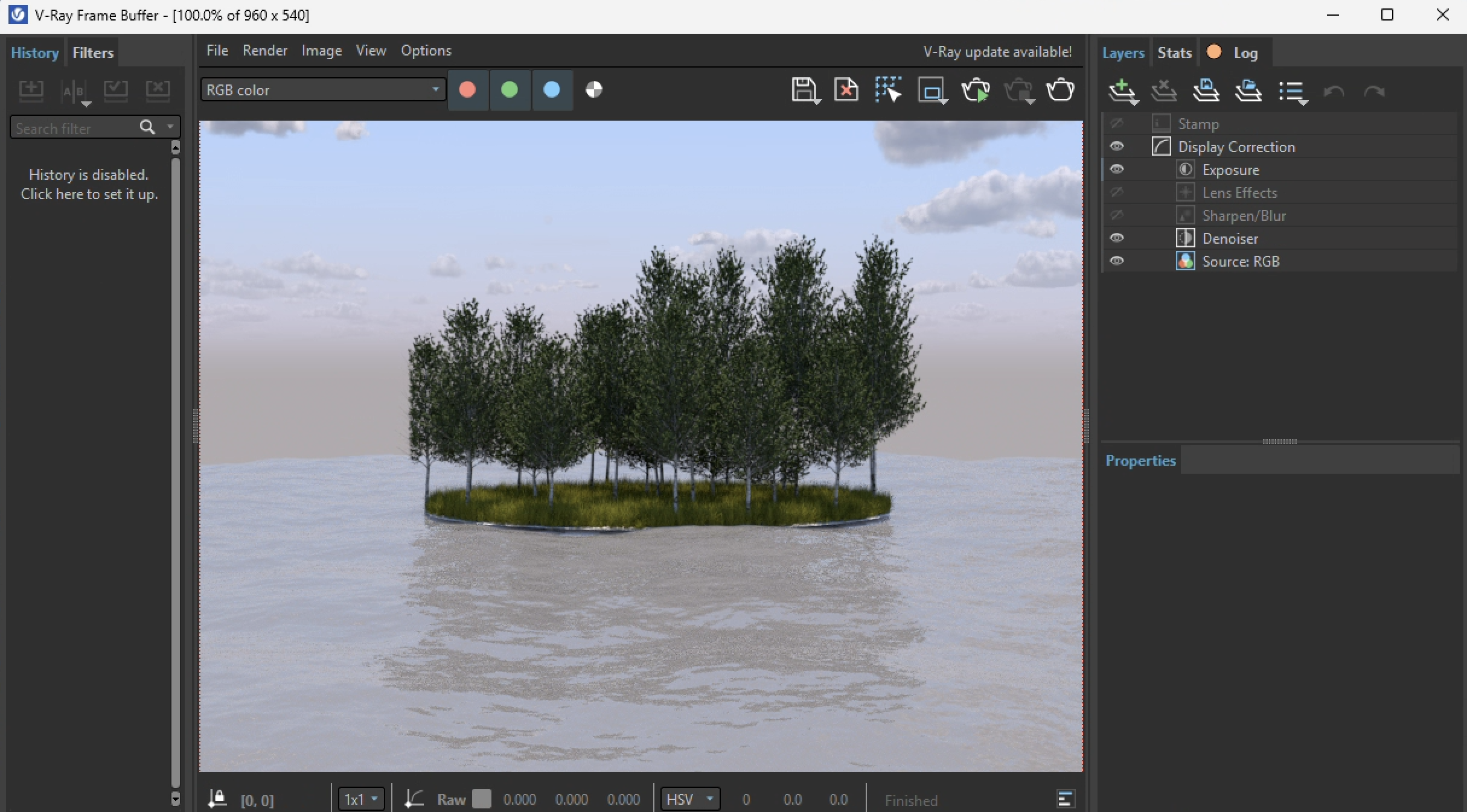
20. This example is extended by adding additional VRay elements. This includes a VRay background sky and a ground surface that is assigned a water material with an animated water material displacment map. They are incorporated ino the Rhino model and test rendered.
21. The same model is then used to generate the following Rhino Sun solar animation using the methods illustrated in previous workshop notes 14.